Design criteria for multi-layered scintillating fibre arrays with inclined columns
Abstract
Multi-layered scintillating fibre arrays read-out are commonly used as high resolution charged particle hodoscopes. Fibres of a “column” along the geometrical trajectory of incident particles are typically grouped to one pixel of a multi-channel read-out device. In some applications the incident particles will cross the detection plane with large angles w.r.t. the normal to the layers. Then, the packing of the fibres needs to be adapted to the incident particles and the columns need to be inclined. In this paper possible fibre array geometries are shown, relevant design criteria for detectors are discussed, and the effect of diverging particles incident on fibre arrays was studied using a Monte Carlo simulation.
keywords:
tracking and position-sensitive detectors, scintillating fibres, particle detector designPACS:
29.40.Gx , 29.40.Mc , 85.60.Ha, , and
1 Introduction
Detectors comprising scintillating fibres, packed together to form arrays, and multi-channel photo-detectors have been used since the 1990s to track charged particles, see e.g. Baer1994 ; Bosi1996 ; Horikawa2004 . A fibre array is made from layers of fibres, often with alternating layers off-set relative to each other. The design of such detectors is governed by the relatively small light yield of thin ( 1 mm) fibres.
Multi-channel photomultiplier tubes are especially suitable for fibre read-out because of the good matching between the pixel size of the photomultiplier and common fibre diameters, offering a significant reduction in size and cabling with respect to conventional tubes. Since the pioneering work of Kuroda Kuroda1981 such tubes have been developed in order to meet the demands on precise and reliable tracking devices under high-rate FAROS1995 ; FAROS1996 ; Agoritsas1998 . In recent years they have been continuously improved. The drawbacks of early devices have been greatly reduced; modern multi-anode tubes exhibit little cross-talk and a high gain uniformity between pixels. The Hamamatsu Photonics R5900 series has been chosen by many experimental groups for fibre read-out.
In modern experiments, fibre bundles involving a rather large number of channels are easily read out via multi-channel photomultiplier tubes, while the use of single-channel photomultiplier tubes is no longer economical in terms of cost and space requirements. Accordingly, multi-layered structures of packed scintillating fibres coupled to multi-anode photomultiplier tubes became the preferred choice for some fast detectors, the fibre trackers in the COMPASS experiment Horikawa1999 at CERN being one recent example.
Fibres of a “column” along the geometrical trajectory of incident particles are typically grouped – with one fibre from each layer — to one common pixel of the multi-channel read-out device. If the light yield per crossing particle is too small to be detected with the required efficiency, layers need to be added to the array. In case charged particles are crossing the fibre array at right angle to the detector base the total thickness of the array can be increased arbitrarily until a physical limit or restrictions in terms of small angle scattering are reached. This condition applies to many applications, as the angular acceptance for fibre hodoscopes is generally small, typically up to 3∘. However, in some applications the incident particles will cross the detection plane with large angles, , w.r.t. the normal to the layers, and would traverse several neighbouring columns. The resultant large hit multiplicities would compromise the tracking capabilities of such a detector. For the fibre hodoscopes of the DIRAC experiment the detector response to particles with incident angles up to 45∘ was studied for background issues Gorin2006 . The read-out electronics of that detector lead to a strong suppression of detection efficiency for larger angles. For restoring the original spatial resolution the packing of the fibres needs to be adapted to the incident particles’ direction and the columns need to be inclined. Only the KaosA1 experiment is known in which the fibre column angle, , w.r.t. the normal to the layers is adapted to large ( 45∘) incident angles of the particles for deliberately matching the geometry Achenbach-SNIC06 ; Achenbach-HYP06 . In the spectrometer’s electron arm hodoscope the average incident angle is 65∘. It has been shown that a high detection efficiency and a good spatial resolution can be achieved using detectors with inclined columns.
2 Fibre array geometries with inclined columns
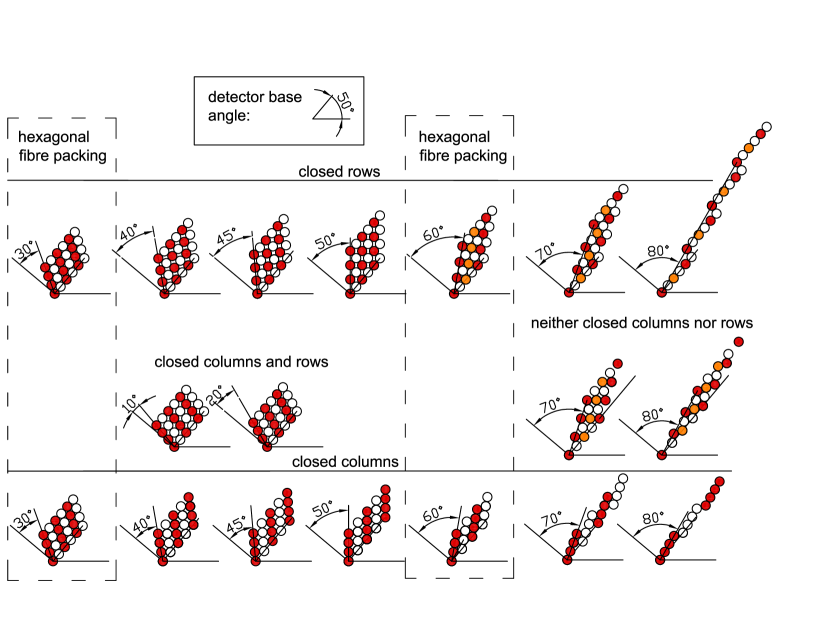
Fibre array geometries with different column angles, , ranging from 10∘ to 80∘ and four fibres per column are shown schematically in Fig. 1. In the scheme the base of each detector is turned by an angle of 50∘ to the horizontal. The most efficient way to pack fibres together to form inclined columns is not obvious. “Rows” of fibres are defined along the layers in the direction of the detector base. For column angles between 30∘ and 60∘ the arrays can be formed in a way that all fibres of a column touch each other (closed columns), but leaving gaps to the corresponding fibres in neighbouring columns. Alternatively, the arrays can be formed with corresponding fibres of neighbouring columns touching (closed rows), leaving gaps between fibres within a column. Finally, for column angles below 30∘ both columns and rows can be closed. For column angles of 30∘ and 60∘ the fibre centres are forming a hexagonal lattice. For a column angle of 45∘ the fibre centres are forming a square lattice. The hexagonal packing, in which each fibre is surrounded by 6 touching fibres, has the highest packing density of 0.90. Square and hexagonal packing geometry are used most often for fibre arrays. Each geometry corresponds to a different overlap fraction, a different column pitch, a different detector width and length for a given number of layers and read-out pixels, and a different average thickness. The relevance of these design criteria for choosing the detector geometry vary with the specific application. Primarily, the fibre array needs to provide a high enough light yield per read-out pixel to discriminate the signals against noise. Light yield and detection efficiency depend on the diameter and overlap fraction as well as on the number of layers. Secondly, the spatial resolution depends on fibre diameter and column pitch. A detector geometry with closed columns as shown in the figure will have a relatively large column pitch and a relatively small spatial overlap. This leads to low spatial resolution and low detection efficiency. Both can be avoided by placing the layers not along the base of the detector, but with a smaller column pitch and larger spatial overlap. That will create a shift between the first fibres of each column and the base-line it was supposed to track. By occasionally (every 3 or more columns) moving the column position one full fibre diameter in the direction of the base-line the shift will be corrected. These geometries have the advantage of being better adapted to practical applications, but have less symmetry. For column angles above 60∘ geometries with neither columns nor rows closed can be created in a similar way. In practice, only those fibre arrays can be built which allow precise mounting and alignment during all stages of the processing: gluing, bending, and installation.
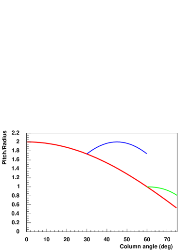
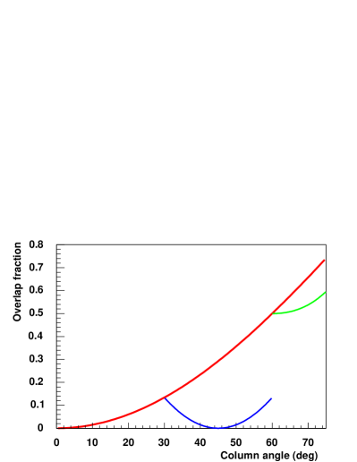
Fig. 2 (left) shows the ratio of the column pitch to the fibre radius, , i.e. the distance between two fibre centres along the base direction in units of fibre radius, as a function of the column angle, . The main branch starting at a ratio 2 corresponds to a geometry with both, closed rows and closed columns, for which . The branch splitting off at corresponds to a geometry with closed columns, where . The continuous curve is calculated for the geometry in which the rows are closed. The branch splitting off at follows a dependence and corresponds to closed columns. Spatial overlap is important to avoid relying on the detection of events with only a grazing contact of the charged particle with the fibres. A particle which crosses the gap between two fibres in one of the layers needs to traverse a significant portion of the full fibre diameter in the other layer. Fig. 2 (right) shows the overlap fraction, , which is the overlap of two neighbouring fibre columns in units of the fibre radius. It is directly related to the pitch to radius ratio by . Fibre diameter and overlap fraction relate to the theoretical spatial resolution of fibre arrays expected from the geometry. For events in which exclusively one column was hit, the the spatial resolution is . For events in which the particle trajectory covered purely the inter-column region, the spatial resolution is given by . Averaging both event types leads to a combined resolution of . For fibre detectors in hexagonal packed arrays the total overlap is with a pitch of . The theoretical spatial resolution of such an array is .
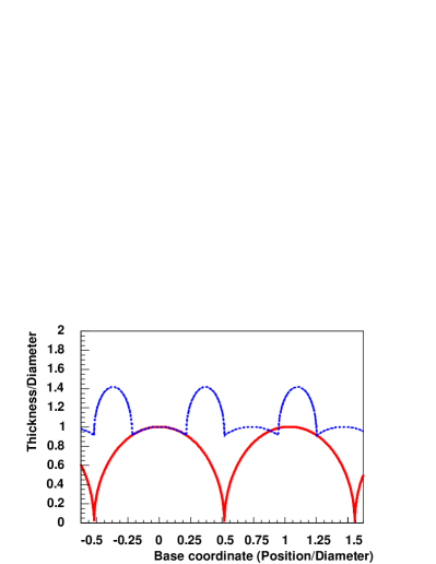
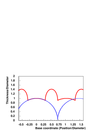
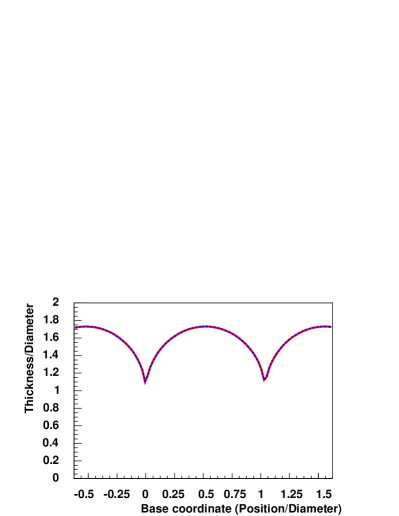
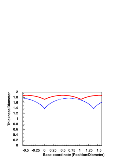
The spread of energy deposition in a fibre bundle is proportional to the detector thickness variation. Fig. 3 shows how the double layer thickness varies as a function of the base coordinate. In the hexagonal packing with a column angle of 60∘ the variation is (minimum to maximum) per double layer. For all other column angles the variation can become smaller, depending on the fibre array geometry.
3 Monte Carlo simulation for diverging particles
The design criteria discussed so far only apply when all particles cross the detector with the same incident angle. The expected response of a detector to diverging particles can be evaluated in a simulation. Different fibre arrays, in which particles were crossing the detector with finite incident angles with respect to the column angle, were included in a detector simulation within the Geant4 framework GEANT4 . Incident electron trajectories were averaged over the base. The simulation gave information on the energy deposition in individual fibres and on interactions of the particles with the material, e.g. small angle scattering, ionisation and bremsstrahlung. The total energy deposited in the active cores of the four corresponding fibres of each column was calculated. Signals above a given threshold were assigned to the corresponding read-out pixel.
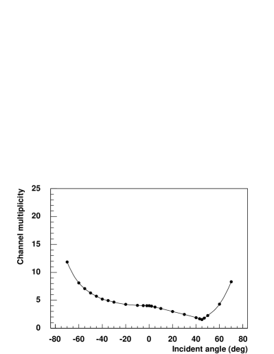
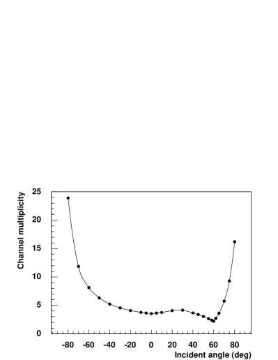
The increase in channel multiplicity for detectors with column angles of and is presented in Fig. 4 as a function of the incident angle . It is shown that the multiplicity increases gradually to smaller incident angles but steeper to higher angles. Owing to the symmetry of the fibre arrays, a local maximum of the multiplicity appears for at 30∘, and for at 0∘. It is obvious that the columns must be aligned with the incident particle direction and the particle’s divergence must be small to achieve a minimal multiplicity and an optimal spatial resolution.
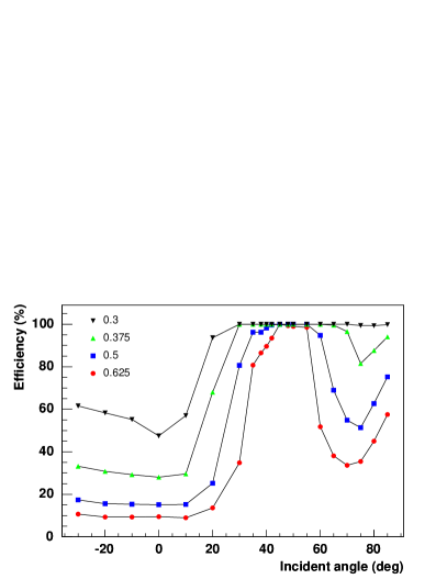
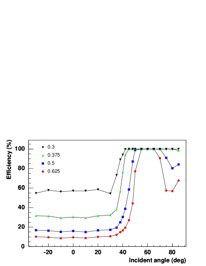
The simulation can further help to define the optimum threshold so that a detector becomes insensitive to incoming particles with large angles w.r.t the nominal angle. That is important when a detector is exposed to a large number of background particles. The angular dependence of the detector efficiency is plotted in Fig. 5 for 4 different relative thresholds. The relative threshold of 100 % corresponds to the mean signal of a detector pixel for events with particles hitting the detector with nominal angle. The plateau width for 100 % efficiency depends crucially on the threshold. For incident angles much smaller than the nominal angle only one fibre of each column is hit, but many neighbouring channels. Thus, the probability for having a signal in at least one pixel above threshold is strongly dependent on the distribution of energy deposition and the value of the threshold, but almost independent on geometry and incident angle.
4 Summary
When a set of fibres from a multi-layered fibre detector is coupled to a multi-channel read-out device a multitude of different fibre array geometries is possible. It is the experimenter’s choice to select the geometry, which is matching the application best, according to the relevant design criteria. In this paper the dependence of column pitch and overlap ratio on the fibre array column angle is discussed. Both criteria are also reflected by the thickness variation of a double layer, which is shown for a selection of column angles. The effect of diverging particles incident on fibre arrays with inclined columns was studied with the help of a Monte Carlo simulation. The resulting curves of channel multiplicity versus incident angle can be folded with the incident angle distribution of an experiment to get the average channel multiplicity. Large multiplicities compromise the position resolution of the fibre arrays, which is the key issue for tracking detectors. With the choice of the detection threshold, the sensitivity of the detector to particles with large deviations to the nominal angle can be varied.
Acknowledgements
This work was supported by the Federal State of Rhineland-Palatinate and by the Deutsche Forschungsgemeinschaft with the Collaborative Research Center 443.
References
- [1] J. Bähr, et al., Nucl. Instr. and Meth. A348 (1994) 713–718.
- [2] F. Bosi, et al., Nucl. Instr. and Meth. A374 (1996) 48–56.
- [3] S. Horikawa, et al., Nucl. Instr. and Meth. A516 (2004) 34–49.
- [4] K. Kuroda, D. Sillou, and F. Takeutchi, Rev. Sci. Instr. 52 (1981) 337–346.
- [5] FAROS Collaboration, Nucl. Instr. and Meth. A357 (1995) 78–86.
- [6] FAROS Collaboration, Nucl. Instr. and Meth. A372 (1996) 63–69.
- [7] V. Agoritsas, et al., Nucl. Instr. and Meth. A406 (1998) 393–402.
- [8] S. Horikawa, et al., Nucl. Instr. and Meth. A431 (1999) 177–184.
- [9] P. Achenbach, et al., New detectors for the kaon and hypernuclear experiments with KAOS at MAMI and with PANDA at GSI, in: V. Luth (Ed.), Proc. of the IX. Intern. Symposium on Detectors for Particle, Astroparticle and Synchrotron Radiation Experiments, SLAC, 3–6 April 2006, eConf C0604032, 2006, p. 144.
- [10] P. Achenbach, Probing hypernuclei at anda and at MAMI-C, in: J. Pochodzalla, Th. Walcher (Eds.), Proc. of the IX. Intern. Conf. on Hypernuclear and Strange Particle Physics, Joh. Gutenberg-Univ., Mainz, 10–14 Oct. 2006, Springer, 2007, pp. 79–84.
- [11] A. Gorin, et al., Nucl. Instr. and Meth. A566 (2006) 500–515.
- [12] GEANT4 Collaboration, Nucl. Instr. and Meth. A506 (2003) 250–303.