, url]http://www.iitk.ac.in/cmlds/groupleader.html
Magnetization depinning transition, anisotropic magnetoresistance and inplane anisotropy in two polytypes of La2/3Sr1/3MnO3 epitaxial films.
Abstract
The isothermal magnetoresistance [R()] of [001] and [110] epitaxial films of La2/3Sr1/3MnO3 measured as a function of the angle between current () and magnetic field (), both in the plane of the film, is measured at several temperatures between 10 and 300K. The magnetic easy axis of these polytypes is intimately related to the orientation of Mn - O - Mn bonds with respect to the crystallographic axis on the plane of the substrate and energy equivalence of some of these axes. The magnetization vector () of the [001] and [110] type films is pinned along the [110] and [001] directions respectively at low fields. A magnetization orientation phase transition (MRPT) which manifests itself as a discontinuity and hysteresis in where is the angle between and the easy axis for the below a critical value has been established. The boundary of the pinned and depinned phase on the H-T plane has been established. The highly robust pinning of magnetization seen in [110] films is related to their uniquely defined easy axis. The isothermal resistance R⊥ and R∥ for and , respectively for both polytypes follows the inequality R R∥ for all ranges of fields () and temperatures (10K - 300K). A full fledged analysis of the rotational magnetoresistance is carried out in the framework of Döring theory for MR in single crystal samples. Strong deviations from the predicted angular dependence are seen in the irreversible regime of magnetization.
keywords:
Magnetic anisotropy, LSMO, magnetic thin films, AMRPACS:
72.15.Gd, 73.43.Qt, 75.30.Gw, 75.47.-m, 75.70.Ak1 Introduction
A galvanomagnetic property of fundamental interest in thin manganite films is their isothermal magnetoresistance(MR) measured as a function of the angle() between current and applied magnetic field , both in the plane of the film. This angle-dependent resistivity() in polycrystalline films of metallic ferromagnets follows a dependence of the type[1, 2, 3, 4];
| (1) |
where and are the resistivities for and respectively. The resistivity , often called the rotational magnetoresistance (RMR), derives contribution from two carrier scattering processes one of which depends crucially on the spin - orbit interaction; a magnetization() direction and strength dependent source of anisotropic scattering. While may not be necessarily collinear with due to non-zero magnetocrystalline anisotropy, a grain averaging of in a polycrystalline film yields equation 1. This contribution to RMR, which has been known as anisotropic magnetoresistance (AMR), saturates once the field intensity H exceeds the saturation value Hs beyond which the film becomes a single domain magnetic entity. Another contribution to RMR comes from the trapping of mobile carriers in cyclotron orbits due to the Lorentz force. This localizing effect (a positive contribution to MR), which increases with the carrier mean free path is called the orbital magnetoresistance (OMR). The magnitude of OMR varies as square of the magnetic induction , and shows a constant positive slope for . While the is always greater than for OMR, the relative magnitude of these resistivities can be greater or less then unity for AMR. The sign of the inequality between and is intimately linked with the electronic band structure of the material under consideration. In most of the - transition metal alloys and the magnetoresistance can be as large as in some dilute Ni alloys[1, 2, 3, 4]. In low carrier density ferromagnets such as the hole doped manganites[5, 6, 7, 8, 9], GaMnAs[10] and GdN[11] the anisotropic magnetoresistance is small and negative.
The angular dependence of resistivity as expressed by equation 1, does not hold in the case of single crystal samples with a non-zero magnetocrystalline anisotropy. Here the magnetization is not necessarily collinear with because its direction is decided by the competition between the torques exerted on it by and the crystalline anisotropy field. The dependence of at low fields, in particular when the torque on is not strong enough to depin it from the easy axis, may deviate markedly from the behavior predicted by equation 1. Often, the vs curve has sharp jumps and hysteresis suggesting a first order transition. Such magnetization reorientation phase transition (MRPT) has been seen prominently in Fe film grown on GaAs[12, 13].
It is evident that measurements and analysis of the galvanomagnetic property RMR as a function of field strength and temperature provide rich insight into spin-orbit interaction, carrier mobilities, scattering length and the torques experienced by from the applied field , and various forms of magnetic anisotropies which pin along a certain crystallographic direction. Extensive literature exists on the phenomena of AMR, RMR and OMR on polycrystalline samples of ferromagnets like Fe, Ni and their alloys[1, 2, 3, 4]. There are also a large number of studies on epitaxial thin film of iron in which the deviations from a dependence have been addressed in terms of magnetocrystalline anisotropy[12, 13, 14].
Extension of the ideas used to understand RMR in elemental ferromagnets to complex ferromagnetic oxides of poorly understood magnetocrystalline anisotropy, nature of charge carriers, their scattering mechanism and their coupling to lattice and spin degrees of freedom poses major challenges. One family of complex metallic oxides which has drawn considerable interest in recent years is of manganites of the type A1-xBxMnO3 where A is a rare earth and B an alkaline earth ion. Electrical conduction in these systems is primarily through -electrons hopping between neighboring manganese sites[15, 16, 17]. Understanding the mechanism of RMR in these systems is of fundamental importance.
Most of the studies reported till date on anisotropy of magnetoresistance in manganites have been carried out on epitaxial films of the average bandwidth compound La1-xCaxMnO3 (LCMO, x0.3) deposited on [100] cut SrTiO3 . These ferromagnetic films have in-plane magnetization with [001] as the magnetic easy axis and the magnetic ordering temperature of 270 K. For example, measurements of O’Donnell et al[5] show a striking anisotropy and hysteresis in the low-field MR for and configurations, which they attribute to magnetocrystalline anisotropy and colossal magentoresistance. Ziese and Sena[6], and Ziese[7] have also measured the low-field resistance anisotropy for and configurations in LCMO films at several temperatures. While the sign and magnitude of their AMR are consistent with the phenomenological scattering model of Malozemoff[4], its temperature dependence needs interpretation. Infante et al[8] have measured the isothermal MR as a function of the angle between and at 180 K in [110] oriented LCMO epitaxial films. They attribute the hysteretic angular dependence of MR seen at low field to in-plane uniaxial anisotropy of these films. Hong and coworkers[9] have investigated the effect of injected charges, using a field effect geometry, on AMR of [100] oriented epitaxial La0.7Sr0.3MnO3 films in order to separate the contributions of carrier concentration and disorder caused by chemical doping to AMR. While these and other[18, 19] studies provide a wealth of information on resistance anisotropy in colossal magnetoresistance manganites, the issues which have remained unaddressed are;
-
1.
Although it is evident from low field measurements of O’Donnell et al.[5] on [100] LCMO and Infante and coworkers[8] on [110] LSMO films that there is indeed a non-zero in-plane anisotropy which pins the magnetization vector along the easy axis, the H-T phase space of the pinned phase is not established in these studies. Moreover, the relative strength of the in-plane anisotropy, which is directed along different crystallographic axes for the [100] and [110] films, is not known. There is also a need to understand the fundamental processes responsible for the anisotropy.
-
2.
At larger fields, the magnetization rotates freely with the field. A systematic temperature dependence of which would allow calculation of is, however, lacking. A comparative study of and its temperature dependence in [100] and [110] films would help in separating the band structure related contribution and the role of extrinsic effects such as disorder to anisotropic magnetoresistance.
-
3.
While polycrystalline films of ferromagnets show a simple dependence of isothermal MR, in single crystals this is generally not true. Here the orientation of both current and magnetization with respect to crystal axis is important. In the case of manganites a full fledged analysis of in terms of Döring’s equations[20] is lacking. Such a study is desired to establish significant deviations from the dependence of and the contributions of other scattering processes to RMR.
Here we present a rigorous study of RMR in two variants of high quality epitaxial films of La2/3Sr1/3MnO3 one with [001] and other with [110] axis normal to the plane of the substrate. We have analysed the data in the light of Döring’s equations [20]. The field and temperature dependence of the phenomenological coefficients between a selected range of temperature has also been reported for both types of film. We have also drawn the H-T phase diagram for both films to show the pinned and depinned regions in the H-T phase space. The phase diagram clearly shows that in case of [110] film the pinning of the magnetization vector is stronger than that of [001] film.
2 Experiments
Thin epitaxial films of La2/3Sr1/3MnO3 were deposited on [110] and [001] oriented SrTiO3 (STO) substrates using a multitarget pulsed excimer laser [KrF, = 248 nm] ablation technique. The deposition temperature (Td), oxygen partial pressure p, laser energy density (Ed) and growth rate (Gr) used for the growth of 150 nm thick layers were, 7500 C, 0.4 mbar, 2J/cm2 and 1.3Å/sec respectively. Further details of film deposition are given elsewhere[21]. The epitaxial growth in two sets of films with [110] and [001] directions normal to the plane of the film was established with X-ray diffraction measurements performed in the geometry. We have also examined the surface topography of these epitaxial films using high resolution scanning electron microscopy (SEM) and atomic force microscopy (AFM) techniques. The measurements revealed prominent grainyness at nanometer length scale. In the case of [001] films, the grains were circular of average diameter nm, while for the [110] films rectangular grains of area 70nm X 40nm were seen. However, the long edge of the rectangles did not have a preferred orientation. These isotropic features of the surface texture suggest that the microstructure of these films cannot contribute to in-plane magnetic anisotropy. For transport measurements, films were patterned in the form of a bridge with photolithography and wet etching such that the long axis of the bridge was parallel to [001] and [100] direction for the [110] and [001] oriented films respectively. The measurements of resistivity as a function of temperature, magnetic field strength and the angle between the field and current were performed using a 4.2K close cycle He - refrigerator with a fully automated home made setup for applying the field at varying angles between 0 and 2 with respect to the direction of current[22]. The sample was mounted in a way to keep the field in the plane of the sample for all values of the angle between and . Isothermal magnetization loops (M-H) were measured for both the samples using a commercial magnetometer (Quantum Design MPMS XL5 SQUID) by applying the field at various angles in the plane of the film.
3 Results and Discussions
3.1 Magnetization reorientation phase transition in [110] and [001] films
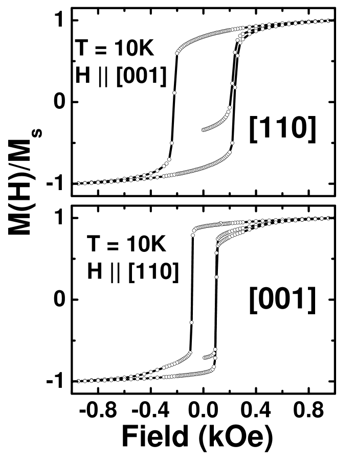
Figure 1 shows the magnetization vs field (M-H) loops for the [110] and [001] epitaxial samples at 10K in terms of the normalized magnetization M(H)/Ms, where Ms is the saturation magnetization. The absolute value of Ms at 10K for [110] and [100] film is approximately 475 and 400 emu/cm3 respectively. These numbers have error due to uncertainty in the measurement of film area and thickness. The magnetic field in these measurements was applied along the easy axis which is collinear with the [001] and [110] crystallographic axis for the [110] and [001] epitaxial films respectively[23]. The coercive fields for the [110] and [001] samples deduced from these measurements are 230 Oe and 90 Oe respectively. The marginally higher Hc of the [110] film seen here appears to be a common feature of such films[24].
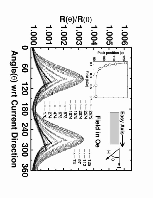
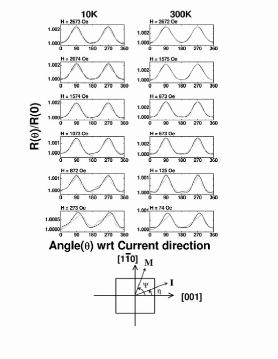
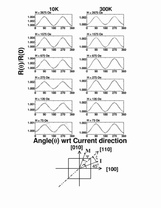
The RMR of a [110] oriented LSMO film at 300 and 10K is shown in figure 2 and figure 3 respectively, where we have plotted the angle () between the directions of current and applied field along the x-axis and the resistance ratio R()/R(0) along the y-axis.
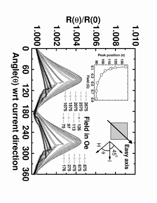
The relevant vectors in the plane of the film are also shown in the right hand inset of the figures. For the measurements performed at 300K (figure 2), we observe a symmetric R()/R(0) curve about and with a periodicity of when the external field H is 300 Oe. Below 300 Oe however, there is a distinct deviation from this symmetry; the peak in resistance is now shifted to . The variation of the peak position as a function of field is plotted in the left inset of the figure. One noticeable feature of the low field ( 300 Oe) data is a sudden drop in resistance once the peak value is reached. This suggests some kind of a depinning transition. For the R()/R(0) vs curves at 10K (figure 3) this deviation from the symmetric dependence persist upto 1100 Oe. Here we also note that at fields below 200 Oe, the resistance has a negligible dependence on the angle between and . One more noteworthy feature of these data is the value of resistance for and configuration. Unlike the case of 3 transition metal films, here . This is an interesting feature of the RMR in manganite thin films[5, 6, 7, 8, 9].
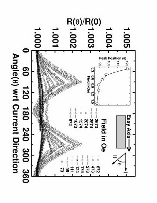
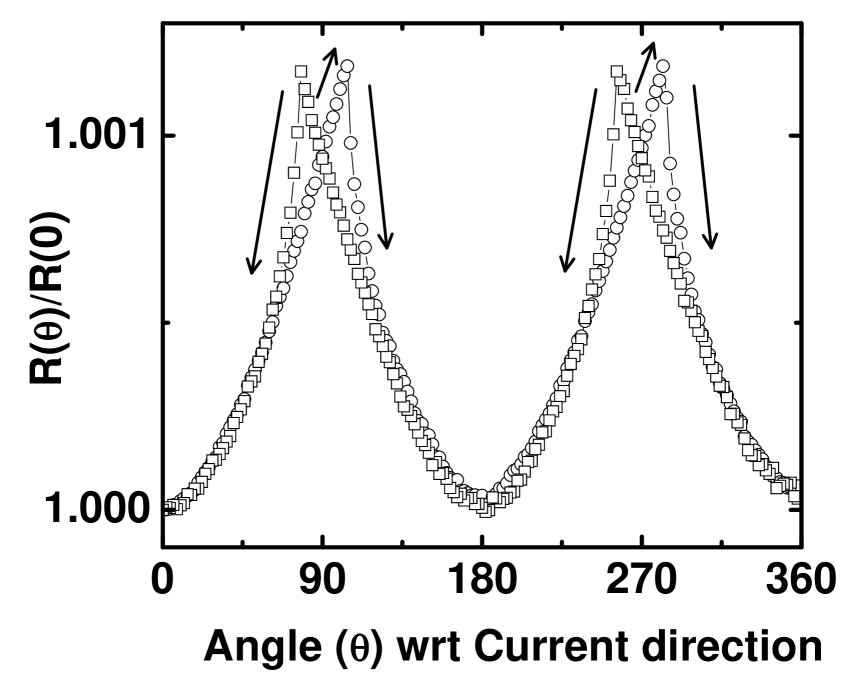
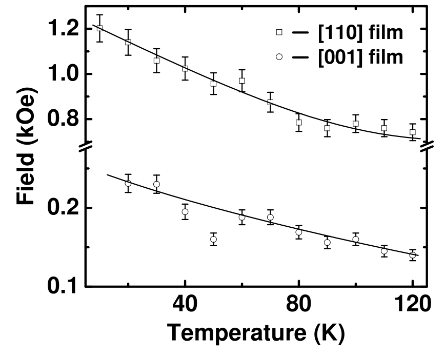
In figures 4 and 5 we have shown the RMR of the [001] oriented LSMO film at 300 and 10K respectively. For the measurements at 300K (figure 4) we observe a symmetric angular dependence of the normalized resistance for all values of the applied field, even at fields as low as 75 Oe. At 10K however(figure 5), the deviates from the symmetric behavior when the field is reduced below 500 Oe. A sharp drop in resistance when the angle is increased beyond for these low field measurements is a remarkable feature of these data. This abrupt drop in resistivity is accompanied by a hysteresis in the vs plots when the angle is traced back from to 0. A typical hysteresis is shown in figure 6. The area under the hysteresis loop decreases with the field. In the left inset of Figs. 2, 3, 4 and 5 we have plotted the as a function of magnetic field strength. As noted from these insets, the peak in RMR deviates rapidly from as the magnetic field is lowered below a critical value H*. We have tracked the variation of H* with temperature between 10 and 120K for the two types of films by measuring at several fields while the temperature is held constant. The result of such a measurements is shown in figure 7.
The discontinuous change in below a characteristic field H* and accompanying hysteresis indicate the existence of a magnetization reorientation phase transition (MRPT)[12, 13, 25] in the system driven by the torque of field on . While a rigorous analysis of the MRPT carried out by minimizing the magnetization free energy functional allows the calculation of the in-plane magnetocrystalline anisotropies, here we simply argue that the line in figure 7 separates the H-T phase space where the magnetization is pinned along the easy axis and where it is free to rotate with the field. It is clear from figure 7 that the magnetization in [110] oriented film remains pinned along the easy axis over much larger H-T phase space campared to the [001] oriented film.
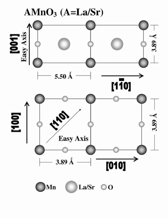
The issue of why the magnetic easy axis in [001] and [110] films of manganites is different with a different degree of anisotropy energy as suggested by the phase diagram of figure 7 has not been addressed in detail although several workers have reported a difference in in-plane anisotropy axis of [001] and [110] LSMO films[24, 26, 27]. It is generally agreed that while for the [001] films the easy axis of magnetization is along [110] direction, the [110] films have uniaxial anisotropy with easy and hard directions along [001] and respectively. In some earlier studies the magnetic anisotropy in thin LSMO films has been attributed to epitaxial strain[24, 26]. Berndt etal.[24] have shown that for [001] films the anisotropy is dependent on magnetocrystalline effect while for [110] film it is determined by magnetoelastic effect. Similarly, Tsui etal.[26] have concluded that the anisotropy of LSMO films is sensitive to symmetry and morphology of substrate but lattice strains can induce an additional anisotropy along the direction of tensile strain. Our group has recently reported[28] dramatic effects of epitaxial strain in magnetic and transport properties of La1-xSrxMnO3 (x=0.55) epitaxial film. However, the effects diminish and bulk-like behavior is seen once the film thickness exceeds nm. Since in present case the films are 150nm thick, it is safe to assume that the strain induced by lattice mismatch between film and substrate is completely relaxed. Lattice parameter of the films inferred from x-ray diffraction measurement support the conclusion(Å, Å and Å). Since the topography shows circular and randomly oriented rectangular grains and x-ray diffraction yields a bulk-like lattice parameter, it can be concluded safely that the magnetic anisotropy of [001] and [110] films is not an artifact of strain. However, we expect a fundamental contribution of the orientation of Mn-O-Mn bonds to magnetic anisotropy. In figure 8 we sketch the atomic arrangement on the top layer of the [001] and [110] cut SrTiO3 crystals and the way epitaxial registry is maintained when La2/3Sr1/3MnO3 film grows on the top. We can see that in the case of [001] oriented film the Mn - O - Mn bonds are directed along the [100] and [010] direction making them energetically degenerate. To avoid this degeneracy the magnetization vectors prefer to lie along the [110] direction making it the easy axis. The difference in the energy of the [110] and [100]/[010] states of magnetization is expected to be small. This is perhaps the reason why the depinning field in this case is substantially lower. In the case of the [110] oriented films, the Mn - O - Mn bond, with a length of 3.89Å, is directed along the [001] direction, whereas along the direction the two Mn ions are separated by 5.5Å without any bridging oxygen. This makes the [001] direction the preferred direction for orientation of the magnetization vector. Furthermore, as the [001] and directions are highly inequivalent, the pinning of along [001] is expected to be robust, which is really the case seen in the phase diagram of figure 7.
3.2 Temperature dependence of RMR
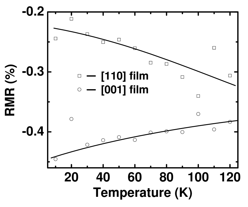
In figure 9 we plot the percentage RMR defined as at 10 and 300K for the two types of films as a function of field. The RMR is negative in both the cases. For the [001] film at 300K, it is also nearly constant at all fields. For the same film at 10K the magnitude of RMR first increases rapidly with field and then acquires a saturation value of at H 1 kOe. For the [110] film the RMR at 300K saturates to at H kOe. The same film has the RMR of at 10K. It is somewhat surprising to note that the RMR of the [110] film decreases while for [001] it increases as we go down in temperature.
In order to address this issue further, we have measured the 2500 Oe RMR of these films at several temperatures between 10 and 120K. These data are shown in figure 10. We note that the RMR of both the samples is negative and its amplitude in the [001] case decreases monotonically as the temperature is raised to 120K. In fact the RMR deduced from and measured between 120 and 240K shows that this drop continues till 240K. For the [110] sample however, the magnitude of RMR first increases with temperature till T 200K and then drops on increasing the temperature further.
In the one band model of Malozemoff[29] as applied to manganites by Ziese and Sena[6, 7], the AMR is given as;
| (2) |
where is the spin - orbit coupling constant, the crystal field splitting and the exchange field. By putting in the value of , and for a typical double exchange manganite they find that in the limit of zero temperature. While a precise temperature dependence of the parameters and is not known, in manganites of K a significant enhancement in AMR near the Curie temperature (Tc) has been observed. Herranz etal.[30, 31] have argued that as the Curie temperature is approached, the double exchange mechanism is impeded by the enhanced Jahn-Teller distortion of Mn-O octahedron with concomitant unquenching of the orbital angular momentum which enhances the spin-orbit interaction and hence the AMR. Our data, however, suggest that in these high quality films of La2/3Sr1/3MnO3 where Tc is 360K, the AMR decreases on warming to 300K. While we have not been able to measure the AMR at T 300K due to experimental limitations, this is an important issue that needs to be addressed in future.
A rigorous analysis of the RMR data of our samples needs to be done using the approach of Döring[20] which entails writing the magnetoresistance of a cubic ferromagnet as a series in magnetization and current direction cosines and respectively as [20],
| (3) | |||||
where is the resistivity at T = 0, ’s are phenomenological constants, is a numerical constant depending on the easy axis direction, and . For the situation when magnetic domains are distributed equally among the easy axes in zero applied field. The constant c is 1/4 for [110] easy axis and zero for [100] easy axis[7]. For the purpose of our [110] films, the analysis is similar to that used by Gorkom etal [14] for [110] Fe with [001] easy axis. Following this work, we can write , , and , where is the angle between the magnetization and the [001] axis and , the angle between the electrical current and the [001] direction. A sketch of three vectors , and the unit vector pointing along the easy axis in a most generalized situation is given at the bottom of figure 11. On substituting these parameters in equation 3 one gets,
| (4) | |||||
| where, | |||||
| (5) | |||||
| (6) | |||||
| (7) | |||||
| (8) | |||||
| (9) |
In our case hence . This result leads to . Since depends only on and which in turn are temperature dependent coefficients, we can lump in for an isothermal measurement, and then, the right hand side of equation 4 can be written as , where is the resistance at the peak position.
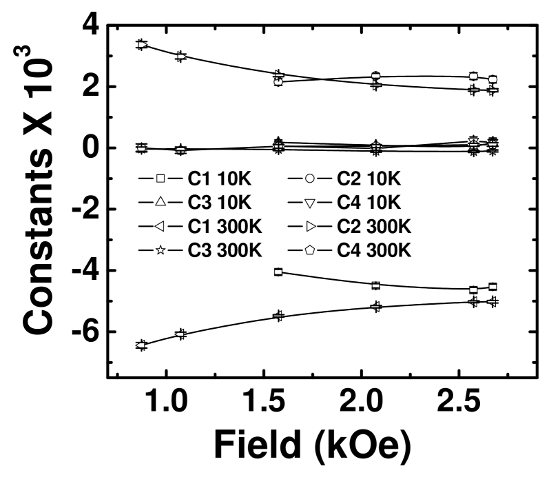
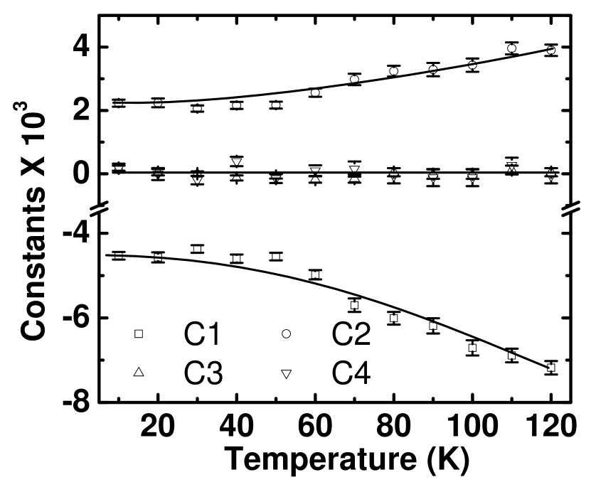
We have used equation 4 to fit RMR data for [110] sample at 10 and 300K, which were presented earlier in figure 2 and figure 3 respectively in a compact form. The quality of fit is shown for a representative set of data in figure 11. While we see a reasonably good fit to equation 4 down to 873 Oe, the angular dependence at still lower fields is characterized by a sharp drop in at due to MRPT as discussed earlier. For the 10K data, the quality of the fit is poor even at high fields () and it worsens when the field is reduced below 1574 Oe. Figure 12 shows the variation of various fitting parameters with field at 10 and 300K. In both the cases, the parameter C3 and C4 stays close to zero. This result is remarkable as it validates the fitting, because we already know and are zero for our geometry ( & ). We also note that the ratio of the quadratic () and quadruplet () coefficients remains same at 300K in the field range of 800 to 2700 Oe. At lower temperature, however, the term appearing in 4th power of remains constant where as the magnitude of the quadratic term increases with field. In figure 13 we have traced the variation of these coefficients with temperature between 10 and 120K at an applied field of 2.5 kOe. While C3 and C4 stays close to zero for all temperatures, the absolute value C1 and C2 increases with temperature. Before we discuss the significance of these coefficients (C’s), it is pertinent to discuss the angle dependent data for the [001] epitaxial films.
For the [001] film, the easy axis is along [110] where as the current is along [100] direction. This makes the direction cosines of magnetization (’s) and cosines of current (’s) with respect to cubic axis as , and , and , , and . The final expression for the resistivity in this case is;
| (10) | |||||
| where, | |||||
| (11) | |||||
| (12) | |||||
| (13) | |||||
| (14) |
In this case and where is the angle between applied field and current direction. A sketch of three vectors , and the unit vector pointing along the easy axis in a most generalized situation is given at the bottom of figure 14. Since , it turns out that in this case . Here we have assumed , where is the resistance when the field is aligned along [110] the easy axis. In figure 14 we have shown the fit of equation 10 to RMR data for [001] sample at 10 and 300K. It is evident that at 300K the model (equation 10) correctly describes the behavior of the RMR down to fields as low as 275 Oe. At still lower fields although the deviations become large, the peak and valleys of the data are correctly reproduced. The situation, however, is quite different at 10K; here even at high fields deviation from the model are evident near the maxima.
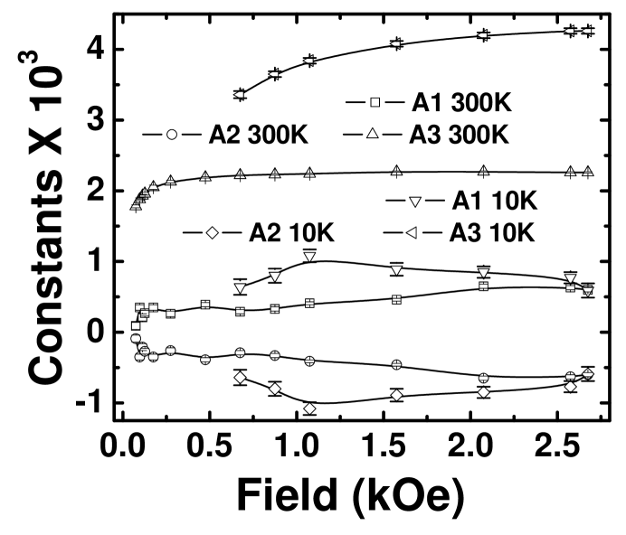
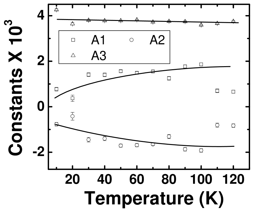
We now discuss the behavior of the coefficients and whose variation as a function of field is shown in figure 15. First of all, we note that as expected from the model under the geometry of these measurements. The coefficient at both temperatures increases with field and then becomes constant at high field. Moreover, increases by a factor of 2 at 10K. It should be noted that in equation 10 appears as a coefficient of which has extrema at and . A higher weightage of will lead to large deviations from the dependence. Figure 16 shows the dependence of coefficients and with temperature. We can clearly see that remains almost constant with temperature. The coefficient increases with temperature while decreases with temperature.
The data presented in figures 2, 3, 4 and 5 clearly show that the RMR is both temperature and film orientation dependent. From these data we also conclude that the [110] films have higher anisotropy energy then the films with [001] orientation. This becomes clear from the fact that at 300K as well as at 10K the coherent rotation of magnetization with applied field which results in dependence of RMR appears at much higher fields for [110] films then for [001] films. Secondly, a look at the AMR percentages calculated from these data shows that for the [110] films the absolute value of AMR increase with temperature while it is opposite for the [001] films. We believe that the magnetization vector of the [110] films at low temperature is strongly pinned along the easy axis due to the large anisotropy energy. At higher temperatures, the thermal energy helps in depinning and free rotation of along with the external field . This leads to enhanced RMR at higher temperatures. Of course, if the field strength is increased further, free rotation would become possible at 10K as well. The required fields, however, may be well beyond what has been used in these experiments. A direct support to this argument come from the non-saturating trend of 10K AMR of the [110] film as a function of field (figure 9). A very interesting picture emerges from the value of constants so calculated. While for the [110] film the RMR is mostly dependent on even powers of , the dependence of the RMR for the [001] films is predominantly where is the angle between applied field and easy axis of film. A qualitative explanation for this observation can be given if we refer to figure 8 where the direction of Mn-O-Mn bond of the [001] STO surface is shown. As we have stated earlier, the [110] direction is the easy axis because of the degeneracy of [010] and [100] directions in zero field. An external field applied at 450 with respect to the [110] direction lifts this degeneracy, which perhaps is the reason why MR has a strong contribution from the term with its maximum at .
A discussion on the temperature and angular dependence of RMR would remain incomplete unless we address the role of electron localization in cyclotron orbits. The orbital magnetoresistance resulting due to electron trapping is given as[14],
| (15) |
in the limit , where is the relaxation time and B⊥ the component of magnetic induction perpendicular to current I. It is expected to be negligible when carrier mean free path l is much shorter than its cyclotron orbit (rc). With the known hole density (/m3), and Fermi energy (1.8eV)[32] of LSMO and 10K resistivity and magnetic induction B(=H+4M) of the [001] film, which are 0.11 m-cm and 7500 G for [001] films respectively we obtain and . Similarly for the [110] film, the l and rc are and respectively. From these numbers it can be concluded that OMR will make negligible contribution to RMR in these films. Following Gorkom[14], the angular dependence of OMR can be written as;
| (16) |
where and is the resistivity at T = 300K. Using the and data for [001] film and equation 16 we obtain and which is much too small compared to measured RMR. From this analysis it can be concluded that the origin of angular magnetoresistance is these films is spin-orbit coupling dependent AMR effect.
4 Summary
We have carried out a comparative study of the isothermal magnetoresistance of [001] and [110]epitaxial La2/3Sr1/3MnO3 films as a function of the angle between current and coplanar magnetic field at several temperatures between 10 and 300K. The magnetic easy axis of the [001] and [110] films is along [110] and [001] directions respectively. In view of the similar texture of these two types of films, which can otherwise contribute to shape anisotropy, we conclude that the easy axis is fundamentally related to the orientation of Mn-O-Mn bonds on the plane of the substrate. The isothermal resistance and for and configurations respectively of these two type of films obeys the inequality for all fields and temperatures. However, the shows deviation from the simple dependence at low fields due to pinning of the magnetization vector along the easy axis. This effect manifests itself as a discontinuity in at and a concomitant hysteresis on reversing the angular scan. we establish a magnetization reorientation phase transition in this system and extract the H-T phase space where remains pinned. A robust pinning of magnetization seen in [110] films suggests strong in-plane anisotropy as compared to the [001] films. We have carried out a full fledged analysis of the rotational magnetoresistance of the two types of epitaxial LSMO films in the frame work of the Döring theory[20] of anisotropic magnetoresistance in metallic ferromagnet single crystals. We note that strong deviation from the predicted angular dependence exist in the irreversible regime of magnetization. A simple estimation of orbital MR in these films suggest that the RMR is dominated by spin-orbit interaction dependent anisotropic magnetoresistance.
The authors would like to thank Prof T V Ramakrishna for fruitful discussions and Mr. Rajeev Sharma for assistance in SQUID measurements. This research has been supported by a grant from the Board of Research in Nuclear Sciences, Government of India.
References
- [1] Robert C. O’Handley Modern Magnetic Materials Principles and Applications, 2000, (John Wiley and Sons, Inc., New York) pp. 579-584
- [2] T. R. McGuire and R. I. Potter, IEEE Trans. Mag. 11, 1018 (1975).
- [3] O. Jaoul, I. A. Campbell and A. Fert, J. Magn. Magn. Mater. 5, 23 (1977).
- [4] A. P. Malozemoff, Phys. Rev. B 32, 6080 (1985).
- [5] J. N. Eckstein, I. Bozovic, J. O’Donnell, M. Onellion and M. S. Rzchowski, Appl. Phys. Lett. 69, 1312 (1996).
- [6] M. Ziese and S. P. Sena, J. Phys: Condens. Matter 10, 2727 (1998).
- [7] M. Ziese, Phys. Rev. B 62, 1044 (2000).
- [8] I. C. Infante, D. Hrabovský, V. Laukhin, F. Sánchez and J. Fontcuberta, J. Appl. Phys. 99, 08C503 (2006).
- [9] X. Hong, J. -B. Yau, J. D. Hoffman, C. H. Ahn, Y. Bason and L. Klein, Phys. Rev. B 74, 174406 (2006).
- [10] K. Hamaya, R. Moriya, A. Oiwa, T. Taniyama, Y. Kitamoto Y and H. Munekata, IEEE Trans. Mag. 39, 2785 (2003).
- [11] G. Singh and R. C. Budhani, unpublished.
- [12] E. Dan Dahlberg, Kevin Riggs and G. A. Prinz, J. Appl. Phys. 63, 4270 (1988).
- [13] K. T. Riggs, E. Dan Dahlberg and G. A. Prinz, Phys. Rev. B 41, 7088 (1990).
- [14] R. P. van Gorkom, J. Caro, T. M. Klapwijk and S. Radelaar, Phys. Rev. B 63, 134432 (2001).
- [15] Clarence Zener, Phys. Rev. 82, 403 (1951).
- [16] P. W. Anderson and H. Hasegawa, Phys. Rev. 100, 675 (1955).
- [17] P. -G. de Gennes, Phys. Rev. 118, 141 (1960).
- [18] S. D. Tyagi, S. E. Lofland, M. Dominguez, S. M. Bhagat, C. Kwon, M. C. Robson, R. Ramesh and T. Venkatesan, Appl. Phys. Lett. 68, 2893 (1996).
- [19] G. Jeffrey Snyder, M. R. Beasley, T. H. Geballe, Ron Hiskes and Steve DiCarolis, Appl. Phys. Lett. 69, 4254 (1996).
- [20] W. Döring, Ann. Phys. 424, 259 (1938).
- [21] K. Senapati and R. C. Budhani, Phys. Rev. B 71, 224507 (2005).
- [22] S. Patnaik, Kanwaljeet Singh and R. C. Budhani, Rev. Sci. Instr. 17, 1494 (1999).
- [23] The easy axis of both [110] and [001] oriented films were determined by measuring M vs H, by applying fields at different angles with respect to a known crystallographic direction in the plane of the film.
- [24] L. M. Berndt, Vincent Balbarin and Y Suzuki, Appl. Phys. Lett. 77, 2903 (2000).
- [25] David Mukamel, Michael E. Fisher and Eytan Domany, Phys. Rev. Lett. 37, 565 (1976).
- [26] F. Tsui, M. C. Smoak, T. K. Nath and C. B. Eom, Appl. Phys. Lett. 76, 2421 (2000).
- [27] P. Lecoeur, P. L. Trouilloud, Gang Xiao, A. Gupta, G. Q. Gong and X. W. Li, J. Appl. Phys. 82, 3934 (1997).
- [28] P K Muduli, S K Bose and R C Budhani, J. Phys.: Condens. Matter 19, 226204 (2007)
- [29] A. P. Malozemoff, Phys. Rev. B 34, 1853 (1986).
- [30] G. Herranz, F. Sánchez, M. V. García-Cuenca, C. Ferrater, M. Varela, B. Martínez and J. Fontcuberta, J. Magn. Magn. Mater. 272-276, 517 (2004).
- [31] M. Bibes, O. Gorbenko, B. Martínez, A. Kaul and J. Fontcuberta, J Magn. Magn. Mater. 211, 47 (2000).
- [32] B. Nadgorny, I. I. Mazin, M. Osofsky, R. J. Soulen Jr., P. Broussard, R. M. Stroud, D. J. Singh, V. G. Harris, A. Arsenov and Ya Mukovskii, Phys. Rev. B 63, 184433 (2001).
Figure Captions
Figure 1: Magnetic hysteresis loops of the [110] and [001] oriented La2/3Sr1/3MnO3 films at 10K. The measurements were done under the zero field cooled condition. The direction of the applied field in these measurements was along the [001] and [110] crystallographic directions for the [110] and [001] oriented films respectively. The coercive field deduced from these measurements is 230 for the [110] and 90 Oe for the [001] samples respectively.
Figure 2: Rotational magnetoresistance R() of the [110] film measured at 300K for different values of the in-plane field. We observe a periodicity of when the external field H is 300 Oe. Below 300 Oe however, a distinct deviation from this symmetry is seen, and the peak in resistance is now shifted to . One noticeable feature of the low field ( 300 Oe) data is a sudden drop in resistance once the peak value is reached. The top left inset shows the variation of the position of first peak in the RMR data. A sketch of sample geometry is shown in the top right hand corner of the figure.
Figure 3: The R/R(0) vs graphs of the [110] film at 10K for several values of the in-plane field. Here we see deviations from a symmetric dependence on at fields lower than 1100 Oe. The inset at the top left hand corner shows the variation of peak position with field of the first peak in the RMR data. The top right hand corner shows a sketch of the measurement geometry.
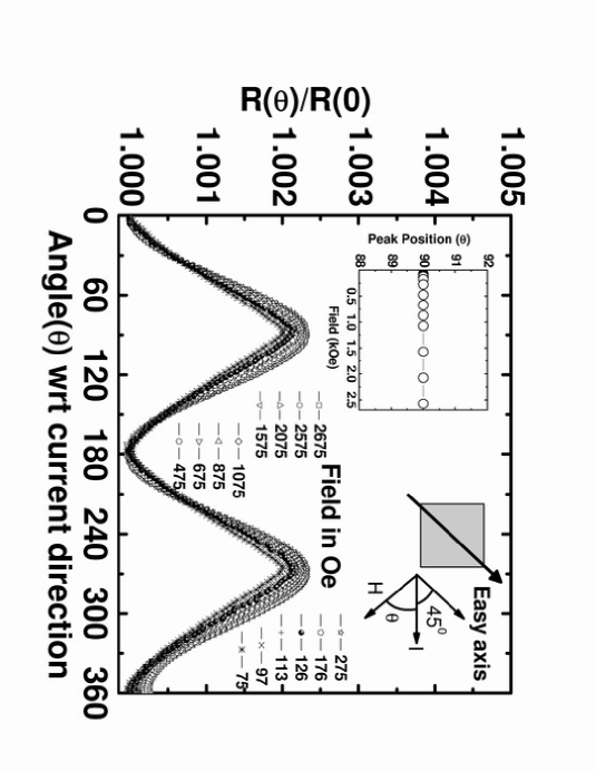
Figure 4: Rotational magnetoresistance R() of the [001] LSMO thin film measured at 300K for different values of the in-plane field. We observe a periodicity of for all external field H. The top left inset shows the variation of the position of first peak in the RMR data. A sketch of sample geometry is shown in the top right hand corner of the figure.
Figure 5: The R/R(0) vs graphs of the [001] film at 10K for several values of the in-plane field. Here we see deviations from a symmetric dependence on at fields lower than 500 Oe. The inset at the top left hand corner shows the variation of peak position with field of the first peak in the RMR data. The top right hand corner shows a sketch of the measurement geometry.
Figure 6: Hysteresis in RMR for [110] LSMO film measured at 300K and 120 Oe . The open circles and squares show the data when the field is varied in the forward (0-2) and reverse (2-0) cycles respectively.
Figure 7: H-T phase diagram for [110](open squares) and [001](open circles) films. The solid lines are hand drawn to show the most probable separation line between pinned and depinned states. These data clearly show that the pinning is much stronger in the case of [110] film than for the [001] films. A change in y-scale emphasizes this point.
Figure 8: Schematic of the ionic positions on the surface of [110] and [001] films are in the upper and lower panels respectively. For the [110] film, the two Mn ions along the [001] direction are bridged by an oxygen ion. Hence the [001] direction acts as magnetic easy axis in these films. In case of [001] the [100] and [010] direction are degenerate, hence the easy axis is along [110].
Figure 9: Variation of the RMR percentage, defined as , with field for both [110] and [001] LSMO at 10 and 300K. The RMR is negative for both films.
Figure 10: Variation of RMR percentage with temperature for [110](open squares) and [001](open circles) LSMO films between 10K and 120K. The solid lines are hand drawn depicting the most probable trend in this temperature range. The field applied in this case 2.5 kOe.
Figure 11: Fit of equation 4 to RMR data of [110] film taken at 10 and 300K(left and right hand side respectively). The dots are actual data and solid lines are fitted curve. While at 300K a reasonably good fit to equation 4 is seen down to 873 Oe, at still lower fields, the angular dependence is characterized by sharp drop of at . At these fields the torque on exerted by the external field is not strong enough for coherent rotation. For the 10K data, the quality of fit is poor even at the higher fields and worsens as it is reduced below 1574 Oe. A sketch of three vectors , and the unit vector , and of relevant angles is shown at the bottom of the figure. In our case hence and [001] is the easy axis[23].
Figure 12: Field dependence of the coefficients C1, C2, C3 and C4 obtained by fitting equation 4 to the RMR data at 10 and 300K. In both the, cases the parameter C3 and C4 stays close to zero. The result is remarkable as it validates the fitting, because we already know that due to which makes . We also note that the ratio of the quadratic () and quadruplet () term remains constant at 300K in the field range of 800 Oe to 2700 Oe. At lower temperature, however, the term appearing in 4th power of is constant where as the magnitude of the quadratic term increases with field.
Figure 13: Temperature variation of the coefficients C1, C2, C3 and C4. The coefficients C3 and C4 remain close to zero for all temperatures. The absolute value of C1 and C2 increases as we go up in temperature. The solid lines are hand drawn to indicate the most probable trend.
Figure 14: The fit of equation 10 to RMR data for the [001] sample at 10 and 300K. It is evident that at 300K the model (equation 10) correctly describes the behavior of the RMR down to fields as low as 275 Oe. At still lower fields, although the deviations become large, the peak and valleys of the data are correctly reproduced. The situation, however, is quite different at 10K, here even at the highest field deviation from the model are evident near the maxima. These deviation becomes prominent at lower fields. A sketch of three vectors , and the unit vector directed along the easy axis is shown at the bottom of the figure. In our experiment and where is the angle between applied field and current direction. The current is flowing along the hard axis and the easy axis is [110][23].
Figure 15: Field dependence of the coefficients A1, A2 and A3 obtained by fitting equation 10 to the RMR data. Here as expected from the model under the geometry of our measurements. The coefficient at both temperatures first increases with field and then becomes constant. It should be noted that in equation 10 appears as a coefficient of which has extrema at and .
Figure 16: Temperature variation of phenomenological coefficients A1, A2 and A3. In this case A3 remains almost constant throughout the temperature range. A1 increases and A2 decreases as we go up in temperature. The solid lines are hand drawn to indicate the most probable trend.