Spin transfer torques in magnetic tunnel junctions
Abstract
This chapter presents a review on spin transfer torque in magnetic tunnel junctions. In the first part, we propose an overview of experimental and theoretical studies addressing current-induced magnetization excitations in magnetic tunnel junctions. The most significant results are presented and the main observable characteristics are discussed. A description of the mechanism of spin transfer in ferromagnets is finally proposed. In the second part, a quantum description of spin transport in magnetic tunnel junctions with amorphous barrier is developed. The role of spin-dependent reflections as well as electron incidence and spin-filtering by the barrier are described. We show that these mechanisms give rise to specific properties of spin transfer in tunnel junctions, very different from the case of metallic spin-valves. In the third part, the theoretical observable features of spin transfer in magnetic tunnel junctions are derived and the validity of these results is discussed and compared to recent experiments. To conclude this chapter, we study the mechanism of spin transfer in half-metallic tunnel junctions, expected to mimic MgO-based magnetic tunnel junctions.
I Introduction
The study of the coupling between an electrical current and localized spins in transition metals, leading to giant magnetoresistance effects baibich ; binasch , has renewed our knowledge of fundamental electronics and opened wide fields of research in this domain. The idea that a spin-polarized current may in turn act on the local magnetization of such a ferromagnet have been proposed in the late 1970’s by Berger berger78 , when investigating the interaction between a domain wall and an electrical current.
However, this torque - usually called spin transfer torque (STT) - exerted by the spin-polarized current on the local magnetization requires high current densities which can only be reached in sub-micronic devices (nano-pillars, point contacts or nano-wires). The development of thin film deposition techniques, as well as electronic lithography in the early 1990’s led to the fabrication of spin-valve pillars with dimensions as small as 100100 nm2. Spin-valves, first studied by Dieny et al. dieny in 1991, consist of two ferromagnetic thin layers (less than 10 nm-thick), separated by a metallic (Cu, Al) or tunnelling (Al2O3, MgO, TaOx) spacer. One of the ferromagnet is pinned by an antiferromagnetic system so that its magnetization direction is only weakly affected by an external magnetic field.
The theoretical demonstration of spin transfer torque in metallic spin valves (SVs) ten years ago slonc96 ; berger96 gave a new breath to giant magnetoresistance related studies GMRreview , promising exciting new applications in non-volatile memories technology applSTT and radio-frequency oscillators rfSTT . A number of fundamental studies in metallic spin valves revealed the different properties of spin torque and led to a deep understanding of current-induced magnetization dynamics katine ; kiselev ; rippard ; urazhdin ; alhajdarwish . Particularly, several theoretical studies described the structure of the torque in metallic magnetic multilayers and showed the important role of averaging due to quantum interferences, spin diffusion and spin accumulation stiles02 ; autres ; jpcm .
Since the first experimental evidence of spin-dependent tunnelling jullieremeservey , magnetic tunnel junctions (MTJs) have attracted much attention because of the possibility to obtain large tunnelling magnetoresistance (TMR) at room temperature moodera . The possibility to use MTJs as sensing elements in magnetoresistive heads, as non-volatile memory elements or in reprogrammable logic gates has also stimulated a lot of technological developments aiming at the optimization of MTJs’ transport properties and their implementation in silicon-based circuitry applSTT ; ieee . Because of these applications, MTJs have been intensively studied and the role of interfaces leclair , barrier sharma , disorder tsymbal98 and impurities imp have been addressed in many publications reviewTMR . The recent achievement of current-induced magnetic excitations and reversal in MTJs huai ; fuchs has renewed the already very important interest of the scientific community in MTJs.
The recent observation of spin transfer torque in low RA (resistance area product) MTJs using amorphous huai ; fuchs or crystalline barriers ieee ; ideka opened new questions about the transport mechanism in MTJs with non collinear magnetization orientations. As a matter of fact, whereas the current-perpendicular-to-plane (CPP) transport in SVs is mostly diffusive and governed by spin accumulation and relaxation phenomena autres ; jpcm , spin transport in magnetic tunnel junctions is mainly ballistic and governed by the coupling between spin-dependent interfacial densities of states: all the potential drop occurs within the tunnel barrier. The characteristics of spin transfer torque are thus expected to be strongly different in MTJs compared to SVs.
In this chapter, we propose a description of spin transfer torque in magnetic tunnel junctions, highlighting the differences with metallic spin valves. In section II, an overview of the experiments on spin transfer torque is given as well as a description of the origin of STT in arbitrary ferromagnetic systems.
In section III, the quantum origin of spin transfer torque in MTJs is described using a simple free-electron approach. The selection of the incident electrons due to the tunnel barrier is depicted and the relaxation of the transverse and longitudinal components of the spin density (spin accumulation) is discussed. It is shown that these two effects may contribute to a non negligible field-like term (also called out-of-plane component), contrary to SVs where this term is negligible.
In section IV, we present the angular and bias dependencies of the in-plane and out-of-plane components of spin transfer torque. The important angular asymmetry usually observed in metallic systems disappears in magnetic tunnel junctions due to the reduced influence of the longitudinal spin accumulation on the transverse spin current. Then, in agreement with different theories and very recent experiments, we show that the bias dependencies of the two components of STT exhibit non linear variations due to the specific non linear transport through the tunnel barrier. We also discuss the existence of other sources which can strongly affect this bias dependence, such as the existence of interfacial asymmetry, incomplete absorption of the transverse component of spin current or, most important, emission of spin waves due to hot electrons.
Finally in section V, we present the influence of increasing s-d exchange coupling on spin torque and especially discuss the case of half metallic tunnel junctions, which might mimic MgO-based MTJs. In half metallic electrodes, the spin transfer exponentially decays near the interface still giving rise to a non zero torque on the local magnetization.
II Overview of experiments and models
The observation of spin transfer torque in magnetic tunnel junctions is only very recent (2004) due to the difficulty to obtain high-quality low RA MTJs. As a matter of fact, as we stressed out in the introduction, observing the magnetic influence of spin transfer torque requires the injection of high current densities in the MTJs, of the order of 107A/cm2 while conserving a high current polarization. Reducing the thickness of the tunnel barrier generally leads to both the reduction of TMR, as well as the appearance of pinholes pinholes (metallic conduction channel within the tunnelling barrier). The discovery of spin-filtering effect through MgO crystalline barrier butler ; butler2 allowed to obtain low resistance magnetic tunnel junctions together with high current polarization, thus fulfilling the requirements for the observation of STT in MTJs. Diao et al. diao and Huai et al. huai2 have compared the current-induced magnetization reversal in MgO-based and AlOx-based MTJ and showed that the effective polarization of the interfacial densities of states is significantly higher in MgO-MTJ (46%) than in AlOx-MTJ (22%), due to spin-filtering effects in crystalline MgO barrier. Even if the existence of such interfacial polarization is questionable discussp ; slonc05 , this estimation illustrates the significant improvement achieved with MgO-based MTJs.
II.1 Current-induced magnetization switching
II.1.1 General properties
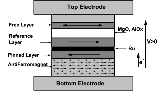
As we stated in the introduction, a magnetic tunnel junction is a tunnelling spin valve, as displayed in Fig. 1, composed of two ferromagnetic electrodes (CoFe, CoFeB) separated by a tunnelling barrier. One ferromagnetic layer (reference layer) is antiferromagnetically coupled (usually through a thin Ru layer) to a so-called "pinned layer". This pinned layer is magnetically coupled to an antiferromagnet (IrMn, FeMn). This technique, known as synthetic antiferromagnet saf , strongly stabilizes the reference layer while reducing the dipolar field emitted on the free layer. The free layer magnetization may then be oriented by an external field, while keeping the magnetization of the reference layer in a fixed direction.
The first observation of current-induced magnetization switching in magnetic tunnel junctions has been performed by Huai et al. huai and Fuchs et al. fuchs in AlOx-based low RA MTJ (RA<10m2), in nano-pillar with elliptic shape (120230 nm2 in Ref. huai ).
The influence of spin transfer torque in magnetic tunnel junctions is observed by measuring resistance loops as a function of the external applied field and the applied bias voltage , as displayed in Fig. 2. In this figure, we measured the resistance of a MgO-based MTJ, composed of CoFeB ferromagnetic electrodes. The resistance loop as a function of the external field for a fixed applied bias voltage is given in Fig. 2(a), while the resistance loop as a function of the bias voltage for a fixed external field is given in Fig. 2(b).

One observes sharp resistance jumps in Fig. 2(b) for positive and negative bias which correspond to the switching of the free layer magnetization from antiparallel to parallel and vice-versa, respectively. In this junction, the critical current needed to switch the free layer magnetization is 5106A/cm2. The drop of resistance as a function of the bias voltage is associated with a drop of TMR (see Fig. 2(c)). This drop has been attributed to spin-waves emissions by hot electrons zhang97 as well as to the energy-dependence of the density of states at the junction interfaces. Note that this drop does not exist in metallic spin valves since only Fermi electrons significantly contribute to the electrical current in metals.
Since these first observations, many efforts have been carried out in order to obtain low critical current magnetization switching in MTJs. Dieny et al. brevD , Fuchs et al. fuchs0 and Huai et al. huai3 proposed dual type MTJs, in order to reduce the critical switching current. These structures are of the type fuchs0 CoFe1/AlOx/CoFeFree/Cu/CoFe2, where CoFe1 and CoFe2 are antiparallel and the Cu/CoFe2 interface is used to reflect the minority electrons towards CoFeFree in order to enhance the spin transfer torque in this layer. With this scheme, critical current were divided by a factor 3.
Another method has been proposed by Inokuchi et al. patent . By inserting a non magnetic layer made of Zr, Hf, Rh, Ag, Au or V on the top of the free layer, it is possible to reduce the critical current by one order of magnitude and to reach critical current densities of 5 A.cm-2.
II.1.2 STT versus TMR
An interesting point has been underlined by Fuchs et al. fuchs in their pioneering experiment, when observing current-induced magnetization switching at 77 K. As displayed on Fig. 3, the magnetization of the free layer could be switched from antiparallel (black line) to parallel (red line) by applying an external current. The most interesting is that the magnetization switching occurred at a bias voltage at which the TMR was roughly zero, as shown by the arrows on Fig. 3.
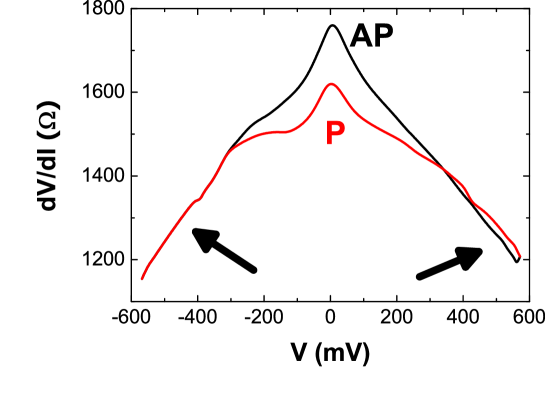
This experiment demonstrates that the TMR decrease does not prevent the spin transfer. As a matter of fact, whereas the polarization of the collecting electrode decreases when increasing the bias voltage (due to energy-dependence of the interfacial density of states as well as magnon emission), the polarization of the incident electrons is only weakly affected. Consequently, a current-induced magnetization switching may occur although the overall TMR is zero. In fact, Levy and Fert swmtj have shown that the contribution of hot electrons-induced spin-wave emission may play an important role in such systems.
II.2 Current-induced magnetization excitations
Current-induced magnetization excitations are of great interest for applications, in particular controlling the noise spectrum of read-head devices or generating hyper-frequencies. However, the generation of magnetic excitations by a polarized current in MTJs is rather difficult because of the voltage limitation of the tunnel barrier which undergo electrical breakdown when submitted to bias voltage of typically 1 V.
A first study of the "spin-diode effect" was published by Tulapurkar et al. tula , in 2005. The authors showed that the injection of a small radio-frequency ac-current into a MgO-based MTJ can generate a dc-voltage across the device. This dc-voltage appears when the frequency of the ac-current is close to the natural frequency of FMR excitations. This resonance can be tuned by an external magnetic field. By this way, Tulapurkar et al. were the first to observe a non negligible "effective field" term, , which was found to be linear as a function of the bias voltage. Recent developments of this technique were achieved by Kubota et al. kubota . They will be described in section IV.
Another technique was proposed by Sankey et al. sankeyfmr ; sankeynat . By studying the influence of spin transfer torque on the ferromagnetic resonance of the free layer, the authors were able to determine the bias dependence of the spin transfer torque. These results will be described in section IV.
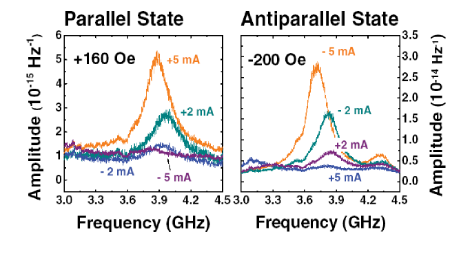
The influence of spin torque on thermally activated ferromagnetic resonance was also studied nazarov ; zhu1 . Petit et al. seb have demonstrated the influence of spin transfer torque on thermal noise in MTJs. Fig. 4 displays the thermally activated FMR spectra of a AlOx-based MTJ as a function of the injected current. In parallel configuration, the amplitude of the FMR peak increases as a function of positive current and decreases when the injected current is negative (and inversely in antiparallel configuration). Once again, the authors demonstrated the strong influence of the term on the magnetization dynamics.
II.3 Origin of spin transfer torque
After this short overview on previous relevant experiments, let us describe the physical origin of spin transfer torque. To do so, we will proceed in two steps: firstly, a phenomenological description of spin transfer will be presented, using a simple conceptual scheme; secondly, the expression of spin transfer torque in an arbitrary ferromagnet will derived from quantum mechanical consideration, justifying the phenomenological approach.
II.3.1 Phenomenological description
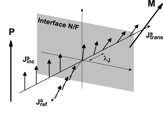
The principle of spin transfer between two ferromagnetic layers is sketched on Fig. 5. Let us consider an electrical current, spin-polarized along the direction (the electrical current may be polarized by a previous ferromagnetic layer for example). This spin-polarized current impinges on a N/F interface, where N is a normal metal (or a tunnel barrier) and F is a ferromagnetic metal whose magnetization forms an angle with , so that (). Johnson et al. JS and Van Son et al. vanson showed that an out-of-equilibrium magnetization (also called spin accumulation in diffusive systems, or spin density in ballistic systems) appears at this interface, due to the different spin-scattering rates in the N and F layers. In our system, since the impinging current is not polarized following , the rising out-of-equilibrium magnetization possesses three components. It can then exert a torque on the local magnetization of the form . Because of the fast angular precession of the electrons spin around and due to the relaxation of the spin accumulation in the ferromagnet F, the transverse component of the spin accumulation is quickly absorbed close to the N/F interface, on a length scale , usually smaller than 1 nm in metallic spin-valves stiles02 ; urzh .
Another way to understand spin transfer torque is to consider that the electrical current possesses an initial polarization, described by the spin current . One part of this impinging current is reflected by the N/F interface, giving rise to a reflected (backward) spin current . In the adiabatic regime (the electron spin precession is fast compared to the local magnetization dynamics), after a length , itinerant electrons are aligned along the local magnetization and the transmitted spin current is then . The reflected spin current being generally small, the net balance of angular moment yields the transverse component of the incident spin current: (note that transverse means transverse to ). Thus, the impinging electrons lose the transverse component of their magnetic moment which is transmitted to the localized electrons, responsible for the local magnetization . This spin transfer is translated in a torque of the form:.
Stiles et al. stiles02 have described the origin of spin transfer torque at a N/F interface, where N is a metal. The authors proposed three mechanisms giving rise to spin transfer in ballistic systems. First, the spin dependence of the interfacial reflection and transmission coefficients induces a discontinuity of the spin current so that one part of the transverse component of spin current is absorbed at the interface. This discontinuity gives rise to a torque in the plane (, ) which tends to align and . Secondly, the spin precession around the local magnetization , after averaging over the whole Fermi surface, gives rise to the complete absorption of the transverse spin current on a length scale of the order of nm. Finally, after reflection by the interface, the electron spin forms an angle with both and . This spin rotation yields the appearance of another component of the spin torque, perpendicular to the plane (, ) and called out-of-plane torque.
Thus, these three contributions give rise to a torque exerted by the spin accumulation on the local magnetization, written as:
| (1) |
where and are the in-plane and out-of-plane torque amplitudes. Note that in the first theories of spin transfer torque by Slonczewski slonc89 ; slonc96 ; slonc02 and Berger berger96 ; berger01 , the authors only derived because they considered that the electron spin remains in the (, ) plane, as corroborated by calculations stiles02 . These theories apply to metallic spin valves where, due to the small length , spin transfer is assumed to take place very close to the interface fertstt . However, Edwards et al. edwards have derived a sizable out-of-plane torque in metallic spin-valves using non equilibrium Green’s functions and interestingly, Zhang et al. zlf have demonstrated that taking into account the spin precession in the transport model significantly enhances the term. In magnetic tunnel junctions, both and term arise from different mechanisms that will be described in section III.
Injecting the spin transfer torque in the Landau-Lifshitz-Gilbert (LLG) equation, one obtains the modified LLG equation, describing the magnetization dynamics of the free layer, submitted to both an external field and a spin-polarized electrical current:
| (2) |
where is the gyromagnetic ratio, is the Gilbert damping and is the effective field, including the anisotropy field, the demagnetizing field and the external applied field. From Eq. 2, the out-of-plane torque acts as an effective field while the in-plane torque acts as an effective (anti-)damping. As a function of its sign, may excite or damp magnetic excitations in the magnetization , whereas only affects the energy surface of the ferromagnetic layer. Different magnetic behavior may be observed: magnetization switching from a stable state to another, stabilization of magnetic states at low energy minima, or magnetic excitations (coherent and incoherent precessions).
II.3.2 Spin transfer in an arbitrary ferromagnet
All along this section, we consider the s-d model in which two populations of electrons coexist: itinerant electrons (sp-type or itinerant d-type electrons) and localized electrons (d-type mainly). The localized electrons give rise to the local magnetization of the ferromagnet. We also assume that the d local moments remain stationary. This model applies to the electronic structure of ferromagnetic electrodes whose compositions lie on the negative slope side of the Slater-Néel-Pauling curve stearns73 (Ni, Co, NiFe, CoFe).
Itinerant electrons dynamics
The motion of itinerant electrons in the ferromagnetic materials are represented by the non-relativistic single electron Hamiltonian including coupling:
| (3) |
where the first and second terms are the kinetic and potential energies, while the third term is the exchange energy, being the unit vector of the local magnetization due to the localized electrons and the s-d exchange constant. Let us define the local spin density and the local spin current density of itinerant electrons as
| (4) |
| (5) |
and the temporal derivative of the spin density is:
| (6) |
where is an arbitrary 2-dimension Hartree-Fock wave function. The two dimensions refer to up () and down () spin projection of the Hartree-Fock wave function.
From the time-dependent Schrodinger equation , we obtain the spin density continuity equation:
| (7) |
To correctly describe the ferromagnetic system under consideration, one should add the interactions between electrons and lattice, for example. In diffusive regime, one can introduce a spin relaxation term which depends on the spin density zhangli :
| (8) |
Eqs. 7 and 8 are of great importance to understand the role of spin transport in STT. One can see that the temporal variation of the spin density (or spin accumulation) arises from the contribution of three sources: the spatial variation of spin current density, the torque exerted by the background magnetization and a scattering source which acts as a spin sink.
Localized electrons dynamics
The Hamiltonian of a single localized spin submitted to a time dependent external field and to an external current flow is:
| (9) |
where is the Lande factor, is the Bohr magnetron, is the localized spin, is the external magnetic field, m is the out-of-equilibrium spin density of the itinerant electrons and is the effective field due to the combination between the external field and the itinerant electron spin density. Applying Ehrenfest theorem miltat leads to
| (10) |
where <> denotes averaging over all the localized states, . We can rewrite this equation as:
| (11) |
The first term includes all the interactions with magnetic fields, like external field, magnetocrystalline anisotropy. The second term arises from the presence of itinerant electrons. In order to take into account the damping of the localized spin, one has to consider a more complete Hamiltonian that includes many body interactions which leads to the usual Landau-Lifshitz-Gilbert equation:
| (12) |
where is the phenomenological Gilbert damping coefficient.
Modified LLG dynamic equation
Averaging Eq. 12 over all the electrons of the structure and setting , and , we obtain the modified LLG equation:
| (13) |
Here M is the local magnetization, m is the out-of-equilibrium spin accumulation or spin density of itinerant electrons, and
| (14) |
where is the anisotropy field, is the exchange constant, and is the demagnetization field. The term proportional to is a torque exerted by the spin accumulation m on the local magnetization M, similar to the one given in Eq. 8. It is interesting to note that only the transverse spin accumulation m has an influence on the background magnetization state in the form of a torque along two axes:
| (15) |
where P is the unit vector parallel to the magnetization of the pinned layer and M is the unit vector parallel to the magnetization of the free layer. The first term in the right-hand-side of Eq. 15 is called the field-like term (or out-of-plane torque, or current-induced interlayer exchange coupling) and the second term is the usual Slonczewski term (or in-plane torque).
The time scale of itinerant spins dynamics is two orders of magnitude shorter than the time scale of the background magnetization dynamics. So one can consider, in a first approximation, that the itinerant spins can be described by the steady state equation (see Eqs. 7 and 8):
| (16) | |||
| (17) |
Eqs. 16-17 imply that the spatial transfer of spin density per unit of time from the itinerant -electrons to the localized -electrons (left-hand side terms) is equivalent to a torque exerted by the transverse spin accumulation on the local magnetization (right-hand side terms), modulated by the relaxation of the spin accumulation in diffusive regime.
II.4 Theories of spin transfer in magnetic tunnel junctions
Slonczewski first proposed a free electron model of spin transport in a MTJ with an amorphous barrier slonc89 , deriving TMR, in-plane spin transfer torque and zero bias interlayer exchange coupling (IEC). This first model only considered electrons at Fermi energy, neglecting all non-linear tunnel behaviors (consequently, the out-of-plane torque was found to be zero). In a two band model, the torque was written as:
| (18) |
where is the barrier wave vector, are the Fermi wave vectors for majority and minority spins, is the barrier thickness and , the bias voltage across the junction. Note that this model is restricted to rectangular barrier, so very low bias voltage. More recently, combining Bardeen Transfer Matrix formalism (BTM) and his previous results on the relation between torques and spin currents slonc02 , the author proposed a more general formula for in-plane torque in magnetic tunnel junctions slonc05 ; slonc07 :
| (19) | |||
| (20) | |||
| (21) |
where and are the orbital wave functions for right and left interface. This relation stands for electrons whose energy is close to the Fermi energy. The author underlined interestingly that Eq. 19 may be simplified if the integrals can be separated in the form:
| (22) |
where is the density of states at the left (right) interface, for spin projection . In this case, it is straightforward to see that the torque exerted on the right layer is reduced to:
| (23) |
where is the interfacial polarization of the density of states, as defined by Julliere jullieremeservey . This leads to a bias asymmetry of the spin transfer torque, since the polarization is bias dependent for only one direction of the applied voltage. The condition of this separability has been discussed by Slonczewski slonc05 , Belaschenko et al. belashchenko and Mathon et al. umerski1 . These authors have suggested that the phase decoherences, induced by disorder in realistic junctions, could reduce the polarization factors to a product between the interfacial densities of states. It seems that this assumption is valid in magnetic tunnel junctions with not so thin barriers, especially in amorphous AlOx-based MTJs.
Theodonis et al. theo ; kalitsov recently presented a tight-binding model (TB) of MTJs, taking into account more realistic band structures than the usual free electron model. These studies showed that the in-plane torque should present an important bias asymmetry while the out-of-plane torque should be of the same order of magnitude with a quadratic dependence on the bias voltage. This is in agreement with recent studies of Wilczynski et al. barnasstt and Manchon et al. manchon , based on free electron model, as discussed in this chapter.
The role of magnons have been addressed by Levy et al. swmtj and by Li et al. prlli . It was shown that magnons emission may strongly influence the bias dependence of spin transfer torque contributing to modify the absorption length . This mechanism will be discussed in section IV.
Finally, note that all these theories assume amorphous barriers and a plane wave description of the transport, although most of the experiments are carried out on crystalline MgO-based MTJs. A recent publication from Heiliger et al. heiliger addresses the characteristics of spin transfer torque in Fe/MgO/Fe crystalline junctions. The dominant contribution of symmetry strongly influences spin torque feature.
III Quantum origin of spin torque in magnetic tunnel junctions
We will now describe the spin transport in magnetic tunnel junctions. Although most of the experiments are nowadays performed in crystalline MgO-based MTJ, one can get a first insight of TMR and spin torque by simply considering a free electron model of magnetic tunnel junctions.
We first introduce the free-electron model, and then depict the spin transport in a MTJ with non-collinear magnetization directions. Afterward, we will describe the role of the barrier on the spin transfer torque. Finally, the origin of the torques and coupling between the two ferromagnetic layers will be explained.
III.1 Free electron model
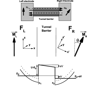
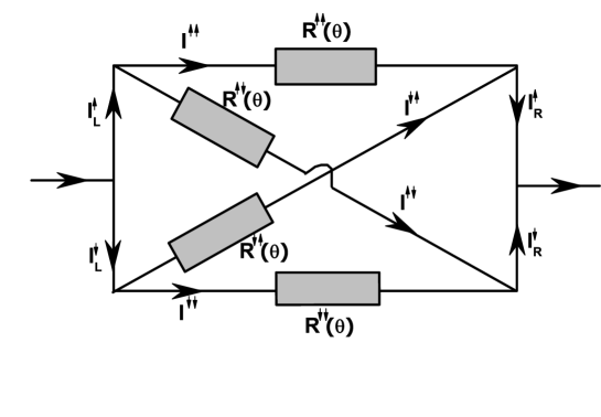
The basis of our calculation is depicted in the top panel of Fig. 6. The out-of-equilibrium magnetic tunnel junction is modeled by a "conductor" (in the sense that the tunnel barrier is not infinite) linking two magnetic reservoirs ( and ) with non collinear magnetizations and with different chemical potentials and datta (). A bias voltage is applied across this "conductor". One has to consider all electrons with majority spins (solid arrows) and minority spins (dotted arrows), originated from left (rightward arrows) and right electrodes (leftward arrows). In low bias limit (), the charge transport can be approximately determined by the electrons originated only from the left electrode with an energy between and .
In our case (middle panel of Fig. 6), the magnetic tunnel junction is composed of two ferromagnetic layers, and (made of the same material, for simplicity), respectively connected to the left and right reservoirs and separated by an amorphous tunnel barrier. The x-axis is perpendicular to the plane of the layers and the magnetization of is oriented following z: . The magnetization of is in the (x,z) plane and tilted from by an angle . In this configuration, the spin density in the ferromagnetic layer possesses three components : . In (we obtain the same results considering ), the transverse components are and , where are the Pauli spin matrices and <> denotes averaging over orbital states and spin states, i.e. averaging over electrons energy , transverse momentum and spin states. The transverse spin density in the left layer is then given by :
| (24) |
In other words, the in-plane torque is given by the imaginary part of , while the out-of-plane torque is given by its real part. One can understand the product as a correlation function between the two projections of the spin of the impinging electrons. In ballistic regime, the spin of an electron impinging on a ferromagnet with a spin polarization tilted from the background magnetization precesses around this magnetization stiles02 ; kalitsov . Locally, its two projections and following the quantization axis (defined by the background magnetization) are then non-zero. As a result, the electron contributes locally to the transverse spin density and . If the electron spin is fully polarized parallel or antiparallel to this magnetization, no precession occurs and its contribution to the transverse spin density is zero.
We remind that we defined majority (minority) states as the spin projection parallel (antiparallel) to the magnetization of the left electrode. Therefore, is the fraction of electrons whose spin is following (real part) and (imaginary part) in spin space.
In Keldysh out-of-equilibrium formalism datta ; keldysh , the conductivity is calculated considering the contribution of the electrons originating from the left reservoir and from the right reservoir (top panel of Fig. 6). The out-of-equilibrium Green function (or Keldysh Green function) is defined as a superposition of these two contributions:
| (25) |
where are the electron wave functions originating from the left (right) reservoir at the location and time and are the Fermi distribution functions in the left and right reservoirs.
Thus, the Schrodinger equation of the magnetic tunnel junction is:
| (26) |
where the vector in Pauli matrices space : , is the electron energy, is the spin-independent potential along the junction:
We consider that the potential drop occurs essentially within the barrier and we assume the bias voltage is low compared to the barrier height (). This allows to use WKB approximation to determine the wave functions inside the barrier. Furthermore, the free electron approximation implies parabolic dispersion laws which also restricts our study to low bias voltage.
In the 2-dimensional Hartree-Fock representation, spin-dependent current and spin density are defined using the out-of-equilibrium lesser Keldysh Green function:
| (27) | |||||
where , , and is the Fermi distribution at 0 K. In-plane () and out-of-plane torques () can now be determined from Eq. 24, whereas spin-dependent electrical current densities are calculated from the usual local definition:
| (28) | |||
| (29) | |||
| (30) | |||
| (31) |
and are the energy-resolved local density-of-states (LDOS) for up- and down-spins respectively, whereas and give the density of up- and down-electrons at location along the structure.
To illustrate the above calculation, we use material parameters adapted to the case of Co/Al2O3/Co structure: the Fermi wave vectors for majority and minority spins are respectively Å-1, Å-1, the barrier height is eV, the effective electron mass within the insulator is =0.4 bratkovsky and the barrier thickness is =0.6 nm. These parameters have been choosen to fit the experimental I-V characteristics of the magnetic tunnel junctions studied in Ref. seb . In all this section, the magnetizations form an angle of =90°. We will justify this choice in the following.
III.2 Spin transport in a MTJ
Although spin-dependent tunnelling is a well known process, the description we give here is of great importance to understand the specific characteristics of spin transfer torques in tunnelling transport. In this part, we will consider the linear approximation in which the bias voltage is low enough so that the current is due to Fermi electrons injected from the left electrode. When the electrodes magnetizations are non collinear, the electrons are no more described as pure spin states, but as a mixing between majority and minority states. For example, let us consider one electron from the left reservoir, initially in majority spin state, impinging on the right electrode (see Fig. 7 - step 1). The first reflection (step 2) at the interface do not introduce any mixing since the insulator is non magnetic. However, when (the transmitted part of) this electron is reflected or transmitted by the second interface (step 3), the resulting state in the right electrode is a mixing between majority and minority states since the quantization axis in the right electrode is different from the quantization axis in the left electrode. Then, the transmitted spin is reoriented and precesses (step 4) around the magnetization of the right electrode. Furthermore, the reflected electron (step 5) is also in a mixed spin state and precesses around the left electrode magnetization. In other words, after transport through the barrier, the electron spin is reflected/transmitted with an angle. This reorientation gives rise to spin transfer torque.

Note that there is no reason why the electron spin should remain in the plane of the electrodes magnetization. We will see that after the reorientation, the electron spin possesses three components in spin space (and so two transverse components).
III.3 Incidence selection in an amorphous barrier
III.3.1 -selection due to tunnelling
It is well know that in non magnetic tunnel junctions, the transmission of an impinging electrons dependent on its incident direction. As a matter of fact, the effective barrier thickness involved in the tunnelling process is larger for grazing incidence than for normal incidence. The transmission coefficient decreases exponentially with the in-plane wave vector , so that only electrons whose wave vector is close to the perpendicular incidence significantly contribute to the tunnelling transport.
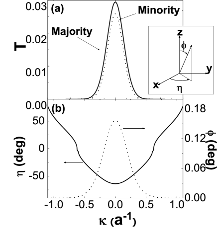
Furthermore, in magnetic tunnel junctions, the transmission coefficients also depend on the spin projection of the electrons, as well as on the magnetic configuration of the ferromagnetic electrodes. This "-selection" is illustrated in Fig. 8(a). As discussed previously, when the electrodes magnetization are non-collinear, the spin of an impinging electron, originally in a pure spin state, is reoriented after reflection so that the reflected state is in a mixed spin state. In our case, only the reflection coefficients of the conserved spin part are reported in Fig. 8(a).
Note that only a very small part of the injected polarized wave is flipped during the tunnelling process. However, this does not mean that spin transfer torque is small in MTJs, since only coherent mixed states contribute to the transverse spin density, which is responsible of the spin transfer torque.
III.3.2 Spin selection due to ferromagnets
Following the previous discussion about spin reorientation (see Fig. 7), it is possible to deduce the angles at which the electron spin is reflected by the barrier. We define the azimuthal angle and the polar angle as indicated in the insert of Fig. 8(a).
Fig. 8(b) displays these angles as a function of the in-plane wave vector . The azimuthal angle varies between -64∘ to +77∘ while the polar angle remains very small (less than 0.2∘, which means that the electron spin stays very close to the quantization axis, as discussed above). At Å-1 (corresponding to ), which indicates that the effective spin density lies in the plane of the magnetizations . Finally, the polar angle does not vary with the distance, which means that the reflected electron spin precesses around with a small angle . A "bulk" spin transfer results from the interferences of all the reflected electrons.
The strong dependence of as a function of the in-plane wave vector , combined with the -selection close to the normal incidence (see Fig. 8(a)), implies that the effective spin of the transmitted electrons possesses an important out-of-plane component. In other words, the effect of the spin-dependent tunnelling is to strongly enhance the out-of-plane component of the spin torque, compared to metallic spin valves. As a matter of fact, in metallic spin-valves, the whole Fermi surface contributes to the spin transport so that the effective angle is very small stiles02 and correlatively the out-of-plane torque is negligible.
Fig. 9 shows the dependence of the angles as a function of the s-d exchange constant for perpendicular incidence . Quite intuitively, the precession angle increases with whereas the initial azimuthal angle decreases in absolute value with . The spin-filtering effect (the selection between majority and minority spin during the reflection process) increases with so that the reflected spin direction gets closer to the plane of the magnetizations.

III.4 Spin filtering in crystalline structures
Besides the two fundamental tunnelling selection mechanisms discussed above, an additional spin filtering mechanism was proposed by Butler et al. butler ; butler2 which takes advantage from the electronic structure of both electrode and insulator crystalline materials comprising MTJ. It is based on the fact that only electrons of certain wave function symmetries can easily propagate through the barrier. For instance, in Fe(001) only the majority spin channel has electronic states with symmetry at the Fermi level which in it turn includes -like character in it. On another hand, the same band in MgO(001) forms an evanescent state in the MgO gap with the smallest decay rate butler ; butler2 . As a result, Fe|MgO|Fe(001) tunnel junction has a very large conductance in parallel state due to fairly transparent majority channel at . Antiparallel magnetizations configuration, on a contrary, is low conductive since the symmetry states does not exist in the minority band structure around the Fermi level butler ; butler2 .
Spin transfer torque is nowadays usually observed in MgO-based crystalline junctions, whereas only few theoretical work has been done on spin transfer in crystalline structures. The first theoretical studies of Heiliger et al. heiliger on MgO-based MTJs indicate a dominate contribution of the symmetry on spin transport which may affect the observable characteristics of STT, as discussed in section IV.
III.5 Torques and coupling
The mechanisms we previously described are at the origin of spin-dependent plane waves in the MTJ. The interferences between these waves give rise to an out-of-equilibrium magnetization m which couples the ferromagnetic electrodes.
In the linear regime under consideration, the three components of spin density in the left electrode can be described as follows:
| (32) | |||
| (33) | |||
| (34) | |||
| (35) |
where , and are coefficients depending on the junction parameters and on the bias voltage jpcm and are the wave vectors of majority and minority spin, respectively.
Considering in Eqs. 32-35, two components can be distinguished : the first one is proportional to , and due to the interference between the incident wave with majority (resp. minority) spin and the reflected wave with minority (resp. majority) spin; the second one is proportional to and due to the interference between the reflected waves with majority and minority spins. We note that the first components of and are complex conjugated so that their sum is real. Then, the interference between the incident wave with majority spin and the reflected wave with minority spin does not contribute to in-plane torque but only to out-of-plane torque. In-plane torque is then generated by the coherent interferences between reflected electrons with opposite spin projection ().
Concerning , it is composed of one component proportional to , one component proportional to and one constant as a function of . The two formers are due to the interference between waves having the same spin projection but with opposite propagation direction while the latter is due to interference between waves having the same spin projection and the same propagation direction.
Fig. 10 displays the details of the spin density components , et (described in Eq. 32) in the left electrode as a function of , when V. possesses a quite complex behavior with two periods of oscillation (the dashed lines show the envelope of the curve), whereas is reduced to a single oscillation (The oscillation period vanishes when summing the contribution of majority and minority spins); oscillates around mean values represented by horizontal dashed lines.

Note that the conservative part of the out-of-plane torque (interlayer exchange coupling at zero bias jfv ; tiusanjpcm ) is only proportional to . But at non zero bias, the dissipative part of the out-of-plane torque is proportional to both and .
IV Observable properties
Up to now, in order to describe the quantum origin of spin torque in MTJ, we focused on Fermi electrons and low bias voltage. To depict the observable properties of spin transfer torque in MTJ, we should take into account all the electrons from the left and the right electrodes so as to include non-linear processes.
IV.1 Angular dependence
Fig. 11(a) shows the normalized in-plane and out-of-plane components, and , as a function of the angle between the electrodes magnetizations, at and V. The normalized torques are defined as:
It clearly appears that both components are proportional to (the deviation from is smaller than 10-4). This dependence is strongly different from what was predicted in metallic spin valves autres ; jpcm ; slonc02 (see Fig. 11(b)) and has been attributed slonc05 to the single-electron nature of tunnelling.
As a matter of fact, in metallic spin-valves, the spin accumulation, due to spin-dependent scattering at the interfaces, modifies the potential profile seen by the electrons. This effect is due to the multi-electrons nature of diffusive transport, since the transport of one electron spin is affected by the spin accumulation rising from the whole spin polarized current. This spin accumulation strongly influences the angular dependence of the stack resistance and spin transfer torque jpcm .

On the contrary, in magnetic tunnel junctions, because of the important height of the tunnel barrier ( eV), all the potential drop occurs inside the insulator and the spin accumulation (i.e. the feedback of the current-induced longitudinal spin density on the spin current) is negligible. In this case, the angular dependence of torque is determined by the angular dependence of the transmission matrix, as discussed in Ref. slonc05 and yields a sine shape. In the following, we will estimate the spin density for .
Note that, at zero bias, the out-of-plane torque is still non-zero, contrary to in-plane torque. The conservative part of the out-of-plane torque (interlayer exchange coupling at zero bias) comes from the contribution of electrons located under the Fermi level jfv ; tiusanjpcm . At zero bias, the currents from left and right electrodes are equal, but the electron propagation still corresponds to the scheme shown in Fig. 7: the mixing between majority and minority states induces a transverse component in the spin density.
IV.2 Decay length of spin density
As discussed in section II.3.2, spin transfer torque is estimated from the transverse component of the spin density. This spin density (or spin accumulation in diffusive systems) usually decays due to quantum interferences or spin-dependent scattering, so that spin torque is generally assumed to be an interfacial phenomenon.
IV.2.1 Ballistic interferences
In the present model, no spin-diffusion is taken into account and the Fermi surface is assumed spherical. Fig. 12 displays the two components of transverse spin density as a function of the location in the left electrode. The interference process between polarized electrons yields a damped oscillation of the in-plane component (giving rise to the out-of-plane torque) as presented in Fig. 12(a). We can distinguish two periods of oscillation and whereas at zero bias, only appears (see inset of Fig. 12(a)). This can be easily understood by considering electrons from left and right electrodes. The transverse spin density in the left electrode due to electrons from the right electrode is:
| (36) | |||
| (37) |
where are coefficients depending on the junction parameters and on the bias voltage jpcm . It is now possible to show that in the general expression of transverse spin density
the terms proportional to vanish at zero bias due to the cancellation of contribution of electrons from the left and right reservoirs at zero bias voltage () so that reduces to terms proportional to manchon . Furthermore, these last terms only give a real component since, as discussed above, the majority and minority components of (giving rise to the in-plane torque) compensate each other. Consequently, at zero bias, only the conservative part of the out-of-plane torque (zero bias interlayer exchange coupling) exists, due to the interference between incident and reflected electrons with opposite spin projection jfv ; tiusanjpcm . But when the bias voltage is non zero, the transport becomes asymmetric and the terms proportional to do not compensate each other anymore which leads to two periods of oscillations as shown in Fig. 12(a).

In-plane component of spin transfer torque, proportional to , exits only at non zero bias and possesses only one period of oscillation (see Fig. 12(b)). It is worthy to note that the transverse components of spin density is damped by 50% within the first nanometers, and that the amplitude of the out-of-plane torque is of the same order than the in-plane torque. This decay length is very large compared to previous theoretical predictions stiles02 ; slonc02 and experimental investigations on SV urzh . As a matter of fact, the ballistic assumption holds for distance smaller than the mean free path ( nm in Co). In realistic devices, spin diffusion processes should increase the decay of the transverse components of spin density.

Finally, Fig. 13 shows the out-of-equilibrium longitudinal spin density defined as . oscillates and asymptotically reaches a non zero value. This means that when the bias voltage is turned on, a non equilibrium spin accumulation builds up. However, this effective spin accumulation is very small ( electron/atom) and cannot influence spin current building. Therefore, neglecting the role of longitudinal spin accumulation (spin density) in MTJ is justified.
IV.2.2 Spin scattering mechanisms
In real magnetic tunnel junctions, one should take into account spin-flip processes induced by spin-orbit coupling as well as hot electrons-induced spin-waves emissions that occur within the diffusive ferromagnetic electrodes. Spin-orbit induced spin-flip scattering (Elliott-Yafet mechanism elliott ; yafet ) as well as spin-wave scattering fert69 lead to spin-diffusion length, of 15-30 nm in usual ferromagnetic electrodesbass . This spin-flip should increase the spatial decay rate of the spin density by a factor of .
Spin-flip scattering by hot-electrons induced spin wave is a spin-flip mechanism that specifically occurs in magnetic tunnel junctions zhang97 . In tunnel junctions, at non zero bias, spin-polarized electrons from the left electrode impinge to the right electrode with an energy higher than the local Fermi energy: they are called "hot electrons". These hot electrons relax towards the Fermi level by inelastic scattering involving phonon and magnon emission. Following the Fermi Golden rule, this spin-waves emission increases with temperature and energy of the hot electrons. Li et al. prlli have shown that the spin-diffusion length due to this mechanism is written:
| (38) |
where is the ferromagnetic exchange constant and the Fermi energy. The authors find a spin-diffusion length of about 0.5-2 nm for reasonable parameters. This demonstrates the essential role of magnon emissions in magnetic tunnel junctions.
IV.2.3 Real Fermi surfaces
In order to more accurately describe spin-dependent transport throughout crystalline barriers butler ; butler2 (in particular MgO-based MTJs), the role of defaults in the barrier tsymbal , or interfacial states effects, it is necessary to go beyond the free electron model and consider the real band structure of the stack.
First principle studies of realistic Co/Cu interfaces zwier (so, metallic spin-valves) showed that the mismatch of the electronic structure at the interface for spin down electrons strongly reduces the transverse component of spin density. As a matter of fact, the spin-dependent transmission at the interface becomes more complex. In particular, the electron phase distribution becomes broad and asymmetric stiles02 . This leads to a rapid interfacial decay of the transverse spin accumulation in metallic spin-valves. In MTJ, the non spherical nature of the spin-dependent Fermi surface belashchenko ; butler ; tsymbal should also dramatically alter the transverse spin density. This could explain the fact that the amplitude of spin torque in the free-electron model we proposed is two orders of magnitude higher than in experiments.
Heiliger et al. heiliger recently studied the spin transfer torque in Fe/MgO/Fe crystalline tunnel junction. The authors showed that the interfacial spin density decay is even stronger in this type of MTJ than in metallic spin-valves. This decay is attributed to the dominant contribution of electrons for which Fe behaves as a half-metal with respect to this symmetry. Spin transfer torque arising from the interferences between majority (propagative states) and minority (evanescent states) electrons, is localized close to the MgO/Fe interface. This point will be addressed in more details in section V.
IV.3 Bias dependence
IV.3.1 Free electron model
The bias dependence of in-plane and out-of-plane torques in MTJ also presents strong differences with metallic spin-valves. We first calculate the total spin torque exerted on the left electrode. Following the definition of Ref. slonc96 and Ref. theo , the total torque is:
| (39) |
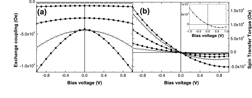
Fig. 14 displays the total out-of-plane (a) and in-plane (b) torques as a function of the applied bias voltage, for different values of the s-d exchange parameter . Consistently with Theodonis et al. theo , the out-of-plane torque is quadratic whereas the in-plane torque is a combination between linear and quadratic bias dependence.
Finally, note that a change of sign of spin transfer torque at high positive bias voltage is expectedtheo . The in-plane torque change of sign should be observed in MTJ with low enough barrier height and high breakdown voltage (MgO seems a good candidate). Nevertheless, more technological development are needed to fabricate such junctions.
However, Eq. 39 assumes that all the transverse spin density is relaxed within the free layer. In other words, the initially misaligned incident electron spin eventually aligns on the local magnetization within the free layer. This assumption seems to be valid, regarding the previous discussions. Nevertheless, considering weak spin-diffusion processes as well as non-half metallic junctions (i.e. not like Fe/MgO/Fe), one may assume that the electron spin is not fully aligned on the local magnetization when leaving the free layer. This assumption may be valid in magnetic semiconductor-based tunnel junctions, where the spin-diffusion length is very largeasga . Fig. 15 displays the bias dependence of out-of-plane and in-plane torques for different integration depths (namely, different layer thicknesses):
| (40) |
The bias dependence can change drastically and the out-of-plane torque can even change its sign (note that the in-plane torque keeps its general shape). These dependencies are strongly affected by the tunnel barrier characteristics and one should be careful in the analysis of bias dependence.
IV.3.2 Circuit theory
Slonczewski slonc05 proposed a circuit model to describe magnetic tunnel junctions in the general case, without restriction of the band structure of the electrodes and of the barrier. Fig. 16 shows the schematics of this model. Theodonis et al. theo have demonstrated that this model reproduces well the bias dependence of the in-plane torque. If one considers the two pure spin states in the quantification axis of the left electrode and , they can be decomposed on the eigenstates of the right electrode in the following manner:
| (41) | |||
| (42) |
where is the angle between the magnetizations of the electrodes. Then, the probability for an electron spin in the left electrode to be observed in a spin projection in the right electrode is . The associated resistances indicated on Fig. 16 are inversely proportional to this probability, thus leading to:
| (43) | |||
| (44) |
Using the expression of in-plane spin transfer torque derived by Slonczewski slonc05 :
| (45) |
where is the current density of the spin projection in L(R) electrode, we then find:
| (46) |
where are the interfacial spin current densities when the magnetizations are in antiparallel (parallel) configuration. Theodonis et al. theo claimed that this relation is independent of the electronic structure or of the adopted description (free electron, tight-binding…). As a matter of fact, the insert of Fig. 14 shows the STT calculated using Eq. 39 (solid line) and using Eq. 46 (symbols), which are in very good agreement. From Brinkman’s model brink , the authors demonstrated that the component is the superposition of a linear contribution and a quadratic contribution as a function of the bias voltage.
As a matter of fact, Brinkman et al. brink have showed, from a free electron model, that the current density flowing across a non magnetic tunnel junction whose barrier is asymmetric and submitted to a bias may be described by:
| (47) | |||
| (48) | |||
| (49) |
where and are the barrier height at the left and right interfaces, measured from the bottom of the conduction band. and are determined in Ref. brink . In the case of a magnetic tunnel junction, Eq. 47 apply to each spin projection. When the magnetizations are parallel, the MTJ behaves like a symmetric tunnel junction for each spin projection and , . On the contrary, if the electrode magnetizations are antiparallel, the MTJ behaves like a asymmetric tunnel junction for each spin projection and , . The spin density is then:
| (50) | |||
| (51) |
By this way, Theodonis et al. theo demonstrated that the general form of the Slonczewski term is . The balance between the two bias dependencies, quadratic and linear, may be modified by varying .
Note that the circuit model cannot describe the second component of the spin transfer, since it makes two restrictive assumptions: i) during the transport, the electron spin remains in the magnetization plane ( - see Fig. 9) and ii) the spin current is completely absorbed at the interface (no precession is taken into account, since the electron spin is instantaneously reoriented along the local magnetization). These two hypothesis ignore the effects which give rise to the out-of-plane torqueslonc05 .
IV.3.3 Asymmetric junction
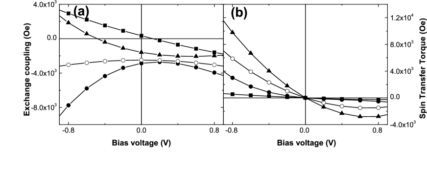
Wilczynski et al. barnasstt recently showed that the bias dependence of the torque is strongly affected by the symmetry of the junction. Considering two different ferromagnetic electrodes (different thickness or different s-d exchange coupling), the authors show that the bias dependence may be very different from the usual parabolic and second order bias dependence depicted in Fig. 14.
Slonczewski et al. slonc07 recently proposed a study of the influence of elastic and inelastic tunnelling in the spin transfer torque characteristics. This discussion is restricted to the in-plane torque and the out-of-plane component is predicted to be in the second order of bias voltage.
IV.3.4 Role of magnons emissions
Magnons emission are also expected to play an important role in spin-dependent tunnelling transport. As a matter of fact, Zhang et al. zhang97 proposed that impinging electrons with energy higher than the Fermi level can emit spin waves by flipping their spin near the MTJ interface, leading to TMR drop as a function of the applied bias voltage. Levy and Fertswmtj recently suggested that the partial depolarization of spin-current by spin-waves emission may give rise to a torque on the local magnetization, and consequently significantly contribute to spin transfer torque. We give here a summary of the picture proposed in Ref. swmtj .
The authors considered a system similar to Slonczewski’s slonc89 where the barrier is rectangular and submitted to low bias voltage. In this case, we saw that only in-plane spin transfer torque appears (see Eq. 18). The authors showed that in the case of spin-waves emission, the in-plane torque possesses four sources:
| (52) |
where the four terms stand for the elastic torque (usual in-plane torque), the emission of interfacial magnons and the emission of bulk magnons acting on the transversal and longitudinal component of the local magnetization.
Interfacial magnons
Magnons in general can only be excited by electrons whose energy is higher than the Fermi level and, their energy is . This leads to the formulation of the torque due to interfacial magnons excitations, exerted on the layer:
where are the numbers of spins per unit area at the interface (in the left and right electrodes, respectively), are the interfacial spin polarizations, are coefficients which include material parameters and is a function of that we do not define here (see Ref. swmtj ). This form is complex and shows quadratic dependence as a function of the bias voltage. Furthermore, the authors found that the torques induced by interfacial magnon emission, applied to left and right electrode, are in opposite direction (favors parallel alignment of the left magnetization and antiparallel alignment of the right magnetization).
| (53) |
To understand this effect, Levy and Fertswmtj give the following argument. The elastic spin current polarization arises from the weighted contribution of both left and right magnetic electrodes.
For the electrode at the higher electrochemical potential, left electrode here, the authors found that the magnon emitted in this electrode causes the polarization to shift toward the polarization of the right electrode, which effectively is in the same direction than elastic torque.
However, for the electrode with the lower electrochemical potential, right electrode here, this reorientation of the polarization reduces the effect of the elastic term, creating an additive torque in the opposite direction.
Bulk magnons
Considering the electrons which kept their spin close to the interface, one has to distinguish between two behaviors. Some of these electrons are scattered with spin-flip in the bulk magnetic lead whereas others are scattered without spin-flip. The spin-flip scattered electrons contribute to a transverse component of the spin current. This leads to the torques due to bulk magnon emission, exerted on the left and right electrodes:
| (54) | |||
| (55) |
where are the numbers of spins per unit volume. The electrons scattered without spin flip also contributes to the torque, by affecting the longitudinal component of the spin current. When incoming in the right electrode, they do not contribute to the torque on this electrode, but this reduction of the longitudinal part of the spin current contributes to a torque on the left magnetic lead.
| (56) | |||
| (57) |
This study suggests that the torque due to magnon emission by hot electrons arises from 4 different mechanisms, and has a self-consistent form. The authors used this theory to explain the data gathered by Fuchs et al. fuchs0 (see section II.1.2). We stress out that this model is restricted to low bias voltage and the authors point out that other factors may influence spin torque properties such as the energy dependence of the interfacial density of states, which was considered in Theodonis et al. theo , Wilczynski et al. barnasstt and Manchon et al. manchon theories.
IV.4 Recent experimental investigations
As discussed in section II, a number of experiments have been carried out in order to determine the characteristics of sin transfer torques in magnetic tunnel junctions. Early experimental studies by Fuchs et al. fuchs06 demonstrated a linear variation of in-plane torque as a function of the applied bias voltage. However, no determination of the out-of-plane component was reported until the publication of very recent experiments.
These experiments are of two types. The first ones use radio-frequency techniques, addressing FMR or magnetic noise under spin torque, while the second ones use the quasistatic stability phase diagrams to describe spin torque properties.
IV.4.1 Radio-frequency signature of spin torque
The spin-diode effect studied by Tulapurkar et al. tula was firstly explained using a linear bias dependence for the two terms of spin torque, and , consistently with the first study of Petit et al. seb concerning the influence of spin torque in thermally activated FMR excitations. Although this interpretation has now been questioned by recent experiments, these studied demonstrated the necessity to take into account an out-of-plane component of the torque in order to interpret the experimental results.
The very recent studies of Sankey et al. sankeynat and Kubota et al. kubota constitute a breakthrough in the experimental determination of spin torque since the authors were able to reconstruct the bias dependence of both torque components by fitting the experimental results (note that Sankey et al. sankeynat give the "torkance"slonc07 bias dependence).
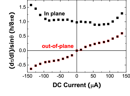
Both studies prove a quadratic bias dependence of the term as well as a second order polynomial dependence of (see Fig. 17), confirming the recent theories on spin torque in MTJtheo ; manchon ; slonc07 . Furthermore, both torques are found to be of the same order of magnitude.
The determination of the bias dependence of the out-of-plane component is very tricky since this torque only induces a small shift in the resonance peaks of the measured signals. Furthermore, the treatment of temperature issues (temperature dependence of the signal, thermal activation, Joule effects, Peltier effects and "thermal spin transfer torque"hatami ) as well as de-embedding procedure must be properly undertaken.
IV.4.2 Thermally activated phase diagrams
Very recent experiments, not yet published, have proposed to study the thermally activated phase diagrams of magnetic tunnel junctions in order to describe the spin transfer torque bias dependence. Such phase diagram shows the stable magnetic state of the free layer of a spin-valve device, as a function of both the applied field and the injected current.
A first experiment was performed by Li et al. prlli in order to get the bias dependence of torques from the bias dependence of the critical switching fields of the free layer of a MgO-based MTJ. The authors used short bias voltage pulses to increase the maximum bias voltage above the quasistatic breakdown voltage without damaging the junction. They succeeded in describing the in-plane and out-of-plane torques, claiming a linear bias dependence for the first and a mostly quadratic dependence for the second one. However, contrary to previous results, the authors give a bias dependence of the form , where is the current density flowing through the junction.
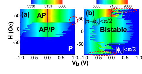
Manchon et al. manchonkj used a slightly different technique, without short pulses and succeeded to draw a complete phase diagram in two different magnetic configurations: (a) when the external field is applied along the easy axis of the free layer and (b) when the external field is applied along the hard axis of the free layer. These diagrams are given in Fig. 18, for two different samples (A and B).
Assuming, in a first approximation, that the in-plane torque is linear as a function of bias voltage, several fits of the thermally activated phase diagrams were performed, using the theory of thermal activation developed by Koch et al. koch ; Sun ; Li . Fig. 19 shows the three fits the authors obtained, assuming (black), (blue) and (red), where is a fitting parameter.
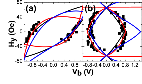
Assuming a quadratic bias dependence of the out-of-plane torque term introduces an significant asymmetry in both longitudinal and transverse stability diagrams that is not observed experimentally. Furthermore, although no significant difference appears in the transverse stability diagram when assuming = 0 or (black and red curves in Fig. 19(b)), the best fit of the longitudinal diagram is clearly obtained when is linear. This indicates that in our samples, should be an odd function of the applied bias V , contrary to Sankey et al. sankeynat and Kubota et al. kubota .
This linear bias dependence is in contradiction with the recent published theoriestheo ; manchon predicting a quadratic bias dependence of the out-of-plane torque. These theories assume amorphous tunnel barrier, low bias voltage, semi-infinite free layer thickness and zero temperature whereas we performed our measurements on MTJs comprising crystalline MgO barrier at room temperature. Consequently, the differences between our experiments and these theories may be ascribed to the crystalline nature of the MgO barrier as well as other contributions such as spin-waves emissions that have not been considered in the calculations despite their strong influence on the spin torque bias dependenceswmtj .
The difference with the recent RF measurementssankeynat ; kubota are more difficult to interpret. It may be attributed to the interplay between thermal effects and current-induced magnetization dynamics. Note that the results obtained by RF measurements strongly depend on the samples qualitysuzuki and may present a linear term.
These experiments are of great interest because of its relative simplicity. However, further experimental improvements are needed in order to increase the reproducibility and accuracy of the measurements and be able to measure both longitudinal and transverse phase diagram on the same sample without breakdown.
V From weak ferromagnetic to half-metallic tunnel junctions
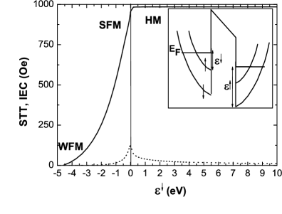
To conclude this chapter, we studied the dependence of the in-plane and out-of-plane torque as a function s-d exchange coupling , and in particular, the crossover between ferromagnetic and half-metallic tunnel junctions. As a matter of fact, as previously stated, Heiliger et al. heiliger suggested that a crystalline MgO-based tunnel junction may be approximated by a half-metallic tunnel junction, when considering the dominant contribution of symmetry.
The Fermi energy is kept constant, whereas the energy of the bottom of the minority electrons conduction band is modified, as indicated in Fig. 20. This energy is defined from the Fermi energy as:
| (58) |
where is the absolute energy of the bottom of the conduction band. When is close to , , the metallic electrodes loose their ferromagnetic nature. For , the Fermi wavevector for minority electrons becomes smaller and the current polarization is strongly enhanced. In this case, we expect an important spin transfer torque. When , becomes imaginary and the electrodes behave like a tunnel barrier for minority spins. Increasing increases the evanescent decay of minority wave functions in the electrodes. Then, the product still exists so that spin torque is non zero and decrease exponentially from the interface.
Fig. 20 shows the amplitude of in-plane and out-of-plane torques in the three different regimes: weak ferromagnetic electrodes (WFM), strong ferromagnetic electrodes (SFM) and half-metallic electrodes (HM). As expected, in ferromagnetic regime, in-plane and out-of-plane torques increase until (vertical line). When becomes positive, the bottom of the conduction band of minority electrons lies above the Fermi level: no minority electrons can propagate because only evanescent states exist near the interfaces for this spin projection. However, in-plane and out-of-plane torques do not vanish but reach a plateau which slowly decreases to zero when increasing (not shown).
To understand this behavior, we calculated the spatial dependence of the transverse spin density in the free layer. Fig. 21 shows the transverse spin density in a usual ferromagnet, eV (which corresponds to eV), as a function of the distance from the interface with the barrier in the left electrode. The oscillation possesses the same characteristics than discussed above and we observe that the transverse spin density is damped far from the interface. When decreasing , the interfacial spin density increases, due to strong spin filtering at the interface (strong spin-dependent selection), as shown on Fig. 22.
But when changes sign, only majority electrons can propagate and the transverse spin density becomes:
| (59) | |||
| (60) |
where are the barrier wave vectors at the left and right interface respectively, are the electron wave vectors in the left (right) electrode for majority and minority spins, respectively, and is a coefficient which depends on the junction parameters. Considering Fermi electrons at perpendicular incidence, very small bias voltage () and imaginary minority electron spin wave vector, , we obtain straightforwardly:
| (61) | |||
| (62) |
The transverse spin density is a product between oscillating function of and exponentially decaying function of . Fig. 23 shows the spatial evolution of the transverse spin density in the case of a half-metallic tunnel junction. All the oscillations are damped very quickly so that the only important contribution to torque comes from the interface. Contrary to usual MTJ (where both bulk averaging due to spatial interferences and interfacial spin reorientation contribute to spin torque), in a strong half-metallic tunnel junction all the torque comes from spin reorientation due to spin-dependent reflection. In this last case, the contribution of the spatial averaging between all impinging electrons (-summation) is reduced compared to interfacial spin transfer.
The interesting point is that half-metallic tunnel junctions may reproduce the general properties of MgO-based tunnel junctions. Most of the previous characteristics discussed earlier (quantum description as well as observable characteristics) are then valid in this type of junctions. This explains why simple single band per spin models, like the one proposed by Theodonis et al. theo for simple cubic crystal structure, or Manchon et al. manchon , assuming amorphous tunnel barrier, applies to experimental results obtained in crystalline MgO-based MTJ. Note however that this agreement holds for thick enough MgO barriers and that the quality of the tunnel junction should strongly affect the half-metallic characteristic. Other symmetry channels may then contribute to the transport, like resonant interfacial states for example tsymbal ; tiusan07 .
Kubota et al. kub2006 recently studied the dependence of the critical switching current density on the thickness of the free layer in a MgO-based MTJ. The authors found that the critical current density was roughly proportional to the free layer thickness. This indicates that the transverse spin current is completely absorbed within the free layer, and that consequently the spin transfer torque seems to take place close to the interface between the insulator and the ferromagnetic electrode, consistently with the above discussion.
VI Conclusion
As stated in the introduction, since its first prediction slonc89 and observation huai ; fuchs , spin transfer torque in tunnel junctions was expected to present strong differences compared to spin torques in metallic spin valves. The single-electron nature of the tunnelling transport, the specific spin-selection induced by the tunnel barrier, as well as the non linearity of the tunnelling process itself were expected to strongly affect the observable properties of spin transfer torque.
The smaller role of spin accumulation is also of great importance since the angular dependence of spin torque coefficient and are unusually small in MTJs. Another characteristic is the significant amplitude of the out-of-plane component of spin transfer torque, arising from the spin-selection occurring at the tunnel barrier.
Most interesting, recent experiments based on RF techniques or (quasi-)static measurements have revealed significant non linearities in the spin torque bias dependence, due to the non-linearity of the tunnelling transport. The most striking element is that these experiments seem to agree with tight-biding or free-electron models, i.e. models making very simplistic and restrictive assumptions on the energy dependence of the interfacial densities of states and on the barrier shape. Although it has been widely shown that MgO-based tunnel junctions possess a complex electronic band structure, these experiments are conveniently reproduced by parabolic or bell-like band structure. This surprising simplicity may be attributed, as proposed in section V, by the dominant contribution of symmetry electrons, at low bias and not-too-thin barrier width.
However, more accuracy is needed both in the theories and experiments in order to better describe these specificities. Junctions asymmetries, inelastic scattering or impurities have been shown to deeply modify the spin torque properties in MTJs. Hot-electrons spin-waves emission is also known to be of great importance in MTJs, leading to the so-called "zero-bias anomaly". This emission is also expected to significantly affect the bias dependence of spin transfer torque.
We stressed out the simplicity of the models that have been proposed up to now to describe spin torques in MTJs. Realistic band structure calculations should enrich our knowledge of spin torque origins, especially by modifying the spin-filtering mechanism and the interference process between the majority and minority electrons. The ballistic assumption, namely neglecting all spin-flip scattering, limits the investigation to academic systems. Taking spin-orbit coupling into account would be of great interest to quantitatively simulate real magnetic devices.
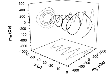
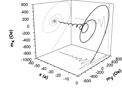
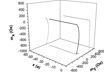
Finally, nothing have been said in this chapter about the time-domain investigations of magnetization dynamics in MTJs. Preliminary experimental studies were carried out by Devolder et al. devolder that show interesting magnetic behaviors not observed in metallic spin-valves until now.
As we tried to show in this chapter, although quite incomplete, the recent research on spin transfer in MTJs has already revealed rich and exciting issues that only wait for further theoretical and experimental efforts.
Acknowledgements.
The authors acknowledge fruitful discussions with Prof. Zhang, Prof. Kubota, T. Devolder, Prof. Miltat, M.D. Stiles. We gratefully acknowledge the support of J.-E. Lee and S.-C. Oh from Samsung Electronics Co. for providing the MgO-based samples. We also thank Prof. D.C. Ralph, G. Fuchs and S. Petit for their agreement in reproducing apart of their exciting work.Financial support by the European Commission within the EU-RTNs SPINSWITCH (MRTN-CT-2006-035327) is gratefully acknowledged. The views expressed are solely those of the authors, and the other Contractors and/or the European Community cannot be held liable for any use that may be made of the information contained herein.This work was partially supported by the Russian fund for basic research.REFERENCES
References
- (1) M. N. Baibich, J. M. Broto, A. Fert, F. Nguyen Van Dau, F. Petroff, P. Etienne, G. Creuzet, A. Friederich et J. Chazelas, Phys. Rev. Lett. 61, 2472 (1988).
- (2) G. Binasch, P. Grünberg, F. Saurenbach et W. Zinn, Phys. Rev. B 39, 4828 (1989).
- (3) L. Berger, J. Appl. Phys. 49, 2156 (1978).
- (4) B. Dieny, V. S. Speriosu, S. S. P. Parkin, B. A. Gurney, D. R. Wilhoit et D. Mauri, Phys. Rev. B 43, 1297 (1991).
- (5) J. C. Slonczewski, J. Magn. Magn. Mat. 159, L1 (1996).
- (6) L. Berger, Phys. Rev. B 54, 9353 (1996).
- (7) J. Bass and W. P. Pratt Jr, J. Magn. Magn. Mat. 200, 274 (1999).
- (8) See for example W. J. Gallagher and S. S. P. Parkin, IBM J. RES. & DEV. VOL. 50, 5 (2006) and references therein.
- (9) O. Redon, B. Dieny and B. Rodmacq, US Patent No. 6,532,164 B2 (2003);D. Houssameddine, U. Ebels, B. Delaët, B. Rodmacq, I. Firastrau, F. Ponthenier, M. Brunet, C. Thirion, J.-P. Michel, L. Prejbeanu-Buda, M.-C. Cyrille, O. Redon, B. Dieny, Nature Materials 6, 441 (2007).
- (10) J. A. Katine, F. J. Albert, R. A. Buhrman, E. B. Myers and D. C. Ralph, Phys. Rev. Lett. 84, 3149 (2000).
- (11) S. I. Kiselev, J. C. Sankey, I. N. Krivorotov, N. C. Emley, R. J. Schoelkopf, R. A. Buhrman et D. C. Ralph, Nature 425, 380 (2003)
- (12) W. H. Rippard, M. R. Pufall, S. Kaka, T. J. Silva, and S. E. Russek, Phys. Rev. B 70, 100406(R) (2004).
- (13) S. Urazhdin, N. O. Birge, W. P. Pratt and J. Bass, Appl. Phys. Lett. 84, 1516 (2004); S. Urazhdin, H. Kurt, M. AlHajDarwish, N. O. Birge, W. P. Pratt Jr and J. Bass, J. Appl. Phys. 97, 10C701 (2005).
- (14) M. AlHajDarwish, H. Kurt, S. Urazhdin, A. Fert, R. Loloee, W.P. Pratt, Jr., and J. Bass, Phys. Rev. Lett. 93, 157203 (2004); M. AlHajDarwish, A. Fert, W.P. Pratt, Jr., and J. Bass, J. Appl. Phys. 95, 6771 (2004).
- (15) M. D. Stiles and A. Zangwill, Phys. Rev. B 66, 014407 (2002).
- (16) See for example A. A. Kovalev, A. Brataas, and Gerrit E. W. Bauer, Phys. Rev. B 66, 224424 (2002);J. Barnas, A. Fert, M. Gmitra, I. Weymann, and V. K. Dugaev, Phys. Rev. B 72, 024426 (2005).
- (17) A. Manchon, N. Ryzhanova, N. Strelkov, A. Vedyayev and B. Dieny, J. Phys.: Condens. Matter 19, 165212 (2007).
- (18) M. Jullière, Phys. Lett. 54A, 225 (1975); R. Meservey and P. M. Tedrow, Phys. Rep. 238, 173 (1994).
- (19) J. S. Moodera, L. R. Kinder, T. M. Wong and R. Meservey, Phys. Rev. Lett. 74, 3273 (1995).
- (20) S. Ideka, J. Hayakawa, Y. M. Lee, F. Matsukura, Y. Ohno, T. Hanyu, IEEE Trans. Elect. Dev. 54, 991 (2007).
- (21) P. LeClair, H. J. M. Swagten, J. T. Kohlhepp, R. J. M. van de Veerdonk, and W. J. M. de Jonge Phys. Rev. Lett. 84, 2933 (2000).
- (22) M. Sharma, S.X. Wang and J.H. Nickel, Phys. Rev. Lett. 82, 616 (1999).
- (23) E.Y. Tsymbal and D.G. Pettifor, Phys. Rev. B 58, 432 (1998).
- (24) A. Vedyayev, D. Bagrets, A. Bagrets and B. Dieny, Phys. Rev. B 63, 064429 (2001); E.Y. Tsymbal, A. Sokolov, I.F. Sabirianov and B. Doudin, Phys. Rev. Lett. 90, 186602 (2003); F. Kanjouri, N. Ryzhanova, N. Strelkov, A. Vedyayev and B. Dieny, J. Appl. Phys. 98, 083901 (2005); A. Manchon, N. Ryzhanova, N. Strelkov, A. Vedyayev and B. Dieny, to be published.
- (25) E.Y. Tsymbal, O.N. Mryasov and P.R. LeClair, J. Phys.: Condens. Matter 15, R109 (2003).
- (26) Y. Huai, F. Albert, P. Nguyen, M. Pakala, and T. Valet, Appl. Phys. Lett. 84, 3118 (2004)
- (27) G. D. Fuchs, N. C. Emley, I. N. Krivorotov, P. M. Braganca, E. M. Ryan, S. I. Kiselev, J. C. Sankey, D. C. Ralph, R. A. Buhrman, and J. A. Katine, Appl. Phys. Lett. 85, 1205 (2004).
- (28) S. Ideka et al. J. J. Appl. Phys. 44, L1442 (2005).
- (29) N. Garcia, Appl. Phys. Lett. 77, 1351 (2000); D. Allen, R. Schad, G. Zangari, I. Zana, D. Yang, M. C. Tondra et D. Wang, J. Vac. Sci. Technol. A 18, 1830 (2000); D. Allen, R. Schad, G. Zangari, I. Zana, D. Yang, M. Tondra et D. Wang, J. Appl. Phys., 87, 5188 (2000); E. P. Price, D. J. Smith, R. C. Dynes et A. E. Berkowitz, Appl. Phys. Lett. 80, 285 (2002).
- (30) W. H. Butler, X. G. Zhang, T. C. Schulthess and J. M. MacLaren, Phys. Rev. B 63, 054416 (2001).
- (31) W. H. Butler, X. G. Zhang, S. Vutukuri, M. Chshiev, T. C. Schulthess, IEEE Trans. Mag. 41, 2645 (2005).
- (32) Z. Diao, D. Apalkov, M. Pakala, Y. Ding, A. Panchula et Y. Huaia, Appl. Phys. Lett. 87, 232502 (2005).
- (33) Y. Huai, M. Pakala, Z. Diao, D. Apalkov, Y. Ding et A. Panchula, J. Magn. Magn. Mater. 304, 88 (2006).
- (34) D. Belaschenko, E. Y. Tsymbal, M. van Schilfgaarde, D. A. Stewart, I. I. Oleynik et S. S. Jaswal, Phys. Rev. B 69, 174408 (2004); J. Mathon et A. Umerski, Phys. Rev. B 60 1117 (1999).
- (35) J. C. Slonczewski, Phys. Rev. B 71, 024411 (2005).
- (36) H. A. M. van den Berg, W. Clemens, G. Gieres, G. Rupp, W. Schelter and M. Vieth, IEEE Trans. Magn. 32, 4624 (1996); J. L. Leal and M. H. Kryder, J. Appl. Phys. 83, 3720 (1998).
- (37) S. Zhang, P. M. Levy, A. C. Marley et S. S. P. Parkin, Phys. Rev. Lett. 79, 3744 (1997).
- (38) B. Dieny et O. Redon, Patent 01-14840 FR2832542; B. Dieny, O. Redon et B. Rodmacq, Patent 00-15895 FR2817999.
- (39) G. D. Fuchs, I. N. Krivorotov, P. M. Braganca, N. C. Emley, A. G. F. Garcia, D. C. Ralph et R. A. Buhrman, Appl. Phys. Lett. 86, 152509 (2005).
- (40) Y. Huai, M. Pakala, Z. Diao et Y. Ding, Appl. Phys. Lett. 87, 222510 (2005).
- (41) T. Inokuchi, Y. Saito et H. Sugiyama, Patent US 2006/0227465 A1.
- (42) P. M. Levy et A. Fert, Phys. Rev. Lett. 97, 097205 (2006); P.M. Levy et A. Fert, Phys.Rev. B 74, 224446 (2006).
- (43) A. A. Tulapurkar, Y. Suzuki, A. Fukushima, H. Kubota, H. Maehara, K. Tsunekawa, D. D. Djayaprawira, N. Watanabe et S. Yuasa, Nature 438, 339 (2005).
- (44) H. Kubota, A. Fukushima, K. Yakushiji, T. Nagahama, S. Yuasa, K. Ando, H. Maehara, Y. Nagamine, K. Tsunekawa, D. D. Djayaprawira, N. Watanabe, and Y. Suzuki, Nature Physics 4, 37 (2008).
- (45) J. C. Sankey, P. M. Braganca, A. G. F. Garcia, I. N. Krivorotov, R. A. Buhrman et D. C. Ralph, Phys. Rev. Lett. 96, 227601 (2006).
- (46) J. C. Sankey, Y.-T. Cui, R. A. Buhrman, D. C. Ralph, J. Z. Sun, and J. C. Slonczewski, Nature Physics 4, 37 (2008).
- (47) A. V. Nazarov, H. M. Olson, H. Cho, K. Nikolaev, Z. Gao, S. Stokes et B. B. Pant, Appl. Phys. Lett. 88, 162504 (2006)
- (48) J.-G. Zhu, Y. Zhou et S. Mao, IEEE Trans. Magn. 42, 2441 (2006).
- (49) S. Petit, C. Baraduc, C. Thirion, U. Ebels, Y. Liu, M. Li, P. Wang et B. Dieny, Phys. Rev. Lett. 98, 077203 (2007).
- (50) M. Johnson et R. H. Silsbee, Phys. Rev. Lett. 55, 1790 (1985); M. Johnson et R. H. Silsbee, Phys. Rev. B 35, 4959 (1987); M. Johnson, Phys. Rev. Lett. 70, 2142 (1993).
- (51) P. C. van Son, H. van Kempen et P. Wyder, Phys. Rev. Lett. 58, 2271 (1987).
- (52) S. Urazhdin, R. Loloee, and W. P. Pratt Jr., Phys. Rev. B 71, 100401(R) (2005).
- (53) J. C. Slonczewski, Phys. Rev. B 39, 6995 (1989).
- (54) J. C. Slonczewski, J. Magn. Magn. Mat. 247, 324 (2002).
- (55) L. Berger, J. Appl. Phys. 89, 5521 (2001).
- (56) A. Fert, V. Cros, J.-M. George, J. Grollier, H. Jaffrès, A. Hamzic, A. Vaurès, G. Faini, J. Ben Youssef et H. Le Gall, J. Magn. Magn. Mater. 272, 1706 (2004).
- (57) D. M. Edwards, F. Federici, J. Mathon, and A. Umerski, Phys. Rev. B 71, 054407 (2005).
- (58) S. Zhang, P. M. Levy et A. Fert, Phys. Rev. Lett. 88, 236601 (2002).
- (59) M. B. Stearns, Phys. Rev. B 8, 4383 (1973).
- (60) S. Zhang and Z. Li, Phys. Rev. Lett. 93, 127204 (2004).
- (61) J. Miltat, G. Albuquerque, and A. Thiaville, "An Introduction to Micromagnetics in the Dynamic Regime", in Spin Dynamics in Confined Magnetic Structures I, B. Hillebrands and K. Ounadjela (Eds.), Topics in Applied Physics 83 (Springer-Verlag, 2002).
- (62) J.C. Slonczewski et J.Z. Sun, J. Magn. Magn. Mater. 310, 169-175 (2007).
- (63) K. D. Belaschenko, E. Y. Tsymbal, M. van Schilfgaarde, D. A. Stewart, I. I. Oleinik, and S. S. Jaswal, Phys. Rev. B 69, 174408 (2004).
- (64) J. Mathon et A. Umerski, Phys. Rev. B 60 1117 (1999).
- (65) I. Theodonis, N. Kioussis, A. Kalitsov, M. Chshiev, and W. H. Butler, Phys.Rev. Lett. 97, 237205 (2006).
- (66) A. Kalitsov, I. Theodonis, N. Kioussis, M. Chshiev, W. H. Butler and A. Vedyayev, J. Appl. Phys. 99, 08G501 (2006).
- (67) M. Wilczynski, J. Barnas et R. Swirkowicz, unpublished
- (68) A. Manchon, N. Ryzhanova, A. Vedyayev and B. Dieny, arXivarXiv:0712.0055 (2007).
- (69) Z. Li, S. Zhang, Y. Ding, Z. Diao, D. Apalkov, Z. Yang, K. Kawabata, and Y. Huai, unpublished
- (70) C. Heiliger and M. D. Stiles, unpublished
- (71) E. Y. Tsymbal, K. D. Belaschenko, J. P. Velev, S. S. Jaswal, M. van Schilfgaarde, I. I. Oleynik and D. A. Stewart, Prog. Mat. Sc. 52, 401 (2007).
- (72) S. Datta, Electronic Transport in Mesoscopic Systems, Cambridge Studies in Semiconductor Physics Series (1995).
- (73) L. V. Keldysh, Soviet Physics JETP 20, 1018 (1965).
- (74) A. M. Bratkovsky, Phys. Rev B 56, 2344 (1997).
- (75) J. Faure-Vincent, C. Tiusan, C. Bellouard, E. Popova, M. Hehn, F. Montaigne, and A. Schuhl, Phys. Rev. Lett. 89, 107206 (2002).
- (76) C. Tiusan, F. Greullet, M. Hehn, F. Montaigne, S. Andrieu and A. Schuhl, J. Phys.: Condens. Matter 19, 165201 (2007).
- (77) C. Tiusan, J. Faure-Vincent, C. Bellouard, M. Hehn, E. Jouguelet, and A. Schuhl Phys. Rev. Lett. 93, 106602 (2004); F. Greullet, C. Tiusan, F. Montaigne, M. Hehn, D. Halley, O. Bengone, M. Bowen, and W. Weber, Phys. Rev. Lett. 99, 187202 (2007).
- (78) R. Elliott, Phys. Rev. 96, 266 (1954).
- (79) Y. Yafet, Solid State Physics (Academic, New York, 1963), Vol. 14; Y. Yafet, J. Appl. Phys. 42, 1564 (1971).
- (80) A. Fert, J. Phys. C 2, 1784 (1969).
- (81) J. Bass and J. W. Pratt Jr., J. Phys.: Condens. Matter 19, 183201 (2007).
- (82) M. Zwierzycki, Y. Tserkovnyak, P. J. Kelly, A. Brataas, and G. E. W. Bauer, Phys. Rev. B 71, 064420 (2005).
- (83) M. Elsen, O. Boulle, J.-M. George, H. Jaffr¨¨s, R. Mattana, V. Cros, A. Fert, A. Lemaitre, R. Giraud, and G. Faini Phys. Rev. B 73, 035303 (2006).
- (84) W. F. Brinkman, R. C. Dynes et J. M. Rowell, J. Appl. Phys. 41, 1915 (1970).
- (85) G. D. Fuchs, J. A. Katine, S. I. Kiselev, D. Mauri, K. S. Wooley, D. C. Ralph, and R. A. Buhrman, Phys. Rev. Lett. 96, 186603 (2006).
- (86) M. Hatami, G. E.W. Bauer, Q. Zhang and P. J. Kelly, Phys. Rev. Lett. 99, 066603 (2007).
- (87) A. Manchon, B. Dieny, K.-J. Lee, unpublished
- (88) R. H. Koch, J. A. Katine and J. Z. Sun, Phys. Rev. Lett. 92, 088302 (2004).
- (89) J. Z. Sun, Phys. Rev. B 62, 570 (2000).
- (90) Z. Li and S. Zhang, Phys. Rev. B 69, 134416 (2004).
- (91) Y. Suzuki and H. Kubota, private communication (2007).
- (92) H. Kubota, A. Fukushima, Y. Ootani, S. Yuasa, K. Ando, H. Maehara, K. Tsunekawa, D. D. Djayaprawira, N. Watanabe, and Y. Suzuki, Appl. Phys. Lett. 89, 032505 (2006).
- (93) T. Devolder, private communication (2007).