Address as of March 2008: ]Department of Physics & Astronomy, Johns Hopkins University, Baltimore, MD 21218
Two-dimensional vortex behavior in highly underdoped YBa2Cu3O6+x observed by scanning Hall probe microscopy
Abstract
We report scanning Hall probe microscopy of highly underdoped superconducting YBa2Cu3O6+x with ranging from 5 to 15 K which showed distinct flux bundles with less than one superconducting flux quantum () through the sample surface. The sub- features occurred more frequently for lower , were more mobile than conventional vortices, and occurred more readily when the sample was cooled with an in-plane field component. We show that these features are consistent with kinked stacks of pancake vortices.
pacs:
74.25.Ha, 74.25.Qt, 74.72.BkI Introduction
Cuprate superconductivity occurs mainly in the direction on the planes. This quasi-two-dimensional nature manifests itself in the anisotropy between the -axis penetration depth () and the in-plane penetration depth (). ClemClem (1991) showed that in highly anisotropic layered superconductors a -axis vortex can be viewed as a stack of magnetically coupled “pancake” vortices, one in each layer. This formulation suggested the possibility for novel vortex behavior and has become a major part of the phenomenological understanding of cuprate superconductors. However, direct observations of separated pancakes or pancake stacks have been rare.Grigorenko et al. (2002); Beleggia et al. (2004)
In this paper, we present scanned probe microscopy of magnetic flux in highly underdoped YBa2Cu3O6+x (YBCO) single crystals. We observed nearly isolated flux features with less than one flux quantum ( G m2) through the sample surface, which we call “partial vortices”. A model of separated pancake vortex stacks, similar to a kinked structure suggested by Benkraouda and Clem,Benkraouda and Clem (1996) but with a more important role for pinning, agrees well with our observations.
Non-quantized flux in superconductors has been observed experimentally, arising for different reasons. Geim et al.Geim et al. (2000) observed non-quantized flux penetration in mesoscopic thin film samples of aluminum due to two effects: the proximity of the vortices to the sample edge, and a surface barrier to flux penetration. Sub- flux has been imaged in YBCO thin films along grain boundaries separating regions of the crystal rotated 45∘ about the -axis due to the -wave symmetry of the pairing state in combination with facets along the grain boundary.Kirtley et al. (1995); Mannhart et al. (1996) For our measurements discussed here, the vortices were far from the edge and there were no rotations of the crystal axes aside from 90∘ twinning, so neither of these mechanisms applies. Our observations of seemingly isolated fractional fluxes in a bulk material far from any boundaries requires a different explanation.
This paper is organized as follows. Section II describes the growth and preparation of the high-quality highly underdoped YBCO crystals and introduces the scanning Hall probe microscope. Section III discusses Hall probe observations of partial vortices, and in Sec. IV we model these partial vortices as kinked stacks of two-dimensional (2D) pancake vortices. Section V presents other experimentally observed properties, which are all consistent with the kinked vortex picture. Finally, in Sec. VI we discuss the partial vortices in light of energy costs and pinning. The Appendix of this paper discusses the in-plane penetration depth extracted from fits to vortices in the YBCO.
II Samples and methods
The YBa2Cu3O6+x crystals, with from 0.34 to 0.375, are grown with a self-flux method in BaZrO3 crucibles detailed elsewhere.Liang et al. (1998, 2002) After growth, the desired oxygen content is set during a 900–930 anneal in flowing oxygen, then oxygen inhomogeneities are removed during a 1–2 week 570 anneal in a small tube with YBCO ceramic at the same oxygen content. Initially, after quenching to 0, the crystals are non-superconducting, but annealing at room temperature allows the oxygen atoms to order into Ortho-II (every other chain empty) chain fragments whose increasing length provides the carrier doping in the CuO2 planes.Liang et al. (2002) The superconducting transition temperature () increases with room temperature annealing until saturation is reached after several weeks, giving final values of 5–20 K with bulk susceptibility transition widths (10%–90%) of less than 2 K.Liang et al. (2002) This early generation of underdoped samples sometimes had a small (2%) volume fraction of the 50–60 K phase of Ortho-II YBCO, as observed in magnetization measurements.Liang During the room temperature annealing, a single crystal can be observed at a range of values. The platelet shaped crystals are about wide, with their surface parallel to the -plane, and are typically 10–100 m thick. As grown, the crystals have twinning boundaries, but they can be detwinned under uniaxial pressure at elevated temperatures.
Our most detailed observations of sub- partial vortices were made with a scanning Hall probe microscope,Guikema (2004); Chang et al. (1992); Davidović et al. (1996); Oral et al. (1996) described in Ref. Guikema, 2004. Scanning Hall probe microscopy of single vortices is an established techniqueChang et al. (1992); Davidović et al. (1996); Oral et al. (1996) first demonstrated by A. M. Chang et al.Chang et al. (1992) Our Hall probe was made from GaAs/AlGaAs two-dimensional electron gas and had lithographic size . The Hall probe measures the perpendicular magnetic field in the active area (with a constant offset). The Hall cross was covered by a thin film of gold which was grounded during operation. This gate prevented any stray electric charges on the sample surface from perturbing the Hall signal. For positioning in the direction, the probe is mounted on the end of a thin aluminum diving board which forms a parallel plate capacitor with a copper pad underneath it. As the tip of the probe approaches the sample, we monitor the capacitance and can ideally determine the location of the sample surface to within 10 nm. This touchdown procedure is repeated at multiple locations within the scan area and then the probe is scanned in a plane just above the sample surface. The minimum height of the Hall cross active area above the sample surface is determined by the sample-probe alignment and for these measurements was 0.4 m or larger due to geometric constraints. The lateral scan range of the microscope at 4 K is 60 m and the sample can also be repositioned using stick-slip course motion. For improved signal-to-noise ratio, we averaged multiple images (having checked that the consecutive images did not show changes). We sometimes used an scanning superconducting quantum interference device (SQUID) with better flux sensitivity, but worse spatial resolution than the Hall probe. The cryostat was inside triple-layer mu-metal magnetic shielding with a residual field of less than 25 mG.
The main results presented in this paper are from an 8 m thick twinned YBa2Cu3O6.375 crystal imaged at eight stages during the room temperature oxygen ordering annealing. The annealing took place in the microscope in a helium atmosphere. After 36 hours of annealing, the crystal had K and transition width K. Further annealing gave a range of values all having K. The maximum measured was 14.7 K (Fig. 1 inset).
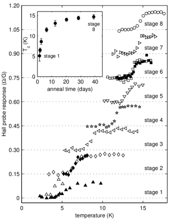
values were obtained in situ in an 8.3 mHz applied field of amplitude 0.20–0.25 Oe (Fig. 1). The transitions are described as midpoint ’s with full widths limited by the 10% resolution of the susceptibility measurement.
We also imaged flux in nine other similarly prepared YBa2Cu3O6+x crystals with in the range 0.35–0.375 and ’s in the range 7–17 K. Each of these crystals was studied at only one value. Sub- flux features were seen in the three crystals with the lowest K values.Guikema (2004) The higher samples with K only showed flux consistent with conventional vortices. We also imaged vortices in Ortho-II ( K) and near-optimally doped YBCO crystals and did not see any evidence of sub- partial vortices.
III Flux images
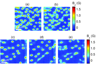
We saw over 100 sub- flux features in the YBa2Cu3O6.375 crystal while tuning from 5 to 15 K. We also observed more than 300 apparently full vortices, which were dominant for K. Typical Hall probe images are shown in Fig. 2 for a range of .
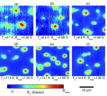
These images were taken at low temperatures () after field-cooling the crystal at about 3 K/min in a perpendicular field. Though not necessary, the images were taken after turning off the applied field at low temperature. Images taken before and after turning off the field looked identical. No flux features were observed when we cooled the sample in zero field. The images were not all taken at the same place on the crystal, because we occasionally used our course motion capability to move the sample in order to view nearby regions.
The images in Fig. 2 show flux features that can be divided into two types. We identify the brightest features, which are close to circular, as conventional or “full” vortices. They carry total flux through the crystal surface, within experimental error. The full vortices increased in peak and decreased in width as increased, likely due to changes in the in-plane penetration depth (see Appendix). Other features have a smaller peak and appear either circular, elongated, or with tails. We call these features “partial vortices” because they carry less than of total flux through the surface. When the sample was cooled in a perpendicular field, partial vortices accounted for more than half of the observed flux features for K (stages 1–4), but dropped to less than 10% for K (stages 7 and 8).Guikema (2004) We will show that the partial vortices can be explained by non-axial arrangements of 2D pancake vortices.
The flux carried by the partial vortices was not restricted to discrete fractions of , as shown by a tally of the ratios of the peak of a partial vortex to the peak of a full vortex in the same image (Fig. 3).
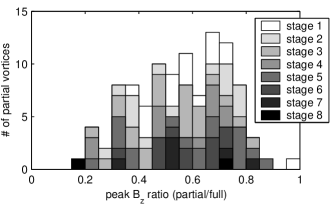
The peak ratio for a partial vortex does not translate directly to the fraction of a through the surface, but nonetheless, Fig. 3 indicates that the partial vortices occurred for a range of magnitudes. It is not feasible to directly tally the flux of each partial vortex without large errors because the field from nearby vortices in many cases interferes with the integration.
A tempting hypothesis is that a partial vortex consists of a straight stack of pancake vortices, one in each layer, with some unusual mechanism by which the total flux is permitted to be less than . In this case, the field profile of a partial vortex above the sample surface could be calculated using the anisotropic London model (see Eq. (5) in the Appendix) except with a flux smaller than . If the in-plane penetration depth was assumed to be constant throughout the sample at each , then the peak ratio given in Fig. 3 would be equivalent to the fraction of a flux quantum carried by the partial vortex. However, we do not believe this hypothesis is the best explanation of our data.
The main sources of error in the peak ratios were noise in the data and error in background determination, roughly 50 mG each. This gives an error in the peak ratios of 5% at the higher values, and several times this for the lowest . Counts may also be missing at the ends of the histogram, since a partial vortex with close to full peak would likely be mistaken as a full vortex and those with very small peak field may have been lost in the noise. We omitted some flux features from the histogram if they could not be clearly identified as partial or full vortices. We also omitted whole images if they had high noise or did not contain a full vortex, the latter being particularly an issue for the lowest anneal stage where full vortices were rare. Only 21% of the images from stage 1 were included in the tally, while most images from subsequent stages were included.
IV Kinked pancake stacks
In this section we discuss a model in which the partial vortices result from kinked stacks of pancake vortices. We show that the model quantitatively describes the most circular partial vortices, and qualitatively describes the shapes and tails of the non-circular ones.
In Ref. Clem, 1991, Clem introduced the idea of 2D pancake vortices as the basic building blocks of 3D vortices in highly anisotropic superconductors consisting of weakly Josephson coupled layers. Even when the interlayer Josephson coupling is not negligible, the vortex structure can be described as a superposition of 2D pancake vortices and short sections of Josephson vortices (called “strings”) connecting pancakes in adjacent layers.Clem (2004) ClemClem (1991) also showed that for a vortex aligned along the -axis, a straight stack of 2D pancake vortices gives the same result as an ordinary 3D vortex in the anisotropic London model. However, Benkraouda and ClemBenkraouda and Clem (1996) proposed that a tilted pancake stack may lower its energy by instead forming a kinked structure similar to the one shown in Fig. 4(c), rather than maintaining a homogeneous tilt angle. Our observations of partial vortices suggest such configurations of kinks and short pancake stacks, which are stabilized by pinning effects.
Compared to optimally doped YBCO, where ,Dolan et al. (1989) our highly underdoped YBa2Cu3O6+x (–0.375) crystals are much more anisotropic. Microwave measurements in similar samples found zero temperature values for K, and for K.Hosseini et al. (2004) The zero temperature in-plane penetration depth can be obtained from recent measurementsLiang et al. (2005) of in similar crystals which found that the power law (Oe) fit vs. data well for K. Using and (Ref. Gray et al., 1992) gives m and 0.47 m for K and 15 K, respectively. These values are in agreement with values we obtained from fits to Hall probe vortex images from our variable YBa2Cu3O6.375 crystal as discussed in the Appendix. Thus for K and for K in these crystals.
Since the 2D single layer screening length mm is greater than in our highly underdoped YBCO crystals (the bilayer spacing in YBCO is nm), interlayer Josephson coupling is not negligibleClem (1991) and the notion of purely magnetically coupled pancakes is not entirely accurate. However, due to the large values of and , the additional attraction between separated pancake stacks due to Josephson strings is smaller than the magnetic interaction, as will be discussed in Sec. VI. Thus the pancake vortex plus Josephson string picture should be at least qualitatively appropriate for these samples.
To show that short pancake stacks can explain our observations, we consider the magnetic field that a straight partial stack extending from to () generates above the surface of a layered superconductor assumed to be much thicker than . It was shown in Ref. Clem, 2004 that the component of the magnetic field at a height above the surface and a radius from the vortex axis is
| (1) |
where and the layer spacing is much smaller than both and . If the partial stack extends from to , Eq. (1) gives the field of a conventional 3D vortex (Eq. (5)). Integrating Eq. (1) gives total flux
| (2) |
through the surface of a superconducting half space for a partial vortex extending from to .Clem (1994, 2004) If an otherwise straight vortex stack has one kink at a depth , the total flux through the surface from the lower and upper partial stacks is and , respectively. The total flux is , as expected.
To compare the kinked stack model with our observations, we fit the two partial vortices labeled in Fig. 4(a) to a model of a pancake stack with one kink.
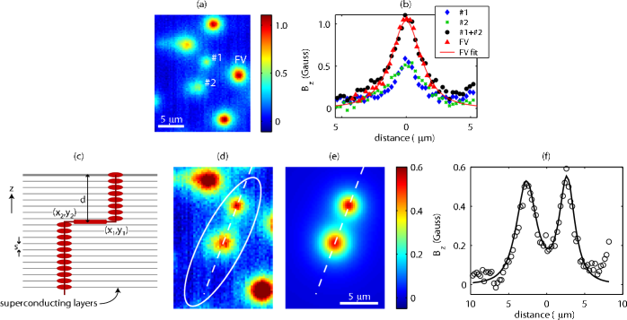
Figure 4(b) shows that partial vortex #1 has a narrower profile, so we chose it as the upper stack. Adding the field profiles (Eq. (1)) of all the partial stacks in a kinked stack gives the field profile of a straight stack (full vortex). Figure 4(b) shows that the cross section through a full vortex is similar to the sum of the cross sections through partial vortices #1 and #2.
Using non-linear regression, we fit the portion of the image shown in Fig. 4(d) inside the oval to a numerical approximation of Eq. (1) with one expression each for the lower ( to ) and upper ( to 0) partial pancake stacks. Free fit parameters were the depth of the split, , and the radial centers () and () of each partial stack (Fig. 4(c)). Fixed input values were and . This was obtained from a 2D fit to the full vortex labeled ‘FV’ in Fig. 4(a) by the method described in the Appendix. Our fit gives a depth of the kink and lateral displacement at the kink (kink length) . Figure 4(e) shows a 2D color plot of the fit and (f) shows cross-sections of the data and fit images along the dotted lines. Kinked or separated pancake vortex stacks is a plausible interpretation of our observations since, as Fig. 4 shows, the model fits well to our data.
This partial vortex pair was ideal for fitting because there appeared to be only a single kink within a few of the surface and the partial stacks were well defined and circular. In most of our partial vortex images there were multiple kinks in a stack or several intermingled kinked stacks. In these cases, fitting the data would be more complicated. It was also common for partial vortices to have non-uniform shapes (see Fig. 2) which do not strictly agree with the model of one or a few kinks in a pancake stack. Elongated partial vortices and those with apparent tails, such as the partial vortex to the upper left of #1 in Fig. 4(a), could be the result of many closely spaced kinks, a tilt of a partial stack, or even a non-uniform staggering of pancakes from layer to layer. In each of these scenarios the displacement between adjacent pancakes would be smaller than the Hall probe spatial resolution. Though the kinked stack model cannot be used to fit irregularly shaped partial vortices without many free parameters, the underlying phenomenon is similar, with 2D pancake vortices playing a critical role.
V Other characteristics
A number of observed properties of these partial vortices further substantiate the partial pancake stack interpretation as well as give further insight into their stability and pinning. Partial vortices occurred in groups, preferred certain regions in the crystal, were more mobile than full vortices, and were more likely to be formed by cooling in a tilted field.
The observed grouping of partial vortices is necessary for a kinked pancake stack, since all pancake vortices near the crystal surface carry flux through the surface which collectively adds to . We observed partial vortices up to tens-of-microns away from others in a group, so even if a partial vortex appeared isolated, other segments may have been outside the image area. One caveat would be if there were subsurface vortex termination, which could occur for small sample size.Mints et al. (2000)
Partial vortices showed a tendency to prefer certain regions of the crystal, even after a room temperature annealing. This was especially noticeable for the later anneal stages (higher ) for which partial vortices were rare. This may indicate that kinks occurred preferentially in regions of the sample which were different from the bulk, perhaps with higher disorder, more pinning sites, or weaker superconductivity. At the lowest stage, we observed that partial vortices were more likely to pin where the tip of the Hall probe sat when the probe’s active area was centered over the scan area. This was the location of the probe during cooldown through and also the place where the approach was most often performed to determine the location of the sample. The vortices may have been preferentially attracted to the location of the probe’s tip, or the repeated contact with the sample in that location could have created pinning sites.
We also found that partial vortices were more mobile than apparent full vortices in the same samples. For example, partial vortices sometimes moved or coalesced after stick-slip coarse motion of the sample holder in the or directions. This was not observed for full vortices. Figure 5 shows Hall probe images before and after several ramps of the voltage on the piezoelectric and slight coarse motion.
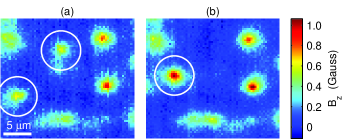
Two partial vortices of similar peak amplitude in Fig. 5(a) appeared to coalesce into one full vortex in Fig. 5(b). Motion of partial vortices during coarse motion could be due to stray fields from the stick-slip high voltage pulses, which might create forces large enough to unpin some partial vortices. Once unpinned, a kinked stack could realign to a straight stack as favored by electromagnetic coupling of the pancakes and by any Josephson coupling.
To encourage partial vortex formation, we cooled the sample in a magnetic field with a horizontal component to reduce the energy cost of a kink. With the YBa2Cu3O6.375 crystal almost fully annealed with K (stage 7), the sample was cooled through in an applied field . The vortex arrangement did not change when the field was turned off at 4 K. The images in Fig. 6 show increased numbers of partial vortices with increased .
The magnitude of determined the density of flux observed in the images. The horizontal field may have caused pancakes within a stack to pin at large displacements with respect to each other as was lowered through . Since the flux arrangement did not change when the field was turned off, the pinning must have been sufficiently strong to overcome the restoring forces favoring a straight stack.
After cooling in a tilted field, we observed a change in the flux arrangement after the temperature was raised but still kept below . As shown in Fig. 7(a), the YBa2Cu3O6.375 sample with K (stage 7) was cooled to 3 K in a field Oe, where was chosen to induce partial vortices. While at 3 K, the applied field was turned off and no change was observed. Then the sample was warmed to K, cooled back to 3 K, and imaged again. This cycle was repeated several times with successively higher maximum . After all cycles, the flux arrangement changed.
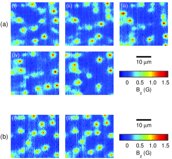
Vortices created by cooling through in Oe did not show any motion after similar thermal cycling (Fig. 7(b)). These observations indicate high metastability of the vortices for cooling in non-zero , as there are many possible structures consisting of pancake vortices and Josephson vortices in layered superconductors when cooled in a tilted field.
VI Discussion
The high-quality fit of the kinked stack model to our measured field profiles (Sec. IV), as well as the other observed properties of the sub- features (Sec. V), suggest that we have observed kinked pancake vortex stacks in the highly underdoped YBa2Cu3O6+x crystals. The large anisotropy and large in these crystals suggest that it is reasonable to think of vortices as being composed of 2D pancake vortices. Strictly speaking, however, the Josephson coupling in these crystals is not negligible compared to the magnetic coupling because is not much larger than .Clem (1991) The presence of Josephson coupling will lead to some distortion of the field profiles and to additional interaction energy, though a fully formed Josephson vortex will not exist along the kink since the kink length is typically less than . Despite non-negligible Josephson coupling, the concept of pancake vortices is still qualitatively valid here and, as we have shown in Sec. IV, gives a good quantitative approximation of the field profiles measured with the Hall probe.
Pinning is essential to explain our observations. We know that there are pinning sites in the YBCO crystals for all doping values, as is typical of type II superconductors, because vortices remain in the sample after the field is turned off below . In the absence of a field component in the -plane, magnetic coupling of the pancake vortices and any interlayer Josephson coupling favors alignment of the pancakes along the -axis. That we observe kinked pancake stacks in the highly underdoped YBCO even after the applied field is turned off indicates that pinning of the pancakes dominates the pancake vortex arrangement. It should be noted that the calculations in Sec. IV are for kinks in otherwise straight pancake vortex stacks, but pinning may cause fluctuations in the pancake positions within a stack, distorting the field profiles.Grigorenko et al. (2000)
To roughly quantify the strength of pinning required, we calculate the restoring force on the kinked structure. From Ref. Benkraouda and Clem, 1996, the energy required to deform a straight stack to a singly-kinked structure (in the limit of zero Josephson coupling and small layer spacing ) is
| (3) | |||||
where is the exponential-integral function and is Euler’s constant. The restoring force on the kinked structure with kink length found from is
| (4) |
For a kinked stack like that in Fig. 4 with model parameters and , this restoring force is 80 fN. This result is for a kink deep in a crystal.
We can also consider the additional cost of a kinked stack due to finite Josephson coupling. In the limit , which is the case for all the kinked stacks we observed, Ref. Clem, 2004 gives the energy cost of a long Josephson string connecting the two partial stacks to be of the order . The corresponding restoring force is of the order . The and values obtained from Refs. Hosseini et al., 2004 and Liang et al., 2005 give this force to be approximately 3 fN for K and 14 fN for K. Comparing this to above, the added restoring force due to the Josephson string is somewhat smaller than that of the magnetic coupling. For a longer Josephson string, the energy cost of the string increases linearly with the length and the restoring force remains constant. Thus, when the pinning force is large enough to compensate the restoring forces, there would be no theoretical limit to the maximum length of a metastable configuration. As a point of comparison with regards to pinning, measurements on a similar YBCO crystal with K have estimated the required force to unpin a full vortex to be 0.5 pN.Gardner et al. (2002)
The calculated restoring forces would be much larger for a kinked stack in optimally doped YBCO. Using the values of m (Ref. Basov et al., 1995) and (Ref. Dolan et al., 1989) for near-optimally doped YBCO, has a maximum magnitude of 3 pN when , or if as it was for the highly underdoped calculations above, would be 1 pN. In the limit of a long Josephson string, the Josephson coupling gives an additional restoring force of magnitude pN. These forces are much larger than for our highly underdoped YBCO, which is not surprising since optimally doped YBCO has much smaller anisotropy and much smaller , thus we expect the vortex behavior at higher doping to be less two-dimensional. Indeed, we have never seen partial vortices in Ortho-II ( K) or near-optimally doped YBCO crystals. Most of our measurements on these higher samples were after cooling in a perpendicular field.
Pinning in these highly underdoped crystals must be strong enough to overcome the restoring force on the kinked pancake vortex stack. The origin of the pinning sites cannot be determined from our Hall probe images. They could be regions of oxygen inhomogeneity, twinning boundaries, lattice imperfections, or something else. Future studies of the pinning landscape in these crystals and in other cuprates is desirable. It is also not known how many of the pancake vortices must be pinned to support the kinked structure in the absence of an applied parallel field. However, the total force due to pinning must be of order 80 fN to compensate for the restoring force . The data show that the pinning becomes less sufficient for kinked vortex formation for the later anneal stages (higher ). As increases during the room temperature annealing, decreases and so the restoring force increases. Also as the crystal anneals the oxygen chain fragments get longer, and this may have an effect on the pinning. However, since the crystals have Ortho-II ordering, there will still be many oxygen vacancies even when fully annealed. The number, spatial extent, and spatial distribution of vacancy clusters may all be changing at once during an anneal. An open question is whether oxygen inhomogeneities are necessary to see partial vortices in these samples.
The behavior of the vortices when cooled in a magnetic field with a parallel component (Figs. 6 and 7) also bears discussion. In a perpendicular field in the absence of pinning, a vortex should align parallel to the -axis. When the field is tilted from the perpendicular, the ground state for a vortex depends on the parameters of the sample (see for example Ref. Koshelev, 2005 for vortex lattices). In our YBCO sample and theory predicts a transition from a tilted to a parallel vortex lattice as the field approaches the -plane.Bulaevskii et al. (1992) However, Benkraouda and Clem showed that beyond small angles a kinked structure can be energetically preferable to an isolated tilted vortex, which itself is unstable beyond a tilt of .Benkraouda and Clem (1996) When our sample was cooled through in a tilted field we saw many more partial vortices, which we have suggested are kinked pancake vortex stacks. Since we did not see any changes in our images when the field was turned off at low temperature, pinning must have been sufficient to sustain the pancake vortex arrangement. However, when the sample was cycled to higher temperatures (still below ) the flux arrangement changed as shown in Fig. 7(a). We hypothesize that at the higher temperatures the pancake vortices moved in an attempt to align along the -axis, but in some cases became pinned again as kinked stacks upon cooling. In contrast, when the sample was cooled in a perpendicular field as in Fig. 7(b), the vortices were already pinned in their most stable state so no rearrangement occurred when cycled to higher temperature.
The fact that the partial vortices formed even when the sample was cooled in a perpendicular applied field along the -axis (within 1∘), especially for the lower values, further indicates the importance of pinning. Many of the sub- features are elongated or show tails, which could be due to staggering of adjacent pancakes or many unresolvable kinks, indicating a complex pinning landscape. Recent improvements in the growth and preparation of these highly underdoped YBCO crystals have resulted in better homogeneity and thus perhaps less pinning compared to the earlier generation samples studied here. An ideal sample to study would be a YBa2Cu3O6.333 crystal with Ortho-III inverse ordering (every third chain full). Such a highly underdoped crystal would have very few chain vacancies. Future work imaging flux in the next generation samples is desirable.
A few other researchers have reported observations of kinked pancake vortex stacks. Grigorenko et al.Grigorenko et al. (2002) reported a Hall probe image of one “split” pancake vortex stack in a Bi2Sr2CaCu2O8+δ (BSCCO) crystal with K. The kinked stack in that case was formed under a rapid change in magnetic field. Extensive vortex imaging has been done on BSCCOGrigorenko et al. (2001, 2002); Bending and Dodgson (2005) and typically kinked stacks such as ours have not been seen, instead combined or crossing latticesBulaevskii et al. (1992); Koshelev (1999) of pancake vortex stacks and interlayer Josephson vortices are observed. Unlike in BSCCO, we would not expect a crossing lattice to appear as the applied field approaches the -plane in our highly underdoped YBCO crystals because the Josephson length is smaller than .Bulaevskii et al. (1992)
Beleggia et al.Beleggia et al. (2004) observed dumbbell-like features consistent with kinked vortices in transmission electron microscopy images of 300–400 nm thick films of optimally doped YBCO when the applied field was within of parallel to the film. Our work suggests that kinked vortices may form more readily at low doping and can form even in the absence of an applied parallel field. The partial vortices we observed after cooling in only a perpendicular field could not have formed if sufficient pinning was not present. However, it is not known if pinning is always required to form kinked stacks when a sample is in a continuously applied tilted field.
In conclusion, we have observed sub- flux features in highly underdoped crystals of YBa2Cu3O6+x with ranging from 5 to 15 K. These “partial vortices” are well described as segments of kinked stacks of 2D pancake vortices. The partial vortices were more mobile than unkinked full vortices, formed more readily when cooled in a magnetic field with a horizontal component, and were seen most frequently for very low . Our observations provide a view of vortex behavior in the highly underdoped region of the YBCO phase diagram, showing that 2D vortex behavior and an appropriate pinning landscape can produce complex flux features at the crystal surface that are distinct from conventional vortices.
Acknowledgements.
We thank J.R. Clem, J.R. Kirtley, S.A. Kivelson, and V.G. Kogan for helpful discussions. Work at Stanford was funded by NSF Award No. 9875193 and the DoE contract DE-AC02-76SF00515. Work at UBC was funded by the CIAR and NSERC.*
Appendix A Penetration depth
We also used Hall probe images of vortices in the variable YBa2Cu3O6.375 crystal to estimate the in-plane penetration depth , which relates to the superfluid density , as a function of and . Our estimates deviate from the well established linearity between and first suggested by Uemura et al.Uemura et al. (1989, 1991) for higher doped cuprates. Our results supplement values obtained from measurements in Ref. Liang et al., 2005. The unknown height of the Hall probe above the sample gives large error bars on our results, and certain caveats discussed below lead us to conservatively interpret our results as upper bounds on .
We chose a total of 40 different vortices in the YBa2Cu3O6.375 sample for fitting, all of which appeared to be well-isolated full vortices. Each vortex was fit with the anisotropic London model in the thick crystal limit with the -plane parallel to the surface: Pearl (1966); Kogan et al. (1993); Kirtley et al. (1999a, b)
| (5) |
where , is the radial distance from the vortex axis, and is the height above the sample surface. We integrated Eq. (5) at constant over a m diameter circular area representing the Hall probe. The results are insensitive to the exact probe size and shape. We fit the vortex images using non-linear regression to extract with fixed . Free parameters were the location of the vortex center, a constant offset in the magnetic field (due to the Hall probe), and . The lengths and are strongly correlated and could not both be free parameters.
In the scanning microscope , where is the sample-probe distance when touching, and is controllable and for these measurements ranged from 0–0.16 m. Geometric constraints give a lower bound of . A very conservative upper bound of was obtained for this data set by fitting vortices at maximum with and as a free parameter. A smaller upper bound of was obtained by assuming is at least as large as in optimally doped YBCO.Basov et al. (1995) All vortices were fit with a range of values. Fit results are reported here with the typical value , with systematic error bars determined by fits with and .
For four vortices we also took Hall probe images while warming to investigate temperature dependence. The inset of Fig. 8 shows at the minimum and maximum stages. Within our systematic and statistical errors, it is not possible to extract the details of at low temperatures. The penetration depth appears approximately constant for temperatures below . Thus we approximate by with for K and K for higher .
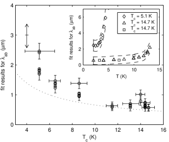
Our versus results are shown in Fig. 8. The dominant sources of error are the uncertainty in (which will be the same for all data points) and the calibration of the probe’s Hall coefficient, /G (which may fluctuate from cooldown to cooldown). Fits with the extremes show that the corresponding error, indicated by the double arrow in the upper left of Fig. 8, is roughly constant for all data points. The uncertainty in translates to a error of roughly of . The in-plane penetration depth decreased as increased. For example, at K, the average value is , while for the highest K it is , where the quoted errors are from the uncertainties in and , respectively.
The in-plane penetration depth is actually a combination of and , which are not equal in YBCO. The anisotropy has been measured to be slightly larger than unity in higher doped samples (see for example Ref. Pereg-Barnea et al., 2004). In-plane anisotropy would lead to a distortion of the otherwise circular field profile of a vortex aligned along the -axis. In principle, our approach could be used to obtain separate values for and if it was performed on a detwinned crystal.
There are several caveats to our measurements. First, it is possible that some of the full vortices identified for fitting were actually partial vortices, especially at the lowest values where fewer full vortices were available for comparison. If a partial vortex stack was fit with Eq. (5), the resulting value would be falsely high. At higher , many more full vortices of consistent appearance were observed. However, it cannot be ruled out that the pancake vortices in the “straight” stacks were not completely axial but rather pinned in a staggered manner resulting in a more spread out vortex field profile. If this were the case, our fits would yield falsely high values since Eq. (5) is for a straight vortex. Thus the most conservative approach to our fit results is to take the values shown in Fig. 8 as upper bounds on the true values of .
For K, our values obtained from vortex fits are close to the values calculated from the low fit (Oe) from Ref. Liang et al., 2005, as shown by the dotted curve in Fig. 8. For K, our values lie slightly above the curve. However, as discussed above, our values should conservatively be treated as upper bounds, so there is not a discrepancy with Ref. Liang et al., 2005.
Our estimates, along with the results of Ref. Liang et al., 2005, give a larger for a given superfluid density in the highly underdoped regime than predicted by the Uemura relation . Other recent experiments have also shown deviations from this relation, such as Pereg-Barnea et al.Pereg-Barnea et al. (2004) in higher doped YBCO crystals and Zuez et al.Zuev et al. (2005) in underdoped YBCO films. These data indicate that thermal phase fluctuations alone cannot explain the suppressed superfluid density in underdoped cuprates. Herbut and CaseHerbut and Case (2004) proposed that low temperature nodal quasiparticles and vortex fluctuations near can explain the observed nonlinearity between and .
References
- Clem (1991) J. R. Clem, Phys. Rev. B 43, 7837 (1991).
- Grigorenko et al. (2002) A. N. Grigorenko, S. J. Bending, A. E. Koshelev, J. R. Clem, T. Tamegai, and S. Ooi, Phys. Rev. Lett. 89, 217003 (2002).
- Beleggia et al. (2004) M. Beleggia, G. Pozzi, A. Tonomura, H. Kasai, T. Matsuda, K. Harada, T. Akashi, T. Masui, and S. Tajima, Phys. Rev. B 70, 184518 (2004).
- Benkraouda and Clem (1996) M. Benkraouda and J. R. Clem, Phys. Rev. B 53, 438 (1996).
- Geim et al. (2000) A. K. Geim, S. V. Dubonos, I. V. Grigorieva, K. S. Novoselov, F. M. Peeters, and V. A. Schweigert, Nature (London) 407, 55 (2000).
- Kirtley et al. (1995) J. R. Kirtley, P. Chaudhari, M. B. Ketchen, N. Khare, S.-Y. Lin, and T. Shaw, Phys. Rev. B 51, 12057 (1995).
- Mannhart et al. (1996) J. Mannhart, H. Hilgenkamp, B. Mayer, C. Gerber, J. R. Kirtley, K. A. Moler, and M. Sigrist, Phys. Rev. Lett. 77, 2782 (1996).
- Liang et al. (1998) R. Liang, D. A. Bonn, and W. N. Hardy, Physica (Amsterdam) 304C, 105 (1998).
- Liang et al. (2002) R. Liang, D. A. Bonn, W. N. Hardy, J. C. Wynn, K. A. Moler, L. Lu, S. Larochelle, L. Zhou, M. Greven, L. Lurio, et al., Physica (Amsterdam) 383C, 1 (2002).
- (10) R. Liang, private communication.
- Guikema (2004) J. W. Guikema, Ph.D. Thesis, Stanford University (2004).
- Chang et al. (1992) A. M. Chang, H. D. Hallen, L. Harriott, H. F. Hess, H. L. Kao, J. Kwo, R. E. Miller, R. Wolfe, J. van der Ziel, and T. Y. Chang, Appl. Phys. Lett. 61, 1974 (1992).
- Davidović et al. (1996) D. Davidović, S. Kumar, D. H. Reich, J. Siegel, S. B. Field, R. C. Tiberio, R. Hey, and K. Ploog, Phys. Rev. Lett. 76, 815 (1996).
- Oral et al. (1996) A. Oral, S. J. Bending, and M. Henini, J. Vac. Sci. Technol. B 14, 1202 (1996).
- Clem (2004) J. R. Clem, J. Supercond. 17, 613 (2004).
- Dolan et al. (1989) G. J. Dolan, F. Holtzberg, C. Feild, and T. R. Dinger, Phys. Rev. Lett. 62, 2184 (1989).
- Hosseini et al. (2004) A. Hosseini, D. M. Broun, D. E. Sheehy, T. P. Davis, M. Franz, W. N. Hardy, R. Liang, and D. A. Bonn, Phys. Rev. Lett. 93, 107003 (2004).
- Liang et al. (2005) R. Liang, D. A. Bonn, W. N. Hardy, and D. Broun, Phys. Rev. Lett. 94, 117001 (2005).
- Gray et al. (1992) K. E. Gray, D. H. Kim, B. W. Veal, G. T. Seidler, T. F. Rosenbaum, and D. E. Farrell, Phys. Rev. B 45, 10071 (1992).
- Clem (1994) J. R. Clem, Physica (Amsterdam) 235–240C, 2607 (1994).
- Mints et al. (2000) R. G. Mints, V. G. Kogan, and J. R. Clem, Phys. Rev. B 61, 1623 (2000).
- Grigorenko et al. (2000) A. N. Grigorenko, S. J. Bending, G. D. Howells, and R. G. Humphreys, Phys. Rev. B 62, 721 (2000).
- Gardner et al. (2002) B. W. Gardner, J. C. Wynn, D. A. Bonn, R. Liang, W. N. Hardy, J. R. Kirtley, V. G. Kogan, and K. A. Moler, Appl. Phys. Lett. 80, 1010 (2002).
- Basov et al. (1995) D. N. Basov, R. Liang, D. A. Bonn, W. N. Hardy, B. Dabrowski, M. Quijada, D. B. Tanner, J. P. Rice, D. M. Ginsberg, and T. Timusk, Phys. Rev. Lett. 74, 598 (1995).
- Koshelev (2005) A. E. Koshelev, Phys. Rev. B 71, 174507 (2005).
- Bulaevskii et al. (1992) L. N. Bulaevskii, M. Ledvij, and V. G. Kogan, Phys. Rev. B 46, 366 (1992).
- Grigorenko et al. (2001) A. Grigorenko, S. Bending, T. Tamegai, S. Ooi, and M. Henini, Nature (London) 414, 728 (2001).
- Bending and Dodgson (2005) S. J. Bending and M. J. W. Dodgson, J. Phys.: Condens. Matter 17, R955 (2005).
- Koshelev (1999) A. E. Koshelev, Phys. Rev. Lett. 83, 187 (1999).
- Uemura et al. (1989) Y. J. Uemura, G. M. Luke, B. J. Sternlieb, J. H. Brewer, J. F. Carolan, W. N. Hardy, R. Kadono, J. R. Kempton, R. F. Kiefl, S. R. Kreitzman, et al., Phys. Rev. Lett. 62, 2317 (1989).
- Uemura et al. (1991) Y. J. Uemura, L. P. Le, G. M. Luke, B. J. Sternlieb, W. D. Wu, J. H. Brewer, T. M. Riseman, C. L. Seaman, M. B. Maple, M. Ishikawa, et al., Phys. Rev. Lett. 66, 2665 (1991).
- Pearl (1966) J. Pearl, J. Appl. Phys. 37, 4139 (1966).
- Kogan et al. (1993) V. G. Kogan, A. Y. Simonov, and M. Ledvij, Phys. Rev. B 48, 392 (1993).
- Kirtley et al. (1999a) J. R. Kirtley, V. G. Kogan, J. R. Clem, and K. A. Moler, Phys. Rev. B 59, 4343 (1999a).
- Kirtley et al. (1999b) J. R. Kirtley, C. C. Tsuei, K. A. Moler, V. G. Kogan, J. R. Clem, and A. J. Turberfield, Appl. Phys. Lett. 74, 4011 (1999b).
- Pereg-Barnea et al. (2004) T. Pereg-Barnea, P. J. Turner, R. Harris, G. K. Mullins, J. S. Bobowski, M. Raudsepp, R. Liang, D. A. Bonn, and W. N. Hardy, Phys. Rev. B 69, 184513 (2004).
- Zuev et al. (2005) Y. Zuev, M. S. Kim, and T. R. Lemberger, Phys. Rev. Lett. 95, 137002 (2005).
- Herbut and Case (2004) I. F. Herbut and M. J. Case, Phys. Rev. B 70, 094516 (2004).