Coriolis Effect in Optics: Unified Geometric Phase and Spin-Hall Effect
Abstract
We examine the spin-orbit coupling effects that appear when a wave carrying intrinsic angular momentum interacts with a medium. The Berry phase is shown to be a manifestation of the Coriolis effect in a non-inertial reference frame attached to the wave. In the most general case, when both the direction of propagation and the state of the wave are varied, the phase is given by a simple expression that unifies the spin redirection Berry phase and the Pancharatnam–Berry phase. The theory is supported by the experiment demonstrating the spin-orbit coupling of electromagnetic waves via a surface plasmon nano-structure. The measurements verify the unified geometric phase, demonstrated by the observed polarization-dependent shift (spin-Hall effect) of the waves.
pacs:
03.65.Vf, 41.20.Jb, 42.15.-i, 42.25.-pIntroduction.— Geometric phase is an inherent feature of the polarization optics that appears under evolution of electromagnetic waves in inhomogeneous and anisotropic media 1 . There are two types of geometric phases: (i) the spin redirection Rytov–Vladimirskii–Berry phase associated with the parallel transport of the wave field under SO(3) variations of the direction of propagation of the wave 2 ; 3 and (ii) the Pancharatnam–Berry phase that occurs under SU(2) manipulations with the polarization state of light 4 ; 5 . In the general case, when both the direction of propagation and polarization state of the wave are varied, the geometric phase becomes more intricate 6 ; 7 ; 8 ; 9 , and a unified geometrical description of the phase requires the tricky Majorana representation 8 .
Another generalization of the geometric phases appears when one considers higher-order wave beams carrying an intrinsic orbital angular momentum (AM) accompanied by a phase vortex 10 . In contrast to spin AM (polarization), which equals , the orbital AM may take arbitrary integer values (we determine AM per one photon in the units of ). The geometric and dynamic properties of light beams bearing orbital AM resemble behavior of massless particles with spin . In particular, the spin redirection Berry phase and the Pancharatnam–Berry phase are generalized to the states of light with 11 ; 12 . While the spin redirection phase is still associated with the parallel transport under SO(3) evolution 11 , the Pancharatnam-type phase arises from SU() manipulation with the modes 12 ; 13 . Accordingly, the Majorana formalism becomes drastically complicated for higher spins 14 .
Whereas the Majorana representation develops the geometrical interpretation, the Berry phase can also be treated dynamically, as a manifestation of the spin-orbit interaction of waves carrying AM 9 ; 11 ; 15 ; 16 . (In using the term “spin-orbit interaction” we refer to the interaction between intrinsic AM and the extrinsic evolution of the wave.) In such approach, the geometric phase turns out to be closely related to the Coriolis effect 17 . Furthermore, it has recently been shown that the spin redirection geometric phase is accompanied by the spin-Hall effect of light 9 ; 11 ; 15 ; 16 ; 18 , i.e., an AM-dependent displacement of the wave trajectory, which argues in favor of the dynamical interpretation of the Berry phase.
In this Letter, we develop and unify the dynamical approach to the geometric phases in optics. We show that in the most general case, when a wave carrying an arbitrary AM changes its direction of propagation and state, the geometric phase is still given by a rather simple expression stemming from the Coriolis effect. The theoretical conclusions are confirmed experimentally using a focusing surface plasmon nano-structure. We observe that the geometric phases of partial waves bring about a polarization-dependent shift of the resulting intensity distribution which sheds light on the nature of the spin-Hall effect and explains other recent experiments. Our formalism can be equally applied to a number of problems outside the optical field. Indeed, the Coriolis effect is responsible for the Berry phase in classical 19 and quantum 20 systems, and the spin-Hall effect occurs in the evolution of various quantum particles 16 ; 21 .
Coriolis effect.— The total intrinsic AM of a paraxial wave equals , where is the vector indicating the direction of propagation of the wave ( is the wave vector), and is the mean helicity of the wave which has a continuous spectrum in the range .
We consider a coherent non-collinear bundle of waves which are either (A) emitted or (B) scattered by a motionless body, Fig. 1. Let the observer measures the wave characteristics in a coordinate frame moving across the bundle and, hence, rotating with some instantaneous angular velocity , Fig. 1. Although the system is stationary in the laboratory reference frame, the waves successively measured by the observer are related by the precession equation: . The frequencies of the waves measured in the rotating frame suffer the shift (case A) 22
| (1) |
This shift corresponds to an analogous term in the wave Hamiltonian which is responsible for the spin-orbit interaction. In the case (B), the observer will register the frequency difference between the input and output waves:
| (2) |
where the subscript 0 indicates the characteristics of the input wave, Fig. 1b.
The frequency shift (1) is a manifestation of the Coriolis effect in the non-inertial reference frame. It is identical to the frequency shift of the rotational modes of the Foucault pendulum staying on the rotating Earth ( is orthogonal to the Earth’s surface, and the angle between and is determined by the latitude , Fig. 1) 19 . The shifts (1) and (2) are similar to the angular Doppler shifts (see in 10 ) that are produced as the medium moves with respect to observer with the angular velocity . However, unlike the real angular Doppler shift, there is no real rotation of the medium and energy exchange in our case. The Coriolis shifts (1) and (2) are artefacts of the rotation of the reference frame, and they indicate the inertia of the wave field.
Unified geometric phase.— The Berry phase for waves evolving in stationary media is a manifestation of the Coriolis effect. Indeed, the non-inertial reference frame appears when the wave phase is measured in the coordinate frame attached to the varying direction of propagation 17 (the case of the spin redirection phase) or to the polarization ellipse (the case of the Pancharatnam phase). In both cases, the geometric phase originates from the Coriolis shift (1):
| (3) |
This phase is added to the wave phase calculated in a parallel-transport (i.e., with ) reference frame (see Ref. 10c). Although we considered the temporal evolution of the coordinate frame, Eq. (3) holds true for spatial evolution along a coordinate as well. This case is described via the substitution
| (4) |
where is the rate of rotation of the coordinate frame with respect to the coordinate.

First, when the wave in an AM eigenstate with integer propagates along a curved trajectory (so that the direction is varied), and is the coordinate along this trajectory, then the phase is the spin redirection Berry phase 17 . If is given by the spherical angles in the laboratory frame, then the attached reference frame , Fig. 1, suffers rotation with and . Then, Eqs. (3) and (4) result in
| (5) |
which is the known expression for the spin redirection Berry phase 1 ; 3 ; 17 ; 23 .
Second, let the wave now propagates along the -coordinate in a fixed direction , but the helicity is continuously varied. This is accompanied by mixing of AM eigenstates and appearance of an oriented transverse structure of the wave (e.g., polarization ellipse). In the simplest case of , the state of the wave can be represented on the Poincaré (Bloch) sphere. In the spherical coordinates on the Poincaré sphere, the wave helicity equals , whereas the angle of rotation of the polarization ellipse is . The wave-accompanying coordinate frame with attached to the polarization ellipse rotates with the angular velocity , and Eqs. (3) and (4) yield
| (6) |
which is the known expression for the Pancharatnam–Berry phase 1 ; 5 ; 23 . For higher angular momenta, , the wave state is described by structure 12 ; 13 , and cannot be represented on the Poincaré sphere.
Finally, in the most general case of continuous evolution of a wave carrying an AM , with both the direction and absolute value of being varied, the higher-spin Majorana representation can be evoked. This advanced geometrical formalism represents the wave state by a set of vectors , , on a unit sphere generalizing the sphere of directions 14 . The geometric phase for cyclic evolutions is expressed by a rather complicated contour integral involving motion of these vectors on the sphere. Surprisingly, substitution of the rotational evolution reduces this integral to the simple expression (3) for (see Eq. (20) in 14 ). This expression remains valid for non-cyclical evolutions provided the measurements are made in the reference frame attached to the direction of propagation and the transverse structure of the field.
Similarly, the phase difference due to Eq. (2),
| (7) |
determines the geometric phases in systems with an abrupt transformation of the AM from to and a continuous evolution of . In this case, we imply that the incident wave is in an AM eigenstate and . Otherwise, an additional geometric phase may appear due to motion of the -accompanying frame with respect to the the incident wave (see below).
Experiment: Geometric phase producing the spin-Hall effect.— The experiment was performed utilizing surface plasmon-polariton waves and their strong polarization coupling sensitivity together with high surface confinement. The metallic sample, Fig. 2, has a semi-circular corrugation (the inner radius is 1640 nm) that acts as a lens for the surface plasmons ( nm) 24 . The grating was etched by a focused ion beam in a 100-nm-thick gold film evaporated onto a glass wafer. The coupling grating (period of 500 nm) was accompanied by a Bragg grating (period of 250 nm) from the outside. The grating grooves enclosed an azimuthal angle from 5 to 175 degrees in order to avoid resonant edge effects. The sample was illuminated from the bottom by a green laser (”Verdy” doubled Nd:Yag, nm), while the near-field intensity of the surface plasmons was measured by a Near-field Scanning Optical Microscope (NSOM; Nanonics Multiview 2000) in a non-contact mode.
The scheme of the experiment involving wave vectors and polarizations is shown in Fig. 2. The incident light, propagating along the axis, is right- or left-hand circularly polarized, (AM eigenstates). The coupling grating on the surface of the sample transforms the propagating waves into surface plasmons. They are linearly polarized (the electric field is normal to the metal surface), so that , and have the vectors directed normally to the grating in the plane. Neither the spin redirection phase nor the Pancharatnam phase is applicable in this system, since the wave changes both its direction of propagation and polarization state. At the same time, the phase can be readily calculated using Eq. (7) with Eq. (4). The plasmon-accompanying coordinate frame is locally attached to the grating with and . The azimuthal angle along the grating equals to the azimuthal angle of the plasmon wave vector and can be taken as the coordinate in the above formalism. In this manner, , and the phase difference appearing at the grating equals
| (8) |

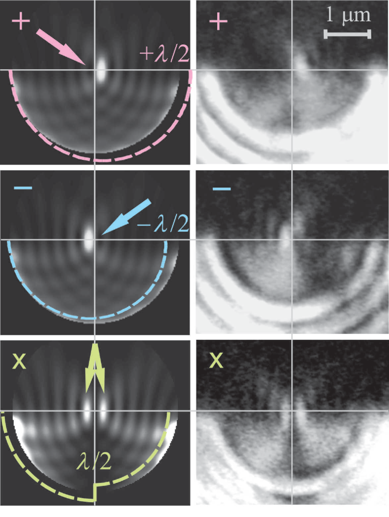
Geometric phase (8) describes an azimuthal phase gradient in the plasmon field that depends on the polarization of the incident light. This changes the wave phase front into a segment of spiral with the pitch and the helicity dependent on the polarization of the incident wave, Fig. 3. As the surface plasmons are focused by the semi-circular geometry of the sample, the phase (8) modifying the phase front brings about the transverse shift of the resulting focal spot. This shift can be estimated as
| (9) |
Since the shift (9) is proportional to the helicity of the incident wave, , it should be regarded as a spin-Hall effect of electromagnetic waves 9 ; 11 ; 15 ; 16 ; 18 . The spin-Hall effect originates from the polarization-dependent geometric phases (8) of partial waves forming the confined field in the focus. The polarization-dependent shift (9) is clearly seen both in experimental measurements and in numerical calculations processing the evolution of field with the phase (8), Fig. 3, thereby, confirming the geometric phase in the system.
Being a superposition of the right- and left-hand circular modes, the linearly -polarized incident wave (which is not an AM eigenstate) brings about a split double spot in the output plasmon field, Fig. 3, cf. 24 . Such a field distribution is similar to a beam and has a phase singularity: a jump at , Fig. 3. This phase jump is a Panchratnam-type phase that arises due to a rotation of the polarization ellipse of the incident light with respect to the coordinate frame attached to the grating.
Discussion.— We have shown that the geometric phase is unified in terms of spin-orbit interaction and Coriolis effect and is given by a simple expression. Our experiment has verified the unified geometric phase in a rather complex system including light and surface plasmon-polaritons. The results reveal the nature of the spin-Hall effect – the spin-dependent geometric phase of partial waves brings about a spin-dependent transverse shift of the resulting confined wave field. In contrast to semiclassical theories implying paraxial confined waves 15 ; 16 ; 18 ; 21 , our experiment dealt with a highly non-paraxial field. As a result, the transverse shift is comparable with the focal spot width and is readily detected.
Polarization-dependent displacements of light beams diffracted by a space-variant grating producing the Pancharatnam–Berry phase have been observed in 25 . A polarization-dependent transverse shift of the focal spot in lenses has also been reported in papers 26 ; 27 . In 26 this effect was explained in the context of the spin-orbit interaction of photons in a vacuum. In a recent paper 27 , deformation and shifts of the wave intensity in the focus of a high-numerical-aperture lens were treated as manifestations of the Pancharatnam–Berry phase and have been associated with the spin-Hall effect of light. Our results can be applied to the systems in 24 ; 25 ; 26 ; 27 , clarifying the interrelations between the spin-orbit interaction, geometric phase, and spin-Hall effect of light.
The work by K.B. is supported by the Linkage International Grant of the Australian Research Council.
References
- (1) S.I. Vinitskii et al., Sov. Phys. Usp. 33, 403 (1990); Geometrical Phases in Physics, edited by A. Shapere and F. Wilczek (World Scientific, Singapore, 1989).
- (2) S.M. Rytov, Dokl. Akad. Nauk. SSSR 18, 263 (1938); V.V. Vladimirskii, ibid. 31, 222 (1941). See in Ref. 1a.
- (3) J.N. Ross, Opt. Quantum Electron. 16, 455 (1984); R.Y. Chiao and Y.S. Wu, Phys. Rev. Lett. 57, 933 (1986); A. Tomita and R.Y. Chiao, ibid. 57, 937 (1986); M.V. Berry, Nature 326, 277 (1987).
- (4) S. Pancharatnam, Proc. Indian Acad. Sci. A 44, 247 (1956). Reprinted in Ref. 1b.
- (5) M.V. Berry, J. Mod. Opt. 34, 1401 (1987); R. Bhandari and J. Samuel, Phys. Rev. Lett. 60, 1211 (1988); R. Simon et al., ibid. 61, 19 (1988).
- (6) R. Bhandari, Phys. Lett. A 135, 240 (1989).
- (7) H. Jiao et al. Phys. Rev. A 39, 3475 (1989).
- (8) J.H. Hannay, J. Mod. Opt. 45, 1001 (1998).
- (9) K.Y. Bliokh, D.Y. Frolov, and Y.A. Kravtsov, Phys. Rev. A 75, 053821 (2007).
- (10) Optical Angular Momentum, edited by L. Allen, S.M. Barnett, and M.J. Padgett (Taylor & Francis, London, 2003); L. Allen, M.J. Padgett, and M. Babiker, Prog. Opt. 39, 291 (1999); A. Bekshaev, M. Soskin, and M. Vasnetsov, arXiv:0801.2309.
- (11) K.Y. Bliokh, Phys. Rev. Lett. 97, 043901 (2006); C.N. Alexeyev and M.A. Yavorsky, J. Opt. A: Pure Appl. Opt. 8, 752 (2006); I.V. Kataevskaya and N.D. Kundikova, Quantum Electron. 25, 927 (1995).
- (12) S.J. van Enk, Opt. Commun. 102, 59 (1993); M.J. Padgett and J. Courtial, Opt. Lett. 24, 430 (1999); E.J. Galvez et al., Phys. Rev. Lett. 90, 203901 (2003).
- (13) G.S. Agarwal, J. Opt. Soc. Am. A 16, 2914 (1999); L. Allen, J. Courtial, and M.J. Padgett, Phys. Rev. E 60, 7497 (1999).
- (14) J.H. Hannay, J. Phys. A: Math. Gen. 31, L53 (1998).
- (15) V.S. Liberman and B.Y. Zel’dovich, Phys. Rev. A 46, 5199 (1992).
- (16) A. Bérard and H. Mohrbach, Phys. Lett. A 352, 190 (2006).
- (17) S.G. Lipson, Opt. Lett. 15, 154 (1990).
- (18) K.Y. Bliokh and Y.P. Bliokh, Phys. Rev. E 70, 026605 (2004); Phys. Lett. A 333, 181 (2004); M. Onoda, S. Murakami, and N. Nagaosa, Phys. Rev. Lett. 93, 083901 (2004); K.Y. Bliokh and Y.P. Bliokh, ibid. 96, 073903 (2006); C. Duval, Z. Horváth, and P.A. Horváthy, Phys. Rev. D 74, 021701(R) (2006); O. Hosten and P. Kwiat, Science 319, 787 (2008).
- (19) G.I. Opat, Am. J. Phys. 59, 822 (1991); A. Khein and D.F. Nelson, ibid. 61, 170 (1993).
- (20) Y.A. Serebrennikov, Phys. Rev. B 73, 195317 (2006).
- (21) G. Sundaram and Q. Niu, Phys. Rev. B 59, 14915 (1999); S. Murakami, N. Nagaosa, and S.-C. Zhang, Science 301, 1348 (2003).
- (22) B. Mashhoon, Phys. Rev. Lett. 61, 2639 (1988).
- (23) The phases (5) and (6) are determined in the coordinate frame rotated with azimuthal angles and , respectively. Subtraction of this rotation leads to the substitution and , and integrals in Eqs. (5) and (6) give the solid angles enclosed by the wave evolution on the corresponding spheres 1 ; 2 ; 3 ; 4 ; 5 .
- (24) L. Yin et al., Nano Lett. 5, 1399 (2005); F. Lopez-Tejeira et al., Nature Phys. 3, 324 (2007).
- (25) Z. Bomzon et al. Opt. Lett. 27, 1141 (2002); E. Hasman et al., Prog. Opt. 47, 215 (2005).
- (26) N.B. Baranova, A.Y. Savchenko, and B.Y. Zel’dovich, JETP Lett. 59, 232 (1994); B.Y. Zel’dovich, N.D. Kundikova, and L.F. Rogacheva, ibid. 59, 766 (1994).
- (27) Z. Bomzon and M. Gu, Opt. Lett. 32, 3017 (2007).