Ground states of colloidal molecular crystals on periodic substrates
Abstract
Two dimensional suspensions of spherical colloids subject to periodic external fields exhibit a rich variety of molecular crystalline phases. We study in simulations the ground state configurations of dimeric and trimeric systems, that are realized on square and triangular lattices, when either two or three macroions are trapped in each external potential minimum. Bipartite orders of the checkerboard or stripe types are reported together with more complex quadripartite orderings, and the shortcomings of envisioning the colloids gathered in a single potential minimum as a composite rigid object are discussed. This work also sheds light on simplifying assumptions underlying previous theoretical treatments and that made possible the mapping onto spin models.
I Introduction
Colloidal suspensions provide valuable systems for the study of collective effects and phase transitions (see e.g Hunter or more specifically JPCM2 and references therein). Recent advances in optical trapping techniques have enlarged the whole field and opened the possibility to obtain quasi two-dimensional systems, which can furthermore be subject to an external potential. A possibility to realize such external perturbations is through the interference of laser beams, the typically micron-sized colloids being attracted to the regions of highest intensity: for instance, unusual phases have been reported in the case of 1D troughs Bech2001 , such as floating solids or locked smectic phases Radzi ; BechFrey .
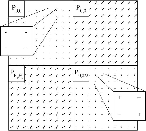
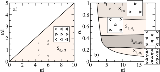
The situation of a two-dimensional periodic substrate, some instances of which can be realized by 3 laser beams, is remarkably rich and has been addressed experimentally Bech2002 , numerically RO ; half-integer ; RO2005 and analytically Agra ; Sarlah . The control parameters governing the static behaviour are numerous : filling fraction (mean number of colloids per substrate minimum), pinning amplitude (trap strength, increasing with laser intensity), temperature, and concerning the substrate geometry, lattice spacing and aspect ratio (i.e rectangular unit cell instead of a square one). In addition, the colloids considered are highly charged objects, so that the Debye length of the suspension, modified by changing the salt content, is a crucial parameter. In the present paper, we concentrate on the experimentally relevant ground state of those 2D systems, where the long range orientational order observed has been coined “colloidal molecular crystal”. If the external laser potential is strong enough, the colloids are irreversibly bound to the potential minima. In cases when more than one colloid is trapped in a single minimum we speak of a ”colloidal molecule”. Its size is determined by the interplay between light forces and interparticle repulsion. Figure 1-a) provides an illustration of typical phases observed when the ratio of the total number of colloids in the system to the total number of external potential minima is exactly two. Whereas defects are present at finite temperature, we observe that the ground state is free of such objects, so that each trap captures exactly two colloids.
The purpose of the present paper is twofold. The first goal is to provide a thorough numerical investigation of orientational ordering in colloidal molecular crystals on two-dimensional periodic substrates. We will focus on stoichiometries 2 and 3, where dimers and trimers are formed, respectively, with the underlying square or triangular symmetry for the potential. We will also address the situations where the corresponding lattice unit cell is distorted by changing the aspect ratio . The second objective is to critically test several assumptions that led to the theoretical frameworks used in Refs. Agra ; Sarlah to study such problems. In section II, we will start with an approach, common to Refs Agra ; Sarlah , where the composite objects (-mers) formed in each trap are considered as rigid entities with an orientational degree of freedom only, while the confining potential is taken into account implicitly. This allows for a significant reduction of the complexity of the problem. Reference phase behaviour is thus obtained, which will be tested against more realistic simulations in Section III, where each colloid is resolved and the confining potential explicitly accounted for. Finally, we will also test the relevance of the various effective potentials used in Agra to construct a tractable Hamiltonian allowing for analytical progress. Our main finding and the ensuing consequences will be summarised in section V.
II The rigid -mer approach
The integer number of colloids that gather in a light potential minimum rque are subject to gradient forces arising from the dielectric mismatch between colloids and the solvent, and light pressure BB04 . Under such forces alone, the colloids have a preference for regions of highest laser intensity. In addition, the (spherical) colloids interact through strong mutual repulsion, considered to be of a screened Coulomb form DLVO
| (1) |
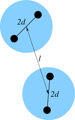
where is the distance between the centres of masses of macroions and , is the Debye length rque2 , and is an irrelevant prefactor. To a large extent, colloids in a given trap experience the repulsion from their “trap-mates” only, and interactions with colloids in other traps are of little relevance to determine the shape that the -mer adopts within a trap. We therefore assume here that the antagonistic effects of light interaction and Coulomb repulsion lead to the formation of rigid composite objects with -fold symmetry (e.g. equilateral triangles for trimers when there are 3 colloids per trap). This is the basic assumption of Refs Agra ; Sarlah , for which the relevant ground state dimensionless parameters are , and aspect ratio , where is the distance between the centres of two adjacent traps, is the distance between the centre of the trap and the centre of one of the colloids forming an -mer (so that in the dimeric case, is the dimer extension, see Fig. 1-b)).
The rigidity assumption lumps substrate potential effects into the length scale (increasing the well’s amplitude decreases ). The position of each -mer is then described by a unique angular coordinate, while its centre-of-mass always coincides with trap minimum. Unlike in Ref. Sarlah , we do not assume that such angles are discrete with values dictated by the lattice geometry: it is indeed of interest to realize that Coulomb repulsion alone is able to select well defined orientations that do not match any of the underlying lattice principal direction. Finding the ground state of a system of -mers therefore amounts to minimising the energy function (1) with respect to angles rque3 .
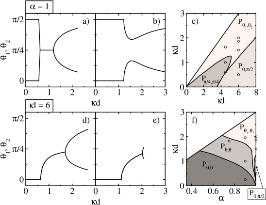
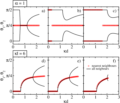
For the simplest case of dimers () on a square () or rectangular () lattice, we found that in the lowest energy configuration –obtained by a simulated annealing technique–, the system adopts a bi-partite structure of the checkerboard type. The long range orientational order is therefore characterised by two angles and , which define a phase denoted , see Fig. 1. Interestingly, the angles and are constant in some parameter range, while they vary continuously in other parameter regions. This is illustrated in Fig. 2. The low regions of graphs a) and b) are such that , a situation coined “antiferromagnetic” in previous studies and illustrated in the lower right corner of Fig. 1. Starting from with a square lattice (Fig. 2-b) and slightly distorting the lattice into a rectangular one with aspect ratio 0.9, we observe that the antiferromagnetic phase disappears and turns into a ferromagnetic one , for small enough dimer extensions (small ), see Figs. 2-d) and -e). For higher , a tilted ferromagnetic phase appears the most stable, and changes into a tilted antiferromagnetic (Figs.2-d, -e). Mild parameter differences therefore trigger significant orientational changes: for instance, at , all phases are antiferromagnetic-like (see graph b)) while at (graph a)) there exists a window around with a ferromagnetic ordering. Note also that the upper part of phase diagram c) corresponds to cases where , which is ruled out since a given trap cannot extend further than half the inter-trap distance. Similarly, the forbidden upper region of diagram f) corresponds to .
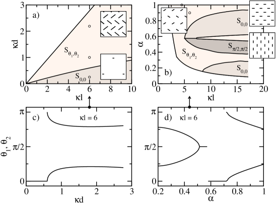
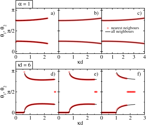
When the lattice geometry is triangular, we have observed the formation of stripes Bech2002 ; RO , and the corresponding phases are denoted (the stripes are of the same bi-partite family as the order reported on the square lattice, since the checkerboard structure itself is made up of parallel stripes). The main results are summarised in Fig. 3. The upper left and lower left regions of graphs a) and b) respectively are forbidden regions where some configurations of the rigid trimers in neighbouring traps would lead to overlaps. For a given aspect ratio, two ground states are generically observed : a herringbone order (see e.g. the upper inset of Fig. 3-a)) and a ferromagnetic one where dimers align. The sequence of these two phases as parameters are modified is quite complex, particularly so when the aspect ratio is changed. The lattice with maximal symmetry appears singular in that the only phase selected there is the herringbone one. This qualitatively confirms the results of Sarlah . The case of trimers on a square or rectangular lattice is somewhat simpler, with only the stripe order observed (see Fig. 4-a)). When the trimers are put on the triangular lattice, several stripe phases are possible, but roughly speaking, there is a unique type of order for a given aspect ratio, see Fig. 4-b).
III Towards a more complete description : effects of flexibility
To test the relevance of the rigidity assumption we now explicitly take into account the confining potential in the simulations. In order not to introduce any orientational bias, we consider an isotropic (harmonic) confining potential , so that the total dimensionless energy of colloid reads:
| (2) |
where denotes the distance between the centre of mass of colloid and the trap centre. The relevant parameters are now , which measures the relative strength of the light confinement against the Coulomb repulsion and therefore sets the -mer size denoted in section II, and again the aspect ratio. We have performed Monte Carlo simulations of this “flexible” model, which has degrees of freedom whereas the “rigid model” only has degrees of freedom.
The results are shown in Figs. 5, 6 and 7, and depend on the particular situation. The comparison flexible/rigid was performed by first implementing simulated annealing for the flexible model, measuring the resulting -mer size, and using the corresponding value of in a rigid-model simulation. For dimers on the square/rectangular lattice, we always found an excellent agreement between both routes, see Fig. 5 where three typical bipartite orders are shown in the insets. On the triangular lattice, we found that the qualitative features put forward in section II remain correct (see e.g. the configuration shown in the inset of Figure 6), while on closer inspection, some differences arise. Indeed, the histograms of distances to trap centre and tilt angle in Figure 6 clearly reveals the mismatch between the rigid and flexible ground states that are respectively of bipartite and of quadripartite type (the inset shows the new unit cell by a shaded area). Correlating the histograms to the snapshot of the inset, it appears that the top row of the inset corresponds to the most intense peak in the distribution, and to the two extreme peaks in at and . Conversely, the second row from the top has colloids contributing to the two smaller peaks in that weight half the previous one, and contributing to the peaks at . It can be seen that the average is , as it should from the definition of in the flexible case.
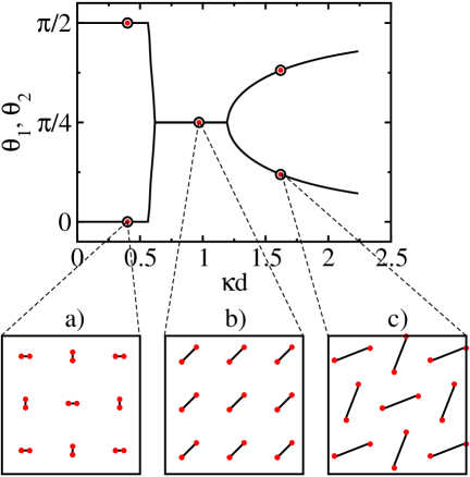
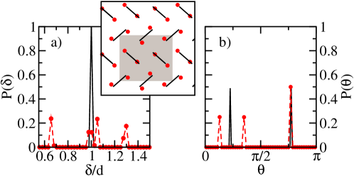
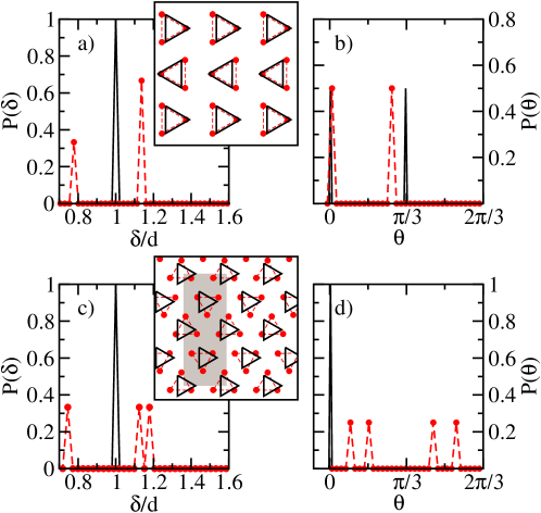
Figure 7 shows similar results for trimers on both rectangular and triangular lattices. On the rectangular lattice, the main difference with the rigid case (where the trimer centre is imposed to coincide with the trap centre), lies in an off-centre shift, see the inset of graph a). Graphs a) and b) corroborate and quantify this visual observation. On the triangular lattice, the effect is more spectacular. While the rigid model leads to an order where all trimers align in the same direction ( fashion), due account of the internal flexibility of the trimers yields an order that is visually reminiscent of a stripe phase , but that is in reality more complex. This can be appreciated by comparing the configurations in the first and third rows from the top of the inset in graph c) (or equivalently second and fourth): an off-centre shift of the triangles may be observed, and substantiated by the histograms of graphs c) and d). Here again, the order selected is of tetrapartite form, with a unit cell shown by the shaded area, and not bipartite as found in section II.
IV On the relevance of different approximation schemes
In the previous section, we have shown that assuming the trapped colloids to form a rigid composite object may be incorrect in some cases. Here, we address the applicability of two other classes of simplification of the original model provided by the energy function (2).
IV.1 The nearest neighbour interactions
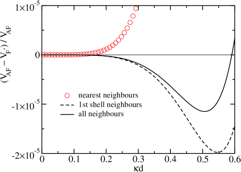
The first simplification, considered in both Refs. Agra and Sarlah consists in restricting colloid interactions to partners in nearest neighbour traps. Given the exponential character of screened Coulombic law (1), this seems an a priori reasonable assumption, provided both the distance between adjacent traps () and the closest distance between colloids () are large enough compared to Debye length . The comparison between the two approaches is displayed in Fig. 8 for dimers on a square or rectangular lattice, and on Fig. 9 for dimers on a triangular lattice. We consider only the rigid dimers, which has been shown to be sufficient in section III, see Fig. 5). The above argument leads to believe that for large enough and small enough , interactions beyond the nearest neighbours should be immaterial. This can be observed in Fig. 8, where the angles and (those of the bipartite checkerboard structure) are plotted against for six different () combinations. The nearest neighbours approximation generally works well when with, however, the surprise that at and small , the nearest neighbour route is quantitatively wrong, leading to a tilted ferromagnetic phase instead the antiferromagnetic (see Fig. 8a)). A comparison between the energies of the different phases is performed in Fig. 10. Surprisingly, the relative energy difference between ferromagnetic and antiferromagnetic phases is minute (see the -scale) and explains why including second nearest neighbours is essential to get the correct phase behaviour. The dashed line in Fig. 10 is obtained by summing over the four nearest neighbour traps and over the four next-nearest corner traps in the rectangular array. Restricting to nearest neighbours leads to the prevalence of the tilted ferromagnetic (symbols), which is incorrect, although energetically very close to the antiferromagnet. When is increased, this quasi degeneracy disappears, and including next nearest neighbours in the analysis becomes irrelevant.
In the case of the triangular lattice, the nearest neighbour approximation is more efficient than on the rectangular lattice, as can be seen in Fig. 9. The reason for this is most likely that in the triangular lattice where there are six nearest neighbour sites, the next-nearest neighbour distance is times larger than the nearest neighbour one. On a square lattice on the other hand, there are four nearest neighbour sites and the next-nearest distance is only a factor larger. The situation is thus less favourable for nearest neighbour truncation.
IV.2 The large-distance approximation
The second simplification enforced in Agra with the purpose to allow for the construction of a tractable Hamiltonian, which can be mapped onto a spin model, amounts –within the rigid scenario– to considering the leading order term only in the large distance expansion of the interaction potential. The reason for doing so is again to focus on the large case, with the technical bonus that then, interactions between 2 -mers in different traps may be written in a factorized way. To be specific, the large distance potential of interaction between two dimers labelled 1 and 2, of size , with centre-of-mass/centre-of-mass separation reads
| (3) |
where and is the angle between vector and the direction defined by dimer . Similar considerations prove generically fruitful to discuss interactions between anisotropic colloids in the low density regime JPCM1 ; EPJE .
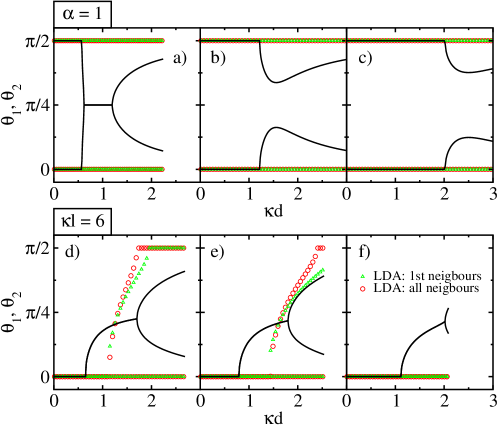
It can be seen in Figure 11 that for low , the corresponding predictions fare favourably against the results of the full expression (1). However, the truncated approach always predicts the antiferromagnetic phase in the square case Agra , and misses the tilted antiferromagnet (see the top row). On a rectangular lattice, it correctly captures the transition from a ferromagnet to tilted ferromagnet, but overestimates the threshold (see the bottom row), to such an extent that it can exceed , the maximum allowed value of (see graph f)). The failure at larger has a different origin from the one observed in Fig. 8, and could have been anticipated by computing the sub-dominant terms in expression (3). For the sake of clarity, we focus here on the electric potential created by a dimer, a simpler but related object than the dimer-dimer potential considered in (3); the sum of the two screened Coulomb terms associated to each colloid may be written
| (4) |
where , defined as above, is the angle under which the dimer is seen from a distance . Neglecting the second factor on the right hand side (which leads to Eq. (3) for the interaction) is only justified provided . Finally, we note that although the parameters in Figs. 8 and 11 are exactly the same, truncating colloid interactions to nearest neighbour traps only makes little difference if the potential is of the form (3). This is at variance with what can be observed in Fig. 8. We are back here to the message conveyed by Figure 10, that minor modifications of the original problem may significantly alter the preferred phase.
IV.3 The discrete angles approximation
In reference Sarlah , an effective Potts-like Hamiltonian was constructed by assuming rigid molecules of fixed sizes placed on the lattice points, restricting the orientations of the molecules to discrete values compatible with the lattice symmetry and by considering the nearest neighbour interactions – Yukawa interactions between colloids in neighbouring traps. Since the phase behaviour studied in Sarlah pertains to triangular substrate potentials, the nearest neighbour approximation seems well justified, see Fig. 9. The restriction to discrete angles, which rests on the remark that the confinement potential exhibits some preferred directions, however deserves a more careful discussion.
For concreteness, we consider in the triangular geometry case, a confinement potential of the same form as in Ref. RO :
| (5) |
The iso- lines are isotropic (circular) in the vicinity of the minima, with an anisotropy that increases with increasing energy . As a consequence, the confinement potential anisotropy is all the more important as the -mer is more extended (large ), but this parameter range corresponds to a situation of strong Coulombic repulsion where details of the light potential may not matter. It is therefore not straightforward to anticipate the relative ranges of applicability of the discrete angle approximation of Sarlah , and of the isotropic confinement potential approach followed in this paper, which leads to Figs. 1-11.
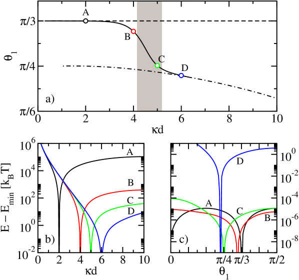
To answer this question, we have minimised the total energy , with respect to the angular orientation of the dimer. Such an approach takes due account of the interplay between the realistic potential (5) and Coulombic interactions. The ground state results are shown in Fig. 12, for the same parameters as in the experiments of Ref Bech2002 : , . The dimers are assumed to form the herringbone structure , where due to the symmetry, we may assume (see Fig. 3). For a given ratio between the light confinement and the strength of the Yukawa interaction, the total energy has been minimised with respect to the radial () and angular () positions of the colloid inside the trap. The resulting angles are plotted against in Fig.12(a), see the solid line. For comparison, the lower dot-dashed curve is the result obtained with the isotropic potential (angles selected by the Yukawa interactions). The upper dashed curve is the constant angle assumed in Sarlah . It appears that the angles are compatible with the pure Yukawa prediction at large values of . In essence, although the confinement potential is more anisotropic at large (corresponding to small ), the Yukawa term nevertheless dominates the total energy so that the isotropic potential approach becomes correct. Conversely, the discrete angle approach appears more relevant for small colloidal molecules.
In Fig. 12(b) we show the radial dependence of the total energy, fixing to its optimal value. The total energy is obtained assuming the experimentally realistic value , the value used also in Sarlah . Larger molecules have weaker radial binding energies and are therefore more prone to fluctuate at finite temperature. In Fig.12(c), we plot the angular dependence of the total energy at fixed . The depth of the minimum can be understood as the angular binding energy. This binding energy is of several at large , while it is very small at small , in the regime rque101 . The assumption of discrete angles therefore fails at large (weak light potentials) and leads to the correct results only at small , where, however, due to the shallow binding in the angular direction, there is no a-priori reason to justify it but for ground state properties.
The parameter regime of the experiments Bech2002 is marked as a shaded area in Fig. 12(a). Interestingly, the experimental situation is somewhat intermediate between both limiting regimes and neither of the approaches seems to be perfectly appropriate. However, other realizations of the light confinement are possible, like creating isotropic optical point traps instead of using the interference patterns as in Bech2002 . For such an experiment, the present approach – the lower curve in Fig.12(a), corresponding to the isotropic trap – would be relevant.
Finally, we also note that numerical simulations of colloidal molecules in the anisotropic light confinement (5) have been performed in RO . The parameters studied there () are nevertheless quite distant from those of the experiments Bech2002 where . In an aqueous solution, cannot be achieved with 3 size colloids as used in Bech2002 , since the inverse Debye length is bounded from below by the solvent dissociation. Moreover, in the regime , the pair-wise additivity assumption leading to the Yukawa potential is questionable, and many-body effects could play an important role.
V Conclusion
We have provided a numerical analysis of the type of long range orientational orders selected in so-called colloidal molecular crystals, where a given integer number of colloids is trapped in each potential minimum of a light lattice. We investigated the cases of dimers () and trimers () on both square and triangular lattices, together with deformed geometries obtained when a given direction of the original lattice is expanded or shrunk by a factor . The sequence of phases reported is rich. For triangular lattices mostly, and although we were only interested in the lowest energy configuration, we have uncovered the relevance of the flexibility of the -mers in a given trap, whereas previous approaches envisioned those composite objects as a rigid entity. In most cases, the qualitative predictions derived within the rigid picture appear qualitatively correct though. We have also addressed the adequacy of truncating interactions to colloids located in nearest neighbour traps, and found that in some cases, the quasi degeneracy between states of different orientational orders makes second nearest neighbours and possibly more remote shells relevant.
We emphasise that the pinning potential we considered is of isotropic form, and therefore does not favour any orientation of the trapped -mers. On the other hand, it was assumed in Ref. Sarlah that the pinning potential itself leads to a discrete set of possible orientations, which were supposed to match the lattice symmetry. In particular, such an assumption would only be compatible with the ferromagnetic and antiferromagnetic phases for dimers on the square lattice. Our investigation shows that several other tilted phases exist, with an angular selection due to Coulombic repulsive interaction alone. Instead of a discrete set of predefined angles we find that the angular coordinates change continuously with parameters. We have explored in detail the limits of validity of both assumptions and have concluded that working with discrete angles can only be justified if the light confinement is very strong or when colloids repel weakly. We have shown however that the angular confinement is very weak in this regime.
Acknowledgements: We would like to thank Frédéric van Wijland for useful discussions and P. Ziherl for carefully reading the manuscript. The work was supported by the Slovenian Research Agency through grants P1-0055 and Z1-9303. We acknowledge the support of the bilateral program Proteus supported by the slovenian Research Agency and the french Ministère des Affaires Etrangères et Européennes.
References
- (1) R.J. Hunter, Foundations of colloid science, Oxford University Press (2005).
- (2) Y. Levin, E. Trizac and L. Bocquet, J. Phys.: Condens. Matt. 15, S3523 (2003).
- (3) C. Bechinger, M. Brunner and P. Leiderer, Phys. Rev. Lett. 86, 930 (2001).
- (4) L. Radzihovsky, E. Frey and D.R. Nelson Phys. Rev. E 63, 031503 (2001).
- (5) C. Bechinger and E. Frey J.Phys.: Condens. Matter 13, R321 (2001).
- (6) M. Brunner and C. Bechinger, Phys. Rev. Lett. 88, 248302 (2002).
- (7) C. Reichhardt and C.J. Olson, Phys. Rev. Lett. 88, 248301 (2002).
- (8) C.J. Olson-Reichhardt and C. Reichhardt, J. Phys. A: Math. Gen. 36, 5841 (2003).
- (9) C. Reichhardt and C.J. Olson-Reichhardt, Phys. Rev. E 71, 062403 (2005).
- (10) R. Agra, F. van Wijland and E. Trizac, Phys. Rev. Lett. 93, 018304 (2004).
- (11) A. Sarlah, T. Franosch and E. Frey, Phys. Rev. Lett. 95, 088302 (2005); A. Sarlah, E. Frey and T. Franosch, Phys. Rev. E 75 021402 (2007).
- (12) Non integer situations have been addressed (see half-integer ; RO2005 ), but will be left aside in the present analysis.
- (13) M. Brunner and C. Bechinger, Progress in Colloid and Polymer Science 123, 156 (2004).
- (14) B.V. Derjaguin and L. Landau, Acta Physicochim. URSS 14 633 (1941); E.J.W. Verwey and J.T.G. Overbeek, Theory of the Stability of Lyophobic Colloids (Elsevier, Amsterdam, 1948).
- (15) While colloidal positional degrees of freedom are limited to a 2D plane, microions and solvent molecule are not subject to confinement, which results in a traditional three-dimensional-like screened Coulomb interaction between macroions.
- (16) Strictly speaking, expression (1) is not an energy but a free energy since it includes an entropic contribution from the microions; we also stress that the ground state we consider are reached at constant while the latter is a temperature dependent quantity; this is in line with the numerical approach of RO , and relevant to experiments where the aforementioned ground state may be approached by tuning the pinning amplitude at constant temperature.
- (17) E. Trizac, L. Bocquet, R. Agra, J.-J. Weis and M. Aubouy, J. Phys.: Condens. Matt. 14, 9339 (2002).
- (18) R. Agra, E. Trizac and L. Bocquet, Eur. Phys. Journal E 15, 345 (2004).
- (19) We use here the value required for (see Eq. (1)) to convert our results to the experimentally relevant scale Bech2002 . This allows to express our energy differences in units ok .