Improving Swift-XRT positions of GRBs
Abstract
Since GRBs fade rapidly, it is important to publish accurate, precise positions at early times. For Swift-detected bursts, the best promptly available position is most commonly the X-ray Telescope (XRT) position. We present two processes, developed by the Swift team at Leicester, which are now routinely used to improve the precision and accuracy of the XRT positions reported by the Swift team. Both methods, which are fully automated, make use of a PSF-fitting approach which accounts for the bad columns on the CCD. The first method yields positions with 90% error radii 4.4” 90% of the time, within 10–20 minutes of the trigger. The second method astrometrically corrects the position using UVOT field stars and the known mapping between the XRT and UVOT detectors, yielding enhanced positions with 90% error radii of 2.8” 90% of the time, usually 2 hours after the trigger.
Keywords:
Swift, Gamma Ray Bursts, astrometry:
95.10.Jk,95.55.Ka1 Introduction
For the majority of Swift-detected GRBs, the best promptly available position is that of the X-ray telescope (XRT, Burrows et al. (2005)). It is thus desirable to reduce the 3.5” boresight uncertainty associated with this instrument.
We have developed two techniques to achieve this goal. The first is a fitting technique which accounts for hot columns on the X-ray CCD. This is described in Section 1 and the application of this to promptly available data is detailed in Section 2. The second technique is applied to the full ground dataset, and uses the field stars in the UV/Optical telescope (UVOT, Roming et al. (2005)) to astrometrically correct the XRT position, eliminating the XRT’s boresight uncertainty. This is described in Section 3. In Fig. 1 we show the distribution of position uncertainties produced by these techniques, comparing them with positions determined onboard the XRT, and the ‘refined’ positions produced from the full dataset without astrometric correction. Finally, in Section 4 we discuss forthcoming improvements to the second technique, and the potential for applying it to the prompt data. For an overview of the different positions available from the Swift XRT, see http://www.swift.ac.uk/xrt_pos.php


2 1. PSF fitting
Given an XRT image, we first apply a cell-detect routine to locate sources and provide approximate positions. Thereafter, following Cash (1978) we fit the Point Spread Function (PSF) of each source with the theoretical XRT PSF (Moretti et al. (2005)), using two free parameters – the and position of the object. This fit is performed in CCD detector coordinates so that the positions of the hot columns are known and the model PSF normalisation can be adjusted accordingly. Note that this fit is not used to calculate the onboard or ‘refined’ positions.
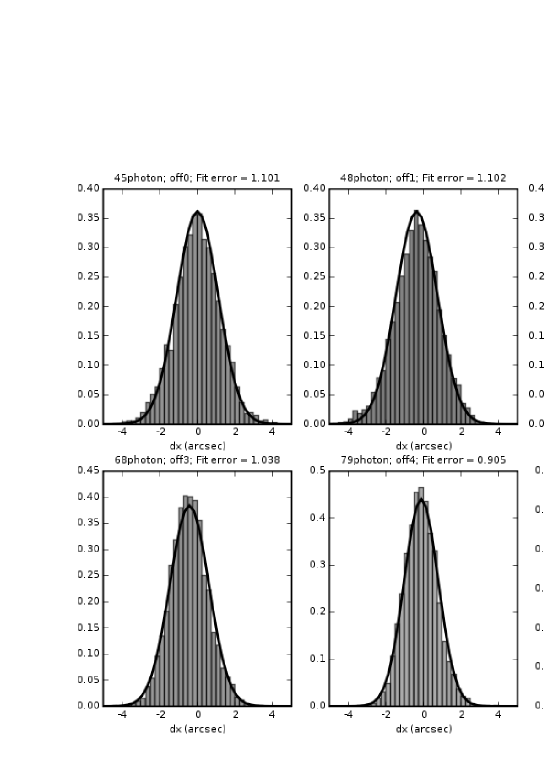
We tested this by simulating images where the real object position is known. We performed this simulation 5000 times for a given object position, and applied the PSF fit to each image. Fig. 2 shows the results for a range of positions starting over the bad columns and moving away from them. The histograms show the distance from the fitted position to the real position, and the solid line shows a Gaussian with a corresponding to the typical fit error. This shows both that the reported error is accurate, and that the fit performs well even when the object lies on the bad columns.
3 2. Prompt Positions
During the first snapshot after a GRB trigger, single pixel Photon Counting (PC) mode X-ray events with keV are telemetered to the ground via TDRSS. These Single Pixel Event Report (SPER) packages are distributed to the Swift XRT team every 390 seconds, an image is automatically extracted and the PSF fit (Section 1) is applied. Comparing positions thus produced with UVOT positions of optical counterparts, we find that the systematic uncertainty associated with the XRT boresight can be reduced to 2.9”, from the 3.5” deduced using a barycentric fit, thus these positions offer an improvement over the previous standard.
As SPER data are telemetered every 390 s, there are usually multiple deliveries per GRB. Experience shows that the position can be substantially improved between the first and second deliveries, but only minimally thereafter. Thus, either when the second SPER has been processed, or 9 minutes after the first SPER was received (if no second one has arrived), the position is distributed as a GCN Position (Update) Notice. This position is used in the initial GCN Circular prepared by the Swift team, which details the detection of the burst. All SPER positions are published online as soon as they are produced, at http://www.swift.ac.uk/spertable.php.
4 3. Enhanced Positions
As noted above, standard XRT positions have a systematic error of 3.5”, theoretically limiting the XRT’s position accuracy to this value. However, by determining the mapping between the XRT and UVOT detectors, we are able to use UVOT field astrometry to correct the XRT boresight, reducing the systematic to 1.5”. Note that this process does not require UVOT to detect the GRB, and works for 70% of Swift-detected bursts.
Full details of this process are given in Goad et al. (2007). A summary is: Use the PSF fit described above to determine the XRT detector position of a GRB, convert this into an equivalent UVOT detector position, and hence UVOT sky position. Align the UVOT field of view with the USNO-B1 catalogue to correct this position.
Because Swift does not remain perfectly steady, the XRT detector position of an object can drift during a snapshot, meaning we can only use times of simultaneous X-ray and UVOT data. Further, we limited the current version of our software to the UVOT filter, as it was for this that the map was determined. Data are thus split into overlaps, of simultaneous XRT PC mode data and UVOT -band data. The above process is applied to each overlap in turn, yielding one position per overlap. The weighted mean of these is then calculated, any individual positions more than from this are discarded and the mean is recalculated. Finally, the 1.5” systematic error arising from uncertainty in the UVOT-XRT mapping is added in quadrature to give the UVOT-enhanced XRT position. The position is immediately circulated to the XRT team, and posted online at http://www.swift.ac.uk/xrt_positions. When a position is first determined for a GRB, it is also distributed to the community in an automatically generated GCN circular (see Osborne et al. (2007)). Note that, if the UVOT-enhanced position is the first X-ray position found for a GRB, the automatic circular will not be sent. This is to give the XRT team a chance to check that the (probably faint) source is the afterglow. The position will still be posted online, and distributed via a circular when verified.
5 4. Future improvements
We are currently developing a second version of the UVOT-enhancement software. This code makes use of multiple UVOT filters (, and white), multiple Swift obsIDs, and an improved PSF fit algorithm which works in sky co-ordinates, using exposure maps to correct for bad columns, bad pixels and vignetting. This also allows for non-simultaneous X-ray and UVOT data to be used. Tests suggest that the new version reduces typical total error radii by 25–50%. Once testing is complete, the new version will take over live processing of GRBs – this will be announced via a GCN circular, hopefully in early 2008.
A parallel development is that, using the new version of the code, we are able to use the limited data products available immediately after a GRB trigger to UVOT-enhance the SPER data, combining the methods of Sections 2 and 3 in this paper. The improvement in SPER positions is less pronounced than with the full dataset, however we anticipate a reduction in error radius of 25% for a typical GRB.
References
- Burrows et al. (2005) D. Burrows, et al., SSRv 120, 165–195 (2005).
- Roming et al. (2005) P. Roming, et al., SSRv 120, 95–142 (2005).
- Cash (1978) W. Cash, ApJ 228, 939–947 (1978).
- Moretti et al. (2005) A. Moretti, et al., SPIE 5898, 348–356 (2005).
- Goad et al. (2007) M. Goad, et al., A&A 476, 1401–1409 (2007).
- Osborne et al. (2007) J. Osborne, et al., GCN Circ 6726 (2007).