Polarization–universal rejection filtering by ambichiral structures made of indefinite dielectric–magnetic materials
Abstract
An ambichiral structure comprising sheets of an anisotropic dielectric material rejects normally incident plane waves of one circular polarization (CP) state but not of the other CP state, in its fundamental Bragg regime. However, if the same structure is made of an dielectric–magnetic material with indefinite permittivity and permeability dyadics, it may function as a polarization–universal rejection filter because two of the four planewave components of the electromagnetic field phasors in each sheet are of the positive–phase–velocity type and two are of the negative–phase–velocity type.
pacs:
42.25.Bs, 42.25.Ja, 42.25.Lc, 42.72.-g. 42.79.Ci1 Introduction
This communication combines two topics of recent interest in electromagnetics: (i) the ambichiral structure that replicates the circular–polarization–sensitive filtering properties of cholesteric liquid crystals and chiral sculptured thin films, and (ii) the dielectric–magnetic material with indefinite permittivity dyadic and indefinite permeability dyadic.
The ambichiral structure is a structurally chiral pile of identical sheets that was conceived by Reusch [1] to transmit normally incident circularly polarized (CP) plane waves of one handedness but reflect CP plane waves of the other handedness, in a certain free–space–wavelength regime. This conceptualization influenced early theoretical research on the optical response characteristics of cholesteric liquid crystals [2, 3]. Following a systematic study in 2004, Reusch’s wavelength regime was identified as merely the first of a potentially infinite number of Bragg regimes [4]. For optical applications, since then the ambichiral structure has been experimentally realized using sculptured–thin–film technology [4, 5], and electro–optic versions have been suggested as electrically controlled CP filters [6, 7].
A real symmetric dyadic is said to be indefinite if some of its eigenvalues are positive but the remaining ones are negative. Artificial materials with indefinite permittivity and permeability dyadics came into prominence a few years ago, as such materials can exhibit negative refraction [8, 9]. Due to hyperbolic, instead of the usual elliptic, dispersion relations for planewave propagation in these materials [10, 11], several electromagnetic phenomenons — including surface–wave propagation [12], the Goos–Hänchen shift [13], and diffraction by surface–relief gratings [14, 15] — are exhibited by these materials in uncommon ways.
Motivated by these reports, an investigation was undertaken on the response to a normally incident plane wave of an ambichiral structure made of a dielectric–magnetic material with indefinite permittivity dyadic and indefinite permeability dyadic. True to expectation, the usual CP–filtering response of ambichiral structures was not obtained. Instead, a polarization–universal rejection response emerged, indicating thereby the existence of a polarization–universal bandgap [16, 17].
The plan of this communication is as follows. Section 2 contains a description of the ambichiral structure comprising orthorhombically anisotropic dielectric–magnetic sheets. Section 3 provides a succinct description of the boundary–value problem to be solved in order to determine the response characteristics of the ambichiral structure to a normally incident plane wave. Finally, numerical results are presented and discussed in Sec. 4.
A note on notation: Vectors are underlined and dyadics are double–underlined; the cartesian unit vectors are represented by , , and ; symbols for column vectors and matrixes are decorated by an overbar; and an time–dependence is implicit with as the angular frequency. The wavenumber, the wavelength, and the intrinsic impedance of free space are denoted by , , and , respectively, with and being the permeability and permittivity of free space.
2 Ambichiral Structure
The ambichiral structure is a structurally chiral pile of identical sheets, each of thickness and infinite transverse extent. The sheet, , occupies the region ; thus, the total thickness of the pile is . The sheets are not necessarily electrically thin, and the structure can therefore be considered as a 1–D photonic crystal [18, 19]. The halfspaces and are vacuous.
The permittivity and permeability dyadics of the sheet are chosen as
| (1) |
and
| (2) |
respectively. Both dyadics indicate anisotropy of the orthorhombic symmetry [20, 21]. The dyadic
| (3) |
indicates rotation about the axis by an angle with respect to the first sheet, with
| (4) |
the integer [4], the ratio an even integer, and the parameter for structural right–handedness and for structural left–handedness. The number of structural periods in the ambichiral structure is . The dyadic
| (5) |
indicates a tilt with respect to the plane by an angle .
3 Reflectances and Transmittances
Suppose that an arbitrarily polarized plane wave is normally incident on the ambichiral structure from the halfspace . In consequence, a reflected plane wave must exist in the same halfspace and a transmitted plane wave in the halfspace . The electric field phasors associated with the two plane waves in the halfspace are stated as
| (6) |
and
| (7) |
where . Likewise, the electric field phasor in the halfspace is represented as
| (8) |
Here, and are the known amplitudes of the left– and the right–CP (LCP & RCP) components of the incident plane wave; and are the unknown amplitudes of the reflected plane wave components; while and are the unknown amplitudes of the transmitted plane wave components.
The procedure to obtain the unknown reflection and transmission amplitudes involves the following 44 matrix relation [22, Chap. 10]:
| (9) |
The column vectors
| (10) |
and
| (11) |
derive from the tangential components of the electric and magnetic field phasors at the entry and the exit pupils, respectively. The 44 matrix [6]
| (12) |
encapsulating the planewave response of the entire ambichiral structure, contains the matrix
| (13) |
where
| (14) |
and the matrix [23]
| (15) |
involves
| (16) | |||
| (17) |
The reflection amplitudes and the transmission amplitudes can be computed for specified incidence amplitudes ( and ) by solving (9). Interest usually lies in determining the reflection and transmission coefficients entering the 22 matrixes in the following two relations:
| (24) | |||||
| (31) |
Both 22 matrixes are defined phenomenologically. The co–polarized transmission coefficients are denoted by and , and the cross–polarized ones by and ; and similarly for the reflection coefficients in (24). Reflectances and transmittances are denoted, e.g., as .
4 Numerical Results and Discussion
Let us assume that chosen material has negligible dispersion and dissipation over the free–space–wavelength range of interest, for the sake of simplicity. With the assumption that both the relative permittivity and the relative permeability dyadics are positive definite (i.e., and ), the fundamental Bragg regime of the ambichiral structure for normally incident plane waves has [4]
| (32) |
as its center–wavelength. This equation must also hold if both the relative permittivity and the relative permeability dyadics are negative definite (i.e., and ) [24, 25]. Even when the two dyadics are indefinite, we must ensure that the ambichiral structure is electromagnetically penetrable by normally incident plane waves, in general. Therefore let us impose the twin restrictions [14, 15]
| (33) |
The following four cases were chosen for numerical investigation:
-
•
PosDef: , , , .
-
•
NegDef: , , , .
-
•
Indef-1: , , , .
-
•
Indef-2: , , , .
All four cases satisfy the restrictions (33).
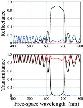
Computed spectrums of the eight reflectances and transmittances are shown in Fig. 1 for Case PosDef and the following structural parameters: , , , and nm. The fundamental Bragg regime in the figure as a high–reflectance feature for incident RCP plane waves is correctly predicted by (32). In the same free–space–wavelength regime, the transmission of incident LCP plane waves is very high. This CP–discriminatory phenomenon is called the circular Bragg phenomenon [22]. It occurs when the number of structural periods is sufficiently large, the sufficiency depending on the magnitude of the difference , which quantity may be called an effective local linear birefringence. The larger this birefringence in magnitude, the fewer the structural periods required to observe (and exploit) the circular Bragg phenomenon.
The reflectances and transmittances for RCP and LCP plane waves in Fig. 1 shall have to be interchanged if either
-
(i)
the sign of is changed, or
-
(ii)
the constitutive parameters for Case NegDef were to be used instead of those for Case PosDef.
The equivalence of the changes (i) and (ii) has been established analytically [25]: When the real parts of the permittivity and the permeability dyadics of a structurally chiral, magnetic–dielectric material are reversed in sign, the circular Bragg phenomenon displayed by the material in terms of reflectances and transmittances suffers a change which indicates that the structural handedness has been, in effect, reversed; additionally, the reflection and transmission coefficients suffer phase reversal. If both changes (i) and (ii) are required to occur simultaneously, they cancel out each other’s individual effects.
The situation changes completely for Case Indef-1. Spectrums of the four reflectances are plotted in Fig. 2, and those of the four transmittances in Fig. 3, for , , and nm. These spectrums are provided for ambichiral structures with 4, 6, 8, and 10 structural periods. When the number of structural periods is small, the responses to incident RCP and LCP plane waves are different. As the number of structural periods increases, the discrimination between the responses to CP plane waves of different handednesses decreases and virtually vanishes for in the two figures; concurrently, the transmittances become increasingly smaller.
Qualitatively similar conclusions were drawn from the spectrums of the reflectances and transmittances for Case Indef-2, for which reason those spectrums have not been provided here. Furthermore, for both Cases Indef-1 and Indef-2, the same conclusions emerged for all values of .
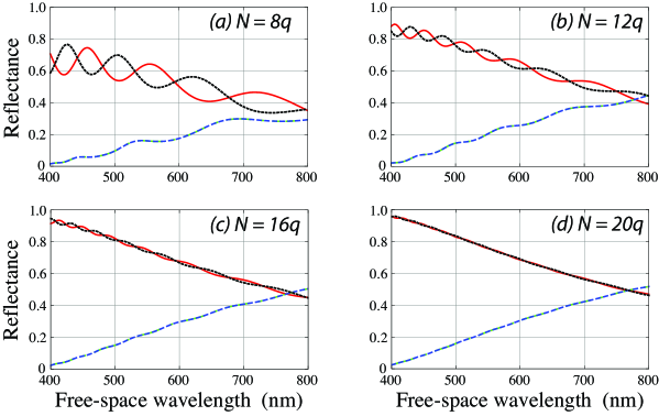
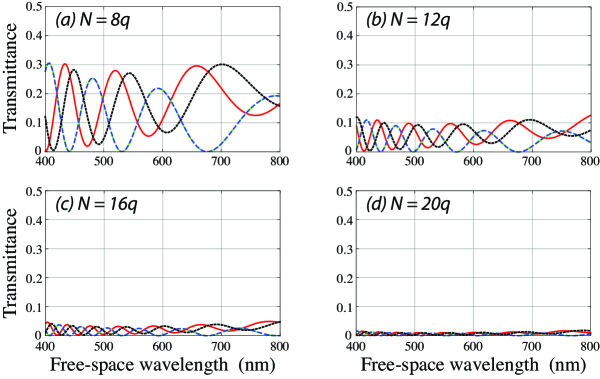
Taken together, the foregoing results offer the following significant result: an ambichiral structure, made of an dielectric–magnetic material with indefinite permittivity dyadic and indefinite permeability dyadic and containing a sufficiently large number of structural periods, can function as a polarization–universal rejection filter in its fundamental Bragg regime. Despite its structural chirality, an ambichiral structure thus does not necessarily function as a CP–discriminatory filter.
The polarization–universal rejection in Figs. 2 and 3 occurs over a much larger bandwidth than the CP–discriminatory rejection in Fig. 1. However, this observation is subject to modification when both dissipation and dispersion are considered.
In order to understand the different response characteristics for Cases PosDef and NegDef on the one hand and Cases Indef-1 and Indef-2 on the other, the electromagnetic field phasors inside the ambichiral structure have to be examined. Since all sheets are identical, except for a rotation about the axis, it suffices to examine the fields in the sheet labeled . In this sheet, the electromagnetic field phasors may be represented in terms of four plane waves as
| (34) |
and
| (35) |
where and are coefficients of expansion, and
| (36) |
The projection of the wave vector on the time–averaged Poynting vector of the planewave component associated with is either (i) positive if or (ii) negative if . Likewise, the projection of the wave vector on the time–averaged Poynting vector of the planewave component associated with is either (i) positive if or (ii) negative if .
For Case PosDef, all four planewave components inside each sheet are of the positive–phase–velocity (PPV) type. For Case NegDef, all four are of the negative–phase–velocity (NPV) type [26]. For either Case Indef-1 or Indef-2, two planewave components are of the NPV type and two of the PPV type. Both theory and experiment [1]–[7] show that CP–discriminatory rejection is possible in the fundamental Bragg regime when all four planewave components are of the PPV type. From the conjugate invariance of the frequency–domain Maxwell equations [27], it follows that CP–filtering must be possible in the fundamental Bragg regime when all four planewave components are of the NPV type. The polarization–universal rejection exemplified by Figs. 2 and 3 for Cases Indef-1 and Indef-2 — despite the pile of sheets being structurally chiral — must therefore be attributed to the fact that two planewave components out of four are of the PPV type and two of the NPV type.
Acknowledgments. This communication is dedicated to the fearless campaign of Iftikhar Choudhury, Aitzaz Ahsan and others in defense of democracy, justice, and constitutional rule of law.
References
References
- [1] Reusch E 1869 Untersuchung über Glimmercombinationen Ann. Phys. Lpz. 138 628–39
- [2] Joly G and Billard J 1982 Quelques champs électromagnétiques dans les piles de Reusch. II. Piles éclairées sous l’incidence normale par des ondes monochromatiques planes et uniformes J. Opt. (Paris) 13 227–38
- [3] Jacobs S D (ed) 1992 Selected Papers on Liquid Crystals for Optics (Bellingham, WA, USA: SPIE Press)
- [4] Hodgkinson I J, Lakhtakia A, Wu Q h, De Silva L and McCall M W 2004 Ambichiral, equichiral and finely chiral layered structures Opt. Commun. 239 353–8.
- [5] van Popta A C, Brett M J and Sit J C 2005 Double–handed circular Bragg phenomena in polygonal helix thin films J. Appl. Phys. 98 083517
- [6] Lakhtakia A 2006 Ambichiral, electro–optic, circular–polarization rejection filters: theory Phys. Lett. A 354 330–4
- [7] Dixit M and Lakhtakia A 2008 Electrically controlled Bragg resonances of an ambichiral electro–optic structure: oblique incidence Asian J. Phys. 17 at press; arXiv:0708.1638v1
- [8] Parazzoli C G, Greegor R B, Li K, Koltenbah B E C and Tanielian M 2003 Experimental verification and simulation of negative index of refraction using Snell’s law Phys. Rev. Lett. 90 107401
- [9] Smith D R, Kolinko P and Schurig D 2004 Negative refraction in indefinite media J. Opt. Soc. Am. B 21 1032–1043
- [10] Depine R A, Inchaussandague M E and Lakhtakia A 2006 Classification of dispersion equations for homogeneous dielectric–magnetic uniaxial materials J. Opt. Soc. Am. A 23 949–955
- [11] Luo H, Ren Z, Shu W and Li F 2007 Wave propagation in an anisotropic metamaterial with single–sheeted hyperboloid dispersion relation Appl. Phys. A 87 245–49
- [12] Yan W, Shen L, Ran L and Kong J A 2007 Surface modes at the interfaces between isotropic media and indefinite media J. Opt. Soc. Am. A 24 530–5
- [13] Xiang Y, Dai X and Wen S 2007 Negative and positive Goos–Hänchen shifts of a light beam transmitted from an indefinite medium slab Appl. Phys. A 87 285–90
- [14] Depine R A and Lakhtakia A 2005 Diffraction by a grating made of a uniaxial dielectric-magnetic medium exhibiting negative refraction New J. Phys. 7 158
- [15] Depine R A, Inchaussandague M E and Lakhtakia A 2006 Vector theory of diffraction by gratings made of a uniaxial dielectric–magnetic material exhibiting negative refraction J. Opt. Soc. Am. B 23 514–28
- [16] Sarkissian H, Zeldovich B Ya and Tabiryan N V 2006 Polarization–universal bandgap in periodically twisted nematics Opt. Lett. 31 1678–80.
- [17] Reyes J A and Lakhtakia A 2007 Optics of electrically controlled structurally chiral material with periodic transverse perturbation for polarization–universal bandgaps Opt. Commun. 270 51–7
- [18] Felbacq D and Zolla F 2003 Scattering theory of photonic crystals. In: Weiglhofer W S and Lakhtakia A (eds) 2003 Introduction to Complex Mediums for Optics and Electromagnetics (Bellingham, WA, USA: SPIE Press) pp. 365–393.
- [19] Haus J W 2004 Photonic bandgap structures. In: Lakhtakia A (ed) 2004 Nanometer Structures: Theory, Modeling, and Simulation (Bellingham, WA, USA: SPIE Press) pp. 45–106.
- [20] Lovett D R 1989 Tensor Properties of Crystals (Bristol, UK: Adam Hilger)
- [21] Mackay T G and Lakhtakia A 2008 Electromagnetic fields in linear bianisotropic mediums Prog. Opt. 51 121–208
- [22] Lakhtakia A and Messier R 2005 Sculptured Thin Films: Nanoengineered Morphology and Optics (Bellingham, WA, USA: SPIE Press)
- [23] Weiglhofer W S and Lakhtakia A 1993 Electromagnetic wave propagation in super-cholesteric liquid crystals parallel to the helical axis J. Phys. D: Appl. Phys. 26 2117–22
- [24] Lakhtakia A 2002 Reversal of circular Bragg phenomenon in ferrocholesteric materials with negative real permittivities and permeabilities Adv. Mater. 14 447–9
- [25] Lakhtakia A 2003 Handedness reversal of circular Bragg phenomenon due to negative real permittivity and permeability Opt. Express 11 716–22
- [26] Mackay T G and Lakhtakia A 2004 Plane waves with negative phase velocity in Faraday chiral mediums Phys. Rev. E 69 026602
- [27] Lakhtakia A 2004 Conjugation symmetry in linear electromagnetism in extension of materials with negative real permittivity and permeability scalars Microw. Opt. Technol. Lett. 40 160–1