A simple integrated single atom detector
Abstract
We present a reliable and robust integrated fluorescence detector capable of detecting single atoms. The detector consists of a tapered lensed single-mode fiber for precise delivery of excitation light and a multimode fiber to collect the fluorescence. Both are mounted in lithographically defined SU-8 holding structures on an atom chip. 87Rb atoms propagating freely in a magnetic guide are detected with an efficiency of up to 66% and a signal to noise ratio in excess of 100 is obtained for short integration times.
230.0040, 230.3120, 060.2340, 270.5290, 020.0020.
In an ideal background free fluorescence detector a single detected photon indicates the presence of atoms in the detection region. Moderate backgrounds can be tolerated if the atom remains localized, allowing to collect many fluorescence photons Grangier:SingleAtomEmission ; Diedrich:AntibunchingfromIon ; Blatt:IonTraps . Detection of moving particles with finite interaction time with the detector requires supreme background suppression to reach high detection efficiencies bondo:2006 . Cavities can be used to enhance the fluorescence or absorption signal Esslinger:AtomLaser ; AokiKimble:Microresonator ; ColombeReichel:BECinFibreCavityonChip ; Rempe:SingleAtomCavity ; teper:CavityonChip ; Haase:cavity ; trupke:Cavity but these detection schemes require active stabilization, increasing the complexity of the setup.
Our approach differs. We present here an integrated fluorescence detector which reaches high single atom detection efficiency without the need for either localization of the atoms or assistance of a cavity.
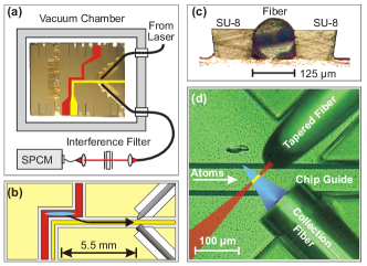
The detector consist of a single-mode tapered lensed excitation fiber and a multimode detection fiber (Fig.1(d)). The excitation fiber delivers resonant probe light to a focal spot of m diameter m above the wire defining the atom guide. The collection fiber (NA 0.275) collects of the fluorescence photons and guides them via a feed-through Abraham:TeflonFeedthrough out of the vacuum chamber. To eliminate background light and to protect the photon counter, the light passes through an interference filter before being directed to the single photon counting module (SPCM) for a total photon detection efficiency of (calculated from known loss channels and detector efficiencies). The fibers are arranged at to the guide and orthogonal to one another. In the absence of atoms, less than of the excitation light is scattered into the collection fiber, typically less than 10 photons per second in total. Due to the highly selective excitation and a matched collection region a total background of only counts per second (cps) is reached, dominated by the SPCM dark count rate of cps.
The detector is integrated on an atom chip groth:fabrication by mounting the fibers in lithographically defined trenches. These structures are fabricated from SU-8, an epoxy based photoresist which allows the production of thick structures with very smooth sidewalls FortPhys:2006 ; liu2005 . The SU-8 fabrication is fully compatible with our atom chip production process groth:fabrication . With a trench height of m and slightly undercut walls the fibers (m diameter) are clamped down onto the chip (Fig.1(c)). The trenches allow accurate and stable passive alignment of the fibers with a precision of a few ten nanometres. Temperature changes and gradients up to C resulted in no measurable misalignment of the fibers. Long term stability under experimental conditions of more than one year has been observed.
In our experiment we first load neutral 87Rb atoms into a magneto-optic trap (MOT). Once the MOT is saturated with atoms the trap is shifted close to the atom chip and the atoms are transferred into a magnetic trap generated by a Z-shaped wire on the atom chip (see Fig.1(a) and (b)) wildermuth:PRA ; Zimmermann:2007 . From the trap the atoms are transferred into a magnetic guide generated by a L-shaped wire in which the atoms expand towards the detection region according to their temperature (K for the data presented here). The current through this wire is adjusted to overlap the minimum of the guide potential with the focal spot where the atoms are excited.
One striking observation from measurements with this detector is that stray light effects on the guided atoms can be neglected. This is quite remarkable, because magnetic traps and guides are extremely sensitive to the presence of light close to resonance with the atomic transition. Scattering of a little more than a single photon is sufficient to pump the atom into a magnetically untrapped state, expelling it from the magnetic guide.
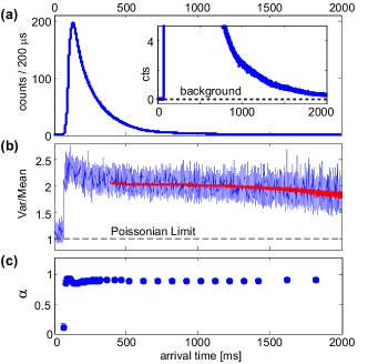
The atoms passing the detector creates a fluorescence signal shown in Fig.2(a) from which the atom density can be inferred if the number of counts per atom (cpa) is known. can be determined from the photon statistics. A coherent light source of constant mean photon number would create a Poisson distributed photon stream with variance equal to and hence . Because the atom number fluctuates according to a distribution Mandel’s formula RMP:MandelWolf has to be used to calculate the ratio of variance to mean to
| (1) |
where a Poissonian background noise source with mean intensity is included. Fig.2(b) shows the measured ratio for a thermal atomic ensemble which follows a Poissonian distribution . In the absence of atoms only a Poissonian background is measured. As soon as the atoms arrive at the detector the noise increases to . From these measurements the signal strength can be determined to cpa for an integration time of s, independent of atomic density (see Fig.2(c)).
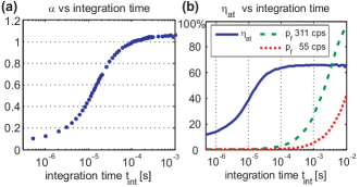
The single atom detection efficiency is given by , where is the probability of detecting zero photons when an atom is present in the detection region. The detection efficiency reaches 66% for s integration time. Background counts during this time lead to a false positive detection probability of . Fig.3(a) shows the signal strength as a function of the integration time, . At the same time, the mean number of background counts is a linear function of . For most applications it is therefore desirable to work at shorter integration times leading to high signal to noise ratios (SNR) (see Fig.3(b)). Defining an is reached at s (). At s the atom detection efficiency is with only false detection probability (Tab.1). The capability of detecting single atoms was independently verified by observing near-perfect anti-bunching of the photons with
The total number of photons scattered by the atoms before leaving the detection region can be independently obtained by measuring the ratio of fluorescence counts generated by illumination on the F=2F’=1 and the F=2F’=3 transitions. On the F=2F’=1 transition an atom scatters slightly more than one photon before being optically pumped into the other hyperfine ground state. This ratio indicates that each atom scatters photons on the employed cyclic F=2F’=3 transition before it leaves the detector. This confirms the above given photon detection efficiency of %. In addition the value of was confirmed by independent global atom number measurements using standard absorption imaging.
The efficiency of the detector is limited by the NA of the collection fiber, while the SNR is limited by the background. Exchanging the employed photon detector (Perkin-Elmer SPCM-AQR-12-FC) by a low noise model with a dark count rate cps a total background of cps can be achieved. Here would be reached already for s with and . Exchanging the collection fiber by a commercially available fiber of up to is expected and could be reached for s. Two detection fibres with a single atom detection efficiency beyond for s seems feasible. Such a system would reach . This allows true atom counting by transient count rate analysis bondo:2006 .
| single atom detection efficiency (NA 0.275 (0.53)) | |||
|---|---|---|---|
| s | s | s | |
| [cpa] | |||
We thank A. Haase, and M. Schwarz for help in the early stages of the experiment, and K.-H. Brenner, and I. Bar-Joseph for support in fabrication. We gratefully acknowledge financial support from the Landesstiftung Baden-Württemberg, the European Union (SCALA), and the Austrian Nano Initiative (PLATON).
References
- (1) B. Darquie, M. Jones, J. Dingjan, J. Beugnon, S. Bergamini, Y. Sortais, G. Messin, A. Browaeys, and P. Grangier, Science 309, 454 (2005).
- (2) F. Diedrich and H. Walther, Phys. Rev. Lett. 58, 203 (1987).
- (3) D. Leibfried, R. Blatt, C. Monroe, and D. Wineland, Rev. Mod. Phys. 75, 281 (2003).
- (4) T. Bondo, M. Hennrich, T. Legero, G. Rempe, and A. Kuhn, Opt. Commun. , ().
- (5) A. Öttl, S. Ritter, M. Köhl, and T. Esslinger, Phys. Rev. Lett. 95, 090404 (2005).
- (6) T. Aoki, B. Dayan, E. Wilcut, W. Bowen, A. Parkins, T. Kippenberg, K. Valhala, and H. Kimble, Nature 443, 671 (2006).
- (7) Y. Colombe, T. Steinmetz, G. Dubois, F. Linke, D. Hunger, and J. Reichel, Nature 450, 272 (2007).
- (8) P. Münstermann et al., Phys. Rev. Lett. 82, 3791 (1999).
- (9) I. Teper, Y.-J. Lin, and V. Vuletić, Phys. Rev. Lett. 97, 023002 (2006).
- (10) A. Haase, B. Hessmo, and J. Schmiedmayer, Opt. Lett. 31, 268 (2006).
- (11) M. Trupke, J. Goldwin, B. Darquié, G. Dutier, S. Eriksson, J. Ashmore, and E. A. Hinds, Phys. Rev. Lett. 99, 063601 (2007).
- (12) E. R. Abraham and E. A. Cornell, Appl. Opt. 37, 1762 (1998).
- (13) S. Groth, P. Kruger, S. Wildermuth, R. Folman, T. Fernholz, J. Schmiedmayer, D. Mahalu, and I. Bar-Joseph, Appl. Phys. Lett. 85, 2980 (2004).
- (14) M. Wilzbach, A. Haase, M. Schwarz, D. Heine, K. Wicker, S. G. X. Liu, K.-H. Brenner, T. Fernholz, B. Hessmo, and J. Schmiedmayer, Fortschr. Phys. , ().
- (15) X. Liu, K.-H. Brenner, M. Wilzbach, M. Schwarz, T. Fernholz, and J. Schmiedmayer, Appl. Opt. 44, 6857 (2005).
- (16) S. Wildermuth, P. Krüger, C. Becker, M. Brajdic, S. Haupt, A. Kasper, R. Folman, and J. Schmiedmayer, Phys. Rev. A 69, 030901 (2004).
- (17) J. Fortágh and C. Zimmermann, Rev. Mod. Phys. 79, 235 (2007).
- (18) L. Mandel and E. Wolf, Rev. Mod. Phys. 37, 231 (1965). To calculate the mean and variance we use , where is the probability to have atoms in the considered time interval. Each atom emits on average photons.