Static and dynamic properties of , , and ferromagnetic tunnel Josephson Junctions
Abstract
We present experimental studies of static and dynamic properties of , and superconductor-insulator-ferromagnet-superconductor (SIFS) Josephson junctions of small and intermediate length. In the underdamped limit these junctions exhibit a rich dynamical behavior such as resonant steps on the current-voltage characteristics. Varying the experimental conditions, zero field steps, Fiske steps and Shapiro steps are observed with a high resolution. A strong signature of the Josephson junction is demonstrated by measuring the critical current as a function of two components (, ) of an in-plane magnetic field. The experimental observation of a half-integer zero field step in SIFS junctions is presented.
pacs:
74.50.+r; 05.45.Yv; 74.81.Fa; 85.25.CpI Introduction
The interplay between superconductivity and ferromagnetism has been studied during many decades Buzdin (2005), but only during the last few years considerable results have been achieved regarding the experimental realization of and Josephson junctions (JJs) using superconductor-ferromagnet (SF) multilayers. In such structures the Cooper pair wave function penetrates into the ferromagnet in the form of damped oscillations.Fulde and Ferrell (1964); Larkin and Ovchinnikov (1965) If the thickness of the ferromagnetic barrier is of the order of half the oscillation period, the superconducting wave function changes its sign, i.e., shifts its phase by while crossing the ferromagnet. In SFS or SIFS JJs this leads to a negative critical current and the current-phase relation reads with . Such a JJ is called “ JJ”, because it has in the ground state, i.e., when no bias current is applied. In this context, conventional JJs are called “ JJ” because they have a current-phase relation of with and the ground state phase . In experiment a single JJ and a single JJ are indistinguishable, as one can only determine because on current-voltage characteristics we have both , so that the sign of is invisible. During the last years several experiments showed a change in the sign of as a function of temperatureRyazanov et al. (2001a) or of the thickness of the ferromagnetic barrierBlum et al. (2002); Kontos et al. (2002); Oboznov et al. (2006); Weides et al. (2006a) . The signatures of JJs were also demonstrated by embedding SFS JJs into superconducting loops.Ryazanov et al. (2001b); Guichard et al. (2003); Bauer et al. (2004) JJs are supposed to improve the performance of various classical and quantum electronic circuits, e.g., they can be used in RSFQ logics to self bias the circuit and to reduce the number of bias resistorsOrtlepp et al. (2006) and inductancesUstinov and Kaplunenko (2003) or to design environmentally decoupled “quiet” flux qubits.Ioffe et al. (1999); Yamashita et al. (2005) Depending on the target parameters, SFS or SIFS JJs are used. An advantage of SIFS JJs is that their resistance-area product can be tuned over orders of magnitude by varying the thickness of the insulating barrier. A high product facilitates voltage readout and allows to observe dynamic behavior of the junction due to low damping. Thus, these junctions can be used not only as phase batteries but also as active switching elements in superconducting electronic circuits. By contrast, SFS JJs have a small product and are always in the overdamped limit.
An intentionally made symmetric SIFS JJ with two reference junctions was demonstrated recently.Weides et al. (2006b) Before that, JJs were realized by utilizing d-wave superconductorsTsuei and Kirtley (2000); Smilde et al. (2002); Van Harlingen (1995); Hilgenkamp et al. (2003) or by chance using SFS JJs.Della Rocca et al. (2005); Frolov et al. (2006) These SFS JJs had a very small product, an accidentally achieved to phase transition, and no reference junctions were available. The SIFS JJ of Ref. Weides et al., 2006b consisted of and parts with equal critical current densities, as can be concluded from the measurements of the reference junctions. This JJ had a high characteristic voltage making direct transport measurements possible. The JJs could be driven into the underdamped regime by decreasing the temperature below 4.2 K. Tuning the temperature, the same absolute critical current densities in both parts were achieved. In this symmetric case the ground state of the system consists of a spontaneously formed vortex of supercurrent circulating around the boundary. This supercurrent corresponds to a local magnetic flux , where is the magnetic flux quantum. In the case of a very long JJ the flux , and thus the localized magnetic field is called semifluxon.Goldobin et al. (2002) A SIFS JJ is a promising system to study the physics of semifluxons. One can also use -0 SIFS JJs to design semifluxon molecule qubits.Kato and Imada (1997); Goldobin et al. (2005) No restrictions in topography, low damping and good reproducibility make the phase modulated SIFS JJs good candidates for future logic elements.
In this paper we study dynamic and static properties of SIFS JJs and of the corresponding reference and JJs. The junction parameters allow to investigate the overdamped as well as the underdamped regime by varying the temperature between and . Various resonant steps on the current-voltage characteristics are observed. Special attention is paid to the signatures of the - boundary.
II Experimental results
II.1 Samples
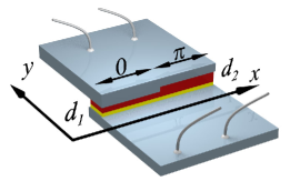
Our SIFS Josephson junctions are fabricated in overlap geometry using Nb/Al-Al2O3/Ni60Cu40/Nb technology.Weides et al. (2007a, 2006c) Varying the thickness of the ferromagnetic barrier, Josephson junctions with and ground states are obtained.Weides et al. (2006a) To fabricate SIFS Josephson junctions, the ferromagnetic layer was selectively etched along one half of the junction. In this way one half of the junction has a F-layer thickness and, if taken separately, would be in a ground state with a phase drop of zero, while the other half of the junction has a F-layer thickness and, if taken separately, would be in a ground state with a phase drop of .Weides et al. (2006b) A schematic drawing of such a long JJ (LJJ) is shown in Fig. 1. The lengths of the and parts are equal with a lithographic accuracy of less than . For each JJ two reference junctions (one JJ with and one JJ with ), having the same length as the 0- JJ, are fabricated in the same run. We assume that the critical current densities and are the same in the reference and in the 0- JJs, so that the reference JJs can indeed be used to obtain information about the 0 and parts of a 0- JJ.
In this paper we present experimental data for two sets of samples. Each set is situated on a separate chip (chip and chip ) and contains three JJs: a JJ, a 0 JJ and a JJ. The thickness of the insulating barrier is thinner on chip , resulting in higher critical current densities in comparison with chip . The junction parameters are summarized in Tab. 1. The critical current densities of the reference junctions are obtained by measuring their - characteristics (IVCs), while for the JJs only the average value is quoted. is used to calculate the normalized lengths of the JJs. Actually, this value is a simplified picture to facilitate the calculations. It is different from the measured critical current density in a JJ, i.e., from at , a situation when the critical currents in both halves are partially or totally canceling each other. While calculating the idle region corrections are taken into account.Wallraff (2001); Monaco et al. (1995)
| id @ (K) | () | () | () | () | |
|---|---|---|---|---|---|
| - @ 4.2 K | 2.1 | 0.72 | 330 | 30 | 50 |
| - @ 4.2 K | 1.5 | 0.62 | 330 | 30 | 50 |
| - @ 4.2 K | 1.8 | 0.67 | 330 | 30 | 50 |
| - @ 0.34 K | 13.4 | 3.1 | 500 | 12.5 | 10 |
| - @ 0.34 K | 4.5 | 1.8 | 500 | 12.5 | 10 |
| - @ 0.34 K | 9.0 | 2.5 | 500 | 12.5 | 10 |
Note that early measurements using sample set were already published.Weides et al. (2006b) The measurements reported here were done at least eight months later. It turned out that some parameters, e.g., values, slightly changed with time presumable due to the clustering in the F-layer and degradation of the interfaces.
The measurements are carried out in a standard 4He- or 3He cryostat. The 4He cryostat can be evacuated so that temperatures from down to are reached. Using the 3He cryostat, temperatures between and are accessible. In both measurement setups a cryoperm shield is placed around the sample to shield it from the earth magnetic field or stray fields.
II.2 Static properties
We study the static properties of sample set by measuring the dependences of the critical current on magnetic field . The junctions are cooled down in the absence of magnetic field or bias current to provide a flux free state. Magnetic fields with both and components can be applied in the plane of the junctions, see Fig. 1. The and dependences of the and reference junctions have almost perfect Fraunhofer patterns (not shown) indicating a state without trapped flux. The maxima of the curves reveal a small offset from zero magnetic field probably due to a weak net magnetization of the ferromagnet. Applying only , the field value at the first minimum of dependence is times larger than the corresponding value on the curve. This corresponds to the ratio between the length and the width of the Josephson junctions on chip ().
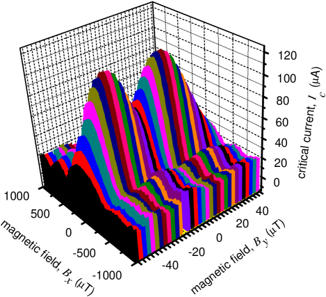
Fig. 2 shows the dependence of the junction of set 1. Applying a magnetic field in direction results in an almost perfect Fraunhofer pattern, indicating that no parasitic flux is trapped in the junction or its electrodes. Applying magnetic field in direction a well pronounced minimum around zero field is visible. This minimum is a characteristic feature of a Josephson junction.Wollman et al. (1993); Smilde et al. (2002); Kirtley et al. (1997) Thus, Fig. 2 leaves no doubts that the observed behavior is due to the step in the ferromagnetic barrier and not due to some other reasons. The normalized junction length is calculated as at . In contrast to earlier investigations of this sampleWeides et al. (2006b) the idle region correctionsWallraff (2001); Monaco et al. (1995) are now taken into account. Although the junction is short in terms of (), in the central minimum on the dependence does not reach zero as it should be for a short JJGoldobin et al. (2004a), most probably because at . The asymmetry factor is estimated as , i.e., the critical current densities in the and parts differ by about 30 . For such an asymmetry the ground state is fluxless Weides et al. (2007b); Bulaevskii et al. (1978).
II.3 Dynamic properties
We study the dynamic properties by measuring current-voltage (-) characteristics (IVC). The IVC directly reveals the relationship between the average flux velocity , which is proportional to the measured dc voltage , and the driving force, which is proportional to the bias current . To observe dynamics, the junction under examination has to be in the underdamped regime. This is typically the case for temperatures below . At none of our samples is underdamped. By decreasing the temperature all junctions become underdamped.
II.3.1 Half-integer ZFSs in junctions
Fiske steps (FSs) appear on the IVCs of JJs in magnetic field when the parameter is relatively small. Physically, a Fiske resonance is the synchronization between a moving Josephson vortex chain and a standing electromagnetic wave in the JJ. The resonance number determines the number of wave lengths of the standing wave. The asymptotic voltage of the -th Fiske step is given by
| (1) |
where is the Swihart velocity. By contrast, if IVC measurements are carried out in the absence of magnetic field or microwaves one can also observe steps on the IVC of a LJJ. These steps, naturally called zero field steps (ZFSs), have a voltage spacing twice larger than the one of Fiske steps.
The origin of ZFSs is different from Fiske steps. A ZFS with index corresponds to fluxons moving inside the JJ driven by the bias current. When one of the fluxons reaches the JJ boundary, it reflects back as an antifluxon, thus transferring a flux through the boundary per seconds — the time needed for a fluxon to shuttle once back and forth along the JJ. Thus the voltage across the junction is given by
| (2) |
If, in this mode, one increases the bias current, the fluxons move faster and eventually almost reach the Swihart velocity . Thus, the voltage spacing between the ZFSs is , i.e., twice larger than for Fiske steps.
These expectations are met in our experiments in the underdamped limit with the and junction of sample set . The observed ZFSs have a voltage spacing which is exactly two times larger than the one of Fiske steps (not shown).
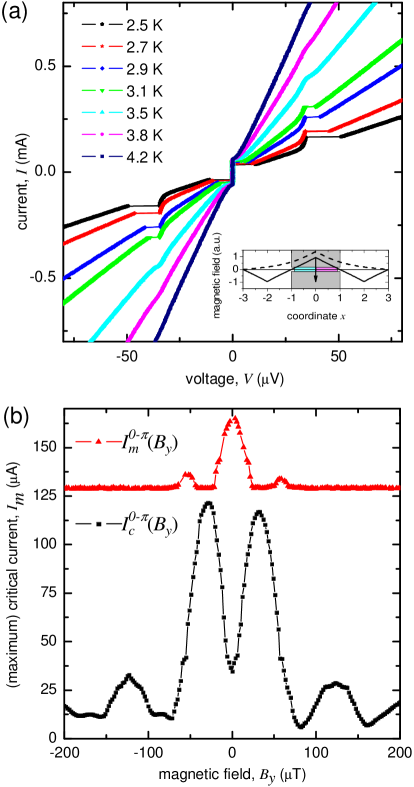
In the case of the junction the first ZFS emerges at exactly half of the usual ZFS spacing, i.e., exactly at the same voltage as the first Fiske step, according to the earlier predictionsStefanakis (2002); Lazarides (2004) and to experiments on JJs of other types.Goldobin et al. (2004a) Fig. 3 (a) shows IVCs of the JJ - measured at different and at . At , which is exactly the observed value of the Fiske step voltage spacing in this sample, a step is emerging for . The step appears due to the flipping of a fractional vortex.Goldobin et al. (2004a) At zero bias current, for our JJ length and asymmetry, the ground state of the system is a flat phase state (fluxless). As soon as a uniform bias current is applied, a fractional flux (Josephson vortex) localized at the 0- boundary and carrying a bias current dependent flux appears.Goldobin et al. (2003) Since the junction has a finite length, the interaction of this vortex with the boundary can be treated as the interaction of the vortex with an antivortex (image) situated outside the junction at the same distance from the edge. There are two such images, one behind the left and one behind the right edge of the JJ, see the inset of Fig. 3 (a). The bias current exerts a Lorenz force which tries to collide the vortex with one of the images. If the bias is large enough, both the vortex and the image vortex flip, changing polarity and exchanging one flux quantum, which, in fact, is passing through the JJ boundary. Then a similar process takes place between the fractional vortex (now of negative polarity) and another image, so one passes through the other JJ boundary. Assuming that the maximum velocity of flux transfer is , we calculate that the asymptotic voltage is exactly equal to the voltage of the first Fiske step.
In order to show that the observed step is indeed a ZFS, the maximum current of this step versus magnetic field is measured, see Fig. 3 (b). The has a maximum in zero field and is decreasing with applied magnetic field — which is the typical behavior of a ZFS. The background value of corresponds to the current on the McCumber branch at below which the step cannot be suppressed in principle. Fig. 3 (b) additionally shows the curve measured at the same temperature of for comparison. The minimum around , typical for 0- JJs, is visible. Note that the amplitude of is higher than in Fig. 2 as the temperature is lower. The next ZFS emerges at () and corresponds to one additional fluxon moving inside the JJ. Comparable measurements are performed for sample set and show similar results (not shown).
Up to now half-integer ZFS have been observed only in artificial junctions.Goldobin et al. (2004a) To our knowledge, here we report on the first measurements of a half-integer ZFS in SIFS junctions.
II.3.2 Fiske steps
The junctions of sample set are prepared in a flux free state. By applying a magnetic field various Fiske steps were observed on the IVCs. Data presented below are taken at (underdamped regime) for sample -.
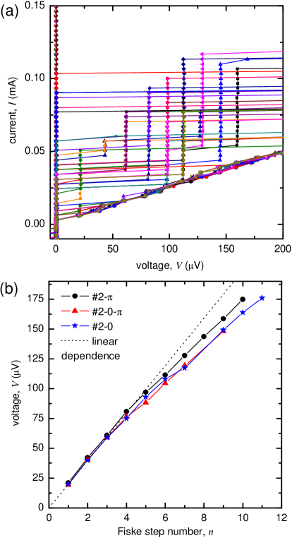
The low voltage part of several IVCs of junction - at different magnetic fields in the range is shown in Fig. 4 (a). Nine Fiske steps are observed with a high resolution. Similar Fiske step measurements were also carried out for the samples - and - (not shown). To summarize these measurements, in Fig. 4 (b) we plot the voltage positions of Fiske steps versus step number for all three samples. The first four Fiske steps have an almost equidistant voltage spacing. For higher Fiske steps the voltage spacing between adjacent Fiske steps shrinks with increasing step number. Thus the dispersion relation of electromagnetic waves in the junctions is not linear. A possible explanation might be the layout of the junctions and the fabrication process: inhomogeneities in the junction may result in a decreasing voltage spacing of resonant steps on the IVC, compare with Ref. Barbara et al., 1996. Local inhomogeneities are, e.g., non ideal junction boundaries, where the profile of the critical current does not sharply go to zero but is smeared out. This is the case if the junction is surrounded by a large idle region, which is true for our samples.
As visible in Fig. 4 (b), the Fiske step voltage spacing of the junction shows the smallest deviation from an equidistant voltage spacing, indicating a better homogeneity as compared to the and junction. Note that the F-layer of the last two junctions (or parts of it) is etched during the fabrication process. The etching might cause additional inhomogeneities. This topic was already discussed in the literature as material dispersion Hermon et al. (1994); Lee and Barfknecht (1992). The authors had shown that due to idle region effects or a frequency dependent magnetic penetration depth, summarized as material dispersion, the dispersion relation of electromagnetic waves in JJs is not linear.
Another explanation is that is more sensitive to variations in (roughness) than because and are chosen so that
| (3) |
see Fig. 1 of Ref. Weides et al., 2006a.
To calculate the capacitance of the junctions the voltage spacing of the first four Fiske steps is used. The capacitance is estimated as which also includes idle region effects. From geometrical considerations the contributions of the idle region () and the naked junction () to the capacitance can be estimated. The respective capacitance is calculated as , being the length and being the width of the junction or idle region, see Tab. 1.
Taking , and and , the idle region has a capacitance of . The Swihart velocity in the naked junction is calculated as with being the vacuum speed of light and being the inductance (per square) of the junction electrodes, resulting in .
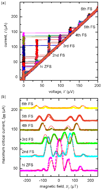
Comparable Fiske step measurements are performed for sample set . The low voltage part of several IVCs of sample - at is shown in Fig. 5 (a). The magnetic field is varied between . In Fig. 5 (b) the dependences of the maximum current of the Fiske steps on magnetic field are presented. Note that every odd FS is mixed with a half-integer ZFS, thus resulting in a finite step height even for . Our experimental data reproduce theoretical predictions rather wellNappi et al. (2006). The authors used a perturbative scheme to calculate phase dynamics and the resulting resonances appearing on the IVC of JJs with an arbitrary number of singularities. As realized in our samples they considered the flat phase regime where no spontaneous flux is occurring in the ground state of a JJ with finite length. Using the expressions number (27) and (28) from Ref. Nappi et al., 2006 with the respective parameters of our samples we are able to compare experiment and theory, see solid lines in Fig. 5 (b). The analytical calculations are performed in normalized units and converted to physical units by a fitting procedure: The -axis is adjusted by superimposing the first minimum of the curve of the half-integer ZFS in experiment and theory. This conversion scheme is used for all six measurements. The -axes are adjusted separately using a similar procedure. We find a very good agreement between the analytical predictions and the experimental data. The spacing of the minima, the height of the maxima as well as the overall shape of the measurements are reproduced by theoryNappi et al. (2006).
As it was pointed out each odd step is a mixture of Fiske and half-integer ZFS. The amplitude of the 3rd step is above the background level due to its ZFS contribution. For the 5th FS, coincides with the background level as the ZFS contribution is vanishing.
II.3.3 Shapiro steps
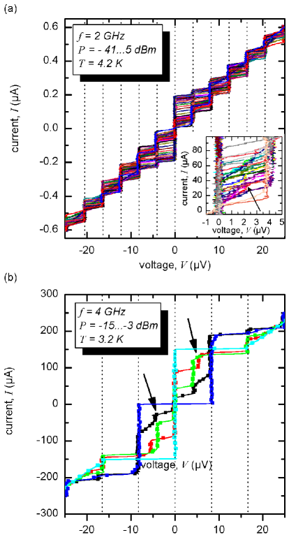
Shapiro step measurements are carried out for sample set . IVCs are measured at different temperatures in the presence of applied microwaves. Constant voltage steps appear on the IVC due to the synchronization of Josephson oscillations to the applied excitation. As an example, Shapiro step measurements for sample - at and are shown in Fig. 6. Microwave frequencies of and are applied. In both cases resonant steps which fulfill the condition ( and , respectively) are observed. Additionally, half-integer Shapiro steps are visible which have a voltage spacing of ). They are weakly pronounced for at , see inset of Fig. 6 (a). At the junction is in the overdamped regime. These experimental conditions are chosen to avoid chaotic dynamics. With decreasing temperature and increasing frequency the half-integer Shapiro steps become more pronounced, see Fig. 6 (b).
The occurrence of half-integer Shapiro steps reminds one of the ongoing discussion about non-sinusoidal current-phase relations in junctions. As already described a to transition can be achieved in SFS or SIFS junctions as a function of temperature Ryazanov et al. (2001a) or ferromagnetic barrier thickness.Kontos et al. (2002) As close to the transition the first order Josephson supercurrent vanishes, the observation of a component seems possible in the transition region. Half-integer Shapiro steps have been reported for SFS junctions in the vicinity of the minimum of .Sellier et al. (2004) The authors attributed these steps to the component. In other experiments Frolov et al. (2006) half-integer Shapiro steps are explained with a non-uniform critical current density, without the need of an intrinsic component. Thus, the conclusive explanation of the origin of half-integer Shapiro steps is still an open problem.
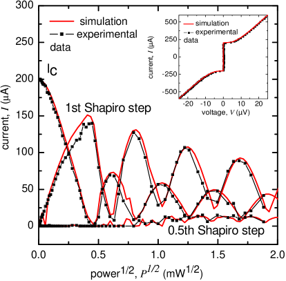
In order to examine whether our half-integer Shapiro steps are due to a non sinusoidal current-phase relation, Shapiro step measurements for different excitation amplitudes are carried out. As an example, the experimental parameters and of sample - at are obtained from experiment and are used for simulations. Current-voltage characteristics can be simulated according to the RCSJ-model, see inset of Fig. 7. A current-phase-relation is used with an additional term, which can be weighted by a factor of . Shapiro steps are measured in experiment by radiating microwaves with a frequency of . As a first try simulations are performed without taking the component into account (). The height of the Shapiro steps is extracted from experimental data and from simulations. As expected the respective step heights are proportional to the Bessel functions. In Fig. 7 we compare the height of the Shapiro steps with as a function of applied microwave power, obtained in experiment and simulation. One can see a perfect quantitative agreement. Although the component is not taken into account, the half-integer Shapiro step appears in the simulations and reproduces the experimental data perfectly well. This is a result of a finite capacitance, i.e., .
The simulations are repeated taking the component into account (not shown). As long as the second harmonic is small (), the experimental data are reproduced by the numerical simulations. As soon as the second harmonic contribution is higher than , the simulations deviate significantly from the experimental data. These data confirm our assumption, that the half-integer Shapiro steps are not due to a contribution. Half-integer Shapiro steps are also observed for the samples - and - (not shown). The experimental data are reproduced in simulations without the need of a component, too.
Nevertheless, half-integer Shapiro steps are observed here in systems in which the component does not play a dominant role as the component is not suppressed. In this case the half-integer Shapiro step is a subharmonic step and not attributed to a double Josephson frequency.
III Conclusions
We experimentally studied the static and dynamic properties of , and SIFS Josephson junctions using two sets of samples: being in the short junction limit, and having an intermediate junction length. All samples can be made underdamped at sufficiently low temperatures below . Fiske steps, zero field steps and Shapiro steps were observed on the - characteristics. The dynamic properties of 0 and SIFS junctions are qualitatively similar to standard SIS junctions.
We have observed half-integer Shapiro steps on the current-voltage characteristics of , and Josephson junctions, which does not necessarily imply the presence of the second harmonic in the current-phase relation, but may be present due to the finite capacitance of the Josephson junctions. The analysis of a short overdamped JJ in the framework of the RSJ model, confirms this picture.
Half-integer zero field steps were observed on the - characteristics of Josephson junctions. The dependences for several Fiske and zero field steps were measured. To our knowledge, this is the first time when a half-integer zero field step is reported for “natural” 0- JJs, as opposed to “artificial” 0- JJs with current injectors for which half-integer zero field steps were observed before.Goldobin et al. (2004a)
Thus, SIFS , and JJ technology can already be used to fabricate more complex superconducting electronic devices combining the dynamics of fluxons and semifluxons, e.g., using RSFQ readout for semifluxon bits/qubits or ballistic fluxon readout.Goldobin et al. (2004b); Kidiyarova-Shevchenko et al. (2007)
Acknowledgements.
We thank T. Gaber for useful discussions. Financial support by the the Studienstiftung des Deutschen Volkes (J. Pfeiffer), by the Evangelisches Studienwerk e.V. Villigst (M. Kemmler) and by the DFG (project WE 4359/1-1, project SFB/TRR 21 and GO 1106/1-1) is gratefully acknowledged.References
- Buzdin (2005) A. I. Buzdin, Rev. Mod. Phys. 77, 935 (2005).
- Fulde and Ferrell (1964) P. Fulde and R. A. Ferrell, Phys. Rev. 550, 135 (1964).
- Larkin and Ovchinnikov (1965) A. Larkin and Y. N. Ovchinnikov, Sov. Phys. JETP 20, 762 (1965).
- Ryazanov et al. (2001a) V. V. Ryazanov, V. A. Oboznov, A. Y. Rusanov, A. V. Veretennikov, A. A. Golubov, and J. Aarts, Phys. Rev. Lett. 86, 2427 (2001a).
- Blum et al. (2002) Y. Blum, A. Tsukernik, M. Karpovski, and A. Palevski, Phys. Rev. Lett. 89, 187004 (2002).
- Kontos et al. (2002) T. Kontos, M. Aprili, J. Lesueur, F. Genêt, B. Stephanidis, and R. Boursier, Phys. Rev. Lett. 89, 137007 (2002).
- Oboznov et al. (2006) V. A. Oboznov, V. V. Bol’ginov, A. K. Feofanov, V. V. Ryazanov, and A. I. Buzdin, Phys. Rev. Lett. 96, 197003 (2006).
- Weides et al. (2006a) M. Weides, M. Kemmler, E. Goldobin, D. Koelle, R. Kleiner, H. Kohlstedt, and A. Buzdin, Appl. Phys. Lett. 89, 122511 (2006a).
- Ryazanov et al. (2001b) V. V. Ryazanov, V. A. Oboznov, A. V. Veretennikov, and A. Y. Rusanov, Phys. Rev. B 65, 020501 (2001b).
- Guichard et al. (2003) W. Guichard, M. Aprili, O. Bourgeois, T. Kontos, J. Lesueur, and P. Gandit, Phys. Rev. Lett. 90, 167001 (2003).
- Bauer et al. (2004) A. Bauer, J. Bentner, M. Aprili, M. L. Della-Rocca, M. Reinwald, W. Wegscheider, and C. Strunk, Phys. Rev. Lett. 92, 217001 (2004).
- Ortlepp et al. (2006) T. Ortlepp, Ariando, O. Mielke, C. J. M. Verwijs, K. F. K. Foo, H. Rogalla, F. H. Uhlmann, and H. Hilgenkamp, Science 312, 1495 (2006).
- Ustinov and Kaplunenko (2003) A. V. Ustinov and V. K. Kaplunenko, J. Appl. Phys. 94, 5405 (2003).
- Ioffe et al. (1999) L. B. Ioffe, V. B. Geshkenbein, M. V. Feigel man, A. L. Fauche re, and G. Blatter, Nature (London) 398, 679 (1999).
- Yamashita et al. (2005) T. Yamashita, K. Tanikawa, S. Takahashi, and S. Maekawa, Phys. Rev. Lett. 95, 097001 (2005).
- Weides et al. (2006b) M. Weides, M. Kemmler, E. Goldobin, H. Kohlstedt, R. Waser, D. Koelle, and R. Kleiner, Phys. Rev. Lett. 97, 247001 (2006b).
- Tsuei and Kirtley (2000) C. C. Tsuei and J. R. Kirtley, Rev. Mod. Phys. 72, 969 (2000).
- Smilde et al. (2002) H.-J. H. Smilde, Ariando, D. H. A. Blank, G. J. Gerritsma, H. Hilgenkamp, and H. Rogalla, Phys. Rev. Lett. 88, 057004 (2002).
- Van Harlingen (1995) D. J. Van Harlingen, Rev. Mod. Phys. 67, 515 (1995).
- Hilgenkamp et al. (2003) H. Hilgenkamp, Ariando, H.-J. H. Smilde, D. H. A. Blank, G. Rijnders, H. Rogalla, J. R. Kirtley, and C. C. Tsuei, Nature (London) 422, 50 (2003).
- Della Rocca et al. (2005) M. L. Della Rocca, M. Aprili, T. Kontos, A. Gomez, and P. Spathis, Phys. Rev. Lett. 94, 197003 (2005).
- Frolov et al. (2006) S. M. Frolov, D. J. Van Harlingen, V. V. Bolginov, V. A. Oboznov, and V. V. Ryazanov, Phys. Rev. B 74, 020503(R) (2006).
- Goldobin et al. (2002) E. Goldobin, D. Koelle, and R. Kleiner, Phys. Rev. B 66, 100508(R) (2002).
- Kato and Imada (1997) T. Kato and M. Imada, J. Phys. Soc. Jpn. 66, 1445 (1997).
- Goldobin et al. (2005) E. Goldobin, K. Vogel, O. Crasser, R. Walser, W. P. Schleich, D. Koelle, and R. Kleiner, Phys. Rev. B 72, 054527 (2005).
- Weides et al. (2007a) M. Weides, C. Schindler, and H. Kohlstedt, J. Appl. Phys. 101, 063902 (2007a).
- Weides et al. (2006c) M. Weides, K. Tillmann, and H. Kohlstedt, Physica C 437–438, 349 (2006c).
- Wallraff (2001) A. Wallraff, Ph.D. thesis, Erlangen (2001), URL http://fluxon.physik.uni-erlangen.de.
- Monaco et al. (1995) R. Monaco, G. Costabile, and N. Martucciello, J. Appl. Phys. 77, 2073 (1995).
- Wollman et al. (1993) D. A. Wollman, D. J. Van Harlingen, W. C. Lee, D. M. Ginsberg, and A. J. Leggett, Phys. Rev. Lett. 71, 2134 (1993).
- Kirtley et al. (1997) J. R. Kirtley, K. A. Moler, and D. J. Scalapino, Phys. Rev. B 56, 886 (1997).
- Goldobin et al. (2004a) E. Goldobin, A. Sterck, T. Gaber, D. Koelle, and R. Kleiner, Phys. Rev. Lett. 92, 057005 (2004a).
- Weides et al. (2007b) M. Weides, J. Pfeiffer, M. Kemmler, D. Koelle, R. Kleiner, and E. Goldobin, in preparation (2007b).
- Bulaevskii et al. (1978) L. N. Bulaevskii, V. V. Kuzii, and A. A. Sobyanin, Solid State Commun. 25, 1053 (1978).
- Stefanakis (2002) N. Stefanakis, Phys. Rev. B 66, 214524 (2002).
- Lazarides (2004) N. Lazarides, Phys. Rev. B 69, 212501 (2004).
- Goldobin et al. (2003) E. Goldobin, D. Koelle, and R. Kleiner, Phys. Rev. B 67, 224515 (2003).
- Barbara et al. (1996) P. Barbara, R. Monaco, and A. V. Ustinov, J. Appl. Phys. 79, 327 (1996).
- Hermon et al. (1994) Z. Hermon, A. Stern, and E. Ben-Jacob, Phys. Rev. B 49, 9757 (1994).
- Lee and Barfknecht (1992) G. S. Lee and A. T. Barfknecht, IEEE Trans. Appl. Supercond. 2, 67 (1992).
- Nappi et al. (2006) C. Nappi, E. Sarnelli, M. Adamo, and M. A. Navacerrada, Phys. Rev. B 74, 144504 (2006).
- Sellier et al. (2004) H. Sellier, C. Baraduc, F. Lefloch, and R. Calemczuk, Phys. Rev. Lett. 92, 257005 (2004).
- Goldobin et al. (2004b) E. Goldobin, N. Stefanakis, D. Koelle, and R. Kleiner, Phys. Rev. B 70, 094520 (2004b).
- Kidiyarova-Shevchenko et al. (2007) A. H. Kidiyarova-Shevchenko, A. Fedorov, A. Shnirman, E. Ilichev, and G. Schoen, Supercond. Sci. Technol. 20, S450 (2007).