Combinatorial Characterization of the Assur Graphs from Engineering
Abstract
We introduce the idea of Assur graphs, a concept originally developed and exclusively employed in the literature of the kinematics community. The paper translates the terminology, questions, methods and conjectures from the kinematics terminology for one degree of freedom linkages to the terminology of Assur graphs as graphs with special properties in rigidity theory. Exploiting recent works in combinatorial rigidity theory we provide mathematical characterizations of these graphs derived from ‘minimal’ linkages. With these characterizations, we confirm a series of conjectures posed by Offer Shai, and offer techniques and algorithms to be exploited further in future work.
1 Introduction
Working in the theory of mechanical linkages, the concept of ‘Assur groups’ was developed by Leonid Assur (1878-1920), a professor at the Saint-Petersburg Polytechnical Institute. In 1914 he published a treatise (reprinted in [2]) entitled Investigation of plane bar mechanisms with lower pairs from the viewpoint of their structure and classification. In the kinematics literature it is common to introduce ‘Assur groups’ (selected groups of links) as special minimal structures of links and joints with zero mobility, from which it is not possible to obtain a simpler substructure of the same mobility [15]. Initially Assur’s paper did not receive much attention, but in 1930 the well known kinematician I.I. Artobolevskiĭ, a member of the Russian academy of sciences, adopted Assur’s approach and employed it in his widely used book [1]. From that time on Assur groups are widely employed in Russia and other eastern European countries, while their use in the west is not as common. However, from time to time Assur groups are reported in research papers for diverse applications such as: position analysis of mechanisms [12]; finding dead-center positions of planar linkages [15] and others.
The mechanical engineering terminology for linkages (kinematics) and their standard counting techniques are introduced via an example in the next section. Central to Assur’s method is the decomposition of complex linkages into fundamental, minimal pieces whose analyses could then be merged to give an overall analysis. Many of these approaches for Assur groups were developed from a range of examples, analyzed geometrically and combinatorially, but never defined with mathematical rigor.
In parallel, rigidity of bar and joint structures as well as motions of related mechanisms have been studied for several centuries by structural engineers and mathematicians. Recently (since 1970) a focused development of a mathematical theory using combinatorial tools was successful in many applications. For example for planar graphs there is a simple geometric duality theory, which, if applied to mechanisms and frameworks yields a relation between statics and kinematics: any locked planar mechanism is dual to an unstable planar isostatic framework (determinate truss) [16, 6].
The purpose of this paper is twofold. First, we want to draw together the vocabulary and questions of mechanical engineering with the rigidity theory terminologies of engineering and mathematics. Second, we want to apply the mathematical tools of rigidity theory, including the connections between statics and kinematics, to give precision and new insights into the decomposition and analysis of mechanical linkages.
The mathematical tools we need are briefly sketched with references provided in §2.3-2.7. Our main result is the description of Assur graphs (our term for Assur groups) in Engineering terms (§2.1,2.2) and its reformulation in mathematical terms. We show that our mathematical reformulation allows us in a natural way to embed Assur’s techniques in the theory of frameworks (§3) and bring the results back to linkages. In the process we veriy several conjectured characterizations presented by Offer Shai in his talk concerning the generation of Assur graphs and the decomposition of linkages into Assur graphs, at the 2006 Vienna Workshop on Rigidity and Flexibility §3.1. We also give algorithmic processes for decomposing general linkages into Assur graphs, as well as for generating all Assur graphs (§3.2-3.3).
In a second paper [17], we will apply the geometric theory of bar-and-joint framework rigidity in the plane to explore additional properties and characterizations of Assur graphs. This exploration includes singular (stressed) positions of the frameworks, explored using reciprocal diagrams, and the introduction of ‘drivers’, which appear in passing in the initial example in the next section.
2 Preliminaries
In the first two sub-sections we present the mechanical engineering vocabulary, problems and approaches through an example. These offer the background and the motivation for the concepts of the paper, but do not yet give the formal mathematical definitions. In the remaining five sub-sections we give the framework basics needed to mathematically describe these approaches.
2.1 Linkages and Assur graphs
A linkage is a mechanism consisting of rigid bodies, the links, held together by joints. Since we only consider linkages in the plane, all our joints are pin joints, or pins. A complex linkage may be efficiently studied by decomposing it into simple pieces, the Assur groups. (Engineers use the term group to mean a specified set of links. In mathematics the word group is used for an algebraic structure, but most of the tools we will use come from graph theory, so the word graph seems more natural and we will use it as soon as we start our mathematical section). We introduce these ideas via an example.
Figure 1 depicts an excavator attached with a linkage system. In the following, we illustrate how the schematic drawing of this system is constructed and how it is decomposed into Assur groups.
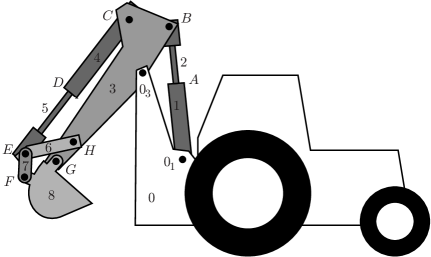
In order to get a uniform scheme, termed structural scheme, it is common to represent all the connections between the links by revolute joints as appears in Figure 2. Here joints and attach the excavator to the vehicle (fixed ground) and these special joints are marked with a small hatched triangle, and are called pinned joints. All other joints are called inner joints. A link which can be altered (e.g. by changing its length) is called a driving link. A driving link can be thought of as driving or changing the distance between its endpoints like the pistons in our excavator example, which may be modeled in the structural scheme by a rotation of an inserted link 1.
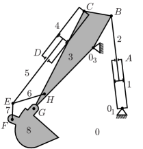
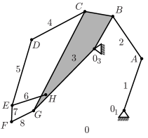
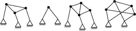
Once the engineering system is represented in the structural scheme, to start the analysis, all the driving links are deleted and replaced by pinned joints (mathematically speaking the driving links are contracted and their endpoints identified). In the current example, links 1 and 4 are deleted and joints A and D are pinned. Then, the system is decomposed into three Assur groups, each consisting of two links, one inner joint and two pinned joints. In the literature the Assur groups of this type are referred to as dyads [13]. The order of the decomposition is important. If an inner joint of a group, , becomes a pinned joint in group , then should precede .
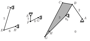
In our example (see Figure 3), the unique order of decomposition is: Dyad; Dyad; Dyad.
2.2 Degree of freedom of a mechanism: Grübler’s equation
The degree of freedom (DOF) of a linkage is the number of independent coordinates or measurements required to define its position.
In mechanical engineering [13], Grübler’s equation relates the (least number of internal) degrees of freedom of a linkage mechanism to the number of links and the number of joints in the mechanism. In the plane, if is the number of joints from which links emanate, then
| (1) |
In the example above because the fixed ground is considered a link, and , because the revolute joint is counted twice as it pins links 5, 6, and 7. By Grübler’s equation we get , which is correct as there are two driving links (two distances being controled). If these two driving links are removed and their ends pinned (identified) as in the example analysis, we have only 7 links left and the number of revolute joints is now 9, so . This is another indication that the drivers work independently.
Note that Grübler’s equation only gives a lower bound on the degree of freedom and there are many cases where the actual DOF is larger than the predicted one [13]. If a linkage contains a sub-collection of links pinned in such a way among themselves that the Grübler count is negative for the sub-collection, then the predicted DOF for the linkage might be smaller than the actual DOF (see Figure 4(a)). This situation can be detected and corrected by combinatorial means as we will describe in Laman’s Theorem, see §2.5 Theorem 1.
Counting techniques, however, cannot detect special geometries, e.g. parallelism or symmetry of links, which also might lead to a false Grübler DOF prediction. We will examine this type of geometric singularity of a combinatorially correct graph in [17].
2.3 Frameworks
For a linkage in which all the links are bars, with revolute joints at the two endpoints of the bar, we can rewrite Grübler’s equation in terms of graph theory, by introducing a graph whose vertices, , are the joints and whose edges, , are the bars. With denoting the set of vertices of valence , Grübler’s equation becomes
So if the edges of a graph embedded in the plane are interpreted as rigid bars and the vertices as revolute joints, the graph needs to have at least edges in order to have no internal degrees of freedom, an observation made already by Maxwell. The count will be central to the rest of the paper.
By a framework we mean a graph together with a configuration of into Euclidean space, for our purpose the Euclidean plane. We will always assume that the two ends of an edge (a bar) are distinct points). A motion of the framework is a displacement of the vertices which preserves the distance between adjacent vertices, and a framework is rigid if the only motions which it admits arise from congruences.
Let us assume that the location of a vertex is a continuous function of time, so that we can differentiate with respect to time. If we consider the initial velocities, , of the endpoints of a single edge under a continuous motion of a framework, then, to avoid compressing or extending the edge, it must be true that the components of those velocities in the direction parallel to the edge are equal, i.e.
| (2) |
A function assigning vectors to each vertex of the framework such that equation 2 is satisfied at each edge is called an first-order motion. If the only first-order motions are trivial, that is, they arise from first-order translations or first-order rotations of , then we say that the framework is first-order rigid in the plane. First-order rigidity implies rigidity, see for example [5].
In our excavator example not all links are bars. In the structural scheme link 8 is modeled by a bar because it contains only two pins, while link 3, which contains 5 pins appears as a “body”. We can replace such a body by a rigid subframework on these 5 vertices (or more). In general, any linkage consisting of rigid bodies held together by pin joints can be modeled as a framework by replacing the bodies with rigid frameworks.
2.4 The rigidity matrix
Any graph can be considered a subgraph of the complete graph on the vertex set , where is large enough. Let be a fixed configuration (embedding) of into .
Equation 2 defines a system of linear equations, indexed by the edges , in the variables for the unknown velocities . The matrix of this system is a real by matrix and is called the rigidity matrix. As an example, we write out coordinates of and of the rigidity matrix , in the case .
A framework is infinitesimally rigid (in dimension ) if and only if the submatrix of consisting of the rows corresponding to has rank . We say that the vertex set is in generic position if the determinant of any submatrix of is zero only if it is identically equal to zero in the variables . For a generically embedded vertex set, linear dependence of the rows of is determined by the graph induced by the edge set under consideration. The rigidity properties of a graph are the same for any generic embedding. A graph on vertices is generically rigid if the rank of its rigidity matrix is , where is the submatrix of containing all rows corresponding to the edges of , for a generic embedding of . The (generic) DOF of is defined to be .
2.5 Results for the plane
Linear dependence of the rows of the rigidity matrix defines a matroid on the set of rows and for generic configurations we speak about independent edge sets rather than independent rows of . For a generic embedding of vertices into we call the matroid on the complete graph obtained from the generic rigidity matroid in dimension on vertices, .
The following theorem characterizes .
Theorem 1.
(Laman [10]) The independent sets of are those sets of edges which satisfy Laman’s condition:
| (3) |
Laman’s Theorem was proved in 1970 and it was this theorem that promoted the use of matroids to attack rigidity questions. There are many equivalent axiom systems known for matroids. These can be used to reveal structural properties of various types and their relationships. The fact that matroids are exactly those structures for which independent sets can be constructed greedily has important algorithmic conseqences.
From the count condition in the inequalities (3) for independent edge sets it is straight forward to deduce count conditions for bases of (edge sets inducing minimally rigid or isostatic graphs), as well as for minimally dependent sets, or circuits, which will play a fundamental role in our analysis and will be treated in the next section.
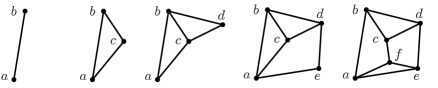
Independent sets of may be constructed inductively [20]. Given an independent edge set in , we can extend by new edges provided that the inequalities 3 are not violated. Starting with an independent set (e.g. a single edge):
-
(a)
We can attach a new vertex by two new edges and to the subgraph of induced by and is independent, see Figure 5a. This is also called -valent vertex addition.
-
(b)
Similarly, we can attach a new vertex by three new edges to the endpoints of an edge plus any other vertex in the subgraph of induced by , and is independent, see Figure 5b. This operation is called edge-split, because the new vertex is thought of as splitting the edge .
These Henneberg techniques developed in [20] have become standard in rigidity theory, see also [7], and when we resort to “the usual arguments” within some of the proofs to come, we have these standard proof techniques in mind. For further reference we state the following well known result.
Theorem 2 (Henneberg [20]).
Any independent set in can be obtained from a single edge by a sequence of -valent vertex additions and edge-splits.
2.6 Rigidity circuits
Minimally dependent sets, or circuits, in are edge sets satisfying and every proper non-empty subset of satisfies inequality (3). Note that these circuits, called rigidity circuits, always have an even number of edges. We will, as is commonly done, not distinguish between edge sets and the graphs they induce.
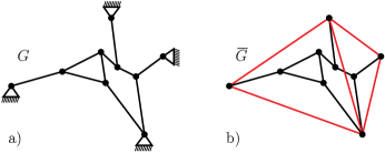
Similarly to the inductive constructions of independent sets (see Figure 5), all circuits in can be constructed from a tetrahedron (the complete graph on four vertices) by two simple operations, see [3], namely edge-split as in Figure 5b, and 2-sum, where the 2-sum of two (disjoint) graphs is obtained by “gluing” the graphs along an edge and removing the glued edge, see Figure 7.
Theorem 3 (Berg and Jordan [3]).
Any circuit in can be obtained from by a sequence edge-splits and 2-sums.
2.7 Isostatic Pinned Framework
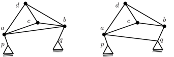
Given a framework associated with a linkage, we are interested in its internal motions, not the trivial ones, so following the mechanical engineers we pin the framework by prescribing, for example, the coordinates of the endpoints of an edge, or in general by fixing the position of the vertices of some rigid subgraph, see Figure 8. We call these vertices with fixed positions pinned, the others inner. (Inner vertices are sometimes called free or unpinned in the literature.) Edges among pinned vertices are irrelevant to the analysis of a pinned framework. We will denote a pinned graph by , where is the set of inner vertices, is the set of pinned vertices, and is the set of edges, where each edge has at least one endpoint in .
A pinned graph is said to satisfy the Pinned Framework Conditions if and for all subgraphs the following conditions hold:
-
1.
if ,
-
2.
if , and
-
3.
if .
We call a pinned graph pinned isostatic if and is rigid as an unpinned graph, where is a complete graph on a vertex set containing all pins (but no inner vertices). In other words, we “replace” the pinned vertex set by a complete graph containing the pins and call isostatic, if choosing any basis in that replacement produces an (unpinned) isostatic graph.
A pinned graph realized in the plane, with for the pins, and for all the vertices, is a pinned framework. A pinned framework is rigid if the matrix has rank , where is the rigidity matrix of with the columns corresponding to the vertex set of removed, independent if the rows of corresponding to are independent, and isostatic, if it is rigid and independent. The vertices of a pinned framework are in generic position if any submatrix of the rigidity matrix is zero only if it is identically equal to zero with the coordinates of the inner vertices as variables. The coordinates of the pins are prescribed constants.
Figure 8 shows an example of a pinned isostatic and a corresponding basis of .
It is common in engineering to choose pins in advance and their placement might not be generic, in fact not even in general position (no three points collinear), as it is sometimes necessary to have all pins on a line. The following result shows that this is not a problem.
Theorem 4.
Given a pinned graph , the following are equivalent:
(i) There exists an isostatic realization of .
(ii) The Pinned Framework Conditions are satisfied.
(iii) For all placements of with at least two distinct locations and all generic positions of the resulting pinned framework is isostatic.
Proof.
Let , and a maximal independent edge set of . Then by Theorem 1 we deduce that is isostatic if and only if the Pinned Framework Conditions are satisfied, so
In order to show we first show that we can extend to by a Henneberg sequence of 2-valent vertex additions and edge-splits (see Figure 5). To this end we de-construct first by removing inner vertices as follows. Assume that . Since and spans at most edges, we must have at least three edges joining the set of inner vertices to the pinned vertices . Therefore, if we sum over the valence of inner vertices, and denote the the set of edges with both endpoints in by , the ones with one endpoint in by , we obtain . So there will be some inner vertices of valence 2 or 3. If at this stage there is some vertex of degree , we can just remove it, to create a smaller graph with the same isostatic count. If there is some vertex of degree , then by the usual arguments [7, 20], it can be removed, and replaced by a new edge joining two of its neighbors, which were not yet joined in a remaining rigid subgraph (e.g. not both pinned), to create a smaller subgraph with the isostatic count. This produces a reverse sequence of smaller and smaller isostatic graphs until we have no inner vertices.
To obtain a realization, place in an arbitrary position with at least two distinct vertices. Create an isostatic graph whose vertex set contains , by, for example, ordering the vertices in with distinct positions arbitrarily, , adding edges between consecutive vertices and attaching an extra vertex, by edges . This graph is clearly isostatic, provided the point is not placed on the line through and for any , because it has the correct edge count and is rigid since it consists of a string of non-collinear triangles.
To complete the proof, we work back up the sequence of subgraphs we created in the de- construction process. We assume the current graph is realized as isostatic. When the next graph is created by adding a 2-valent vertex, then adding such a vertex in any position except on the line joining its two attachments gives a new isostatic realization.
When the next graph is created by an edge-split, note that at least one of the neighbors of the new vertex is inner, so this added inner vertex can be placed in a generic position ensuring that the three new attachments are not collinear. Therefore, by the usual arguments [7, 20], this insertion is also isostatic when placed along the line of the bar being removed, and therefore also when placed in any generic position. Since (iii) trivially implies (i), the proof is complete. ∎
A pinned graph satisfying the Pinned Framework Conditions must have at least two pins and in every isostatic realization of there must be at least two distinct pin locations. Placing all pins in the same location never yields an isostatic framework, but we can make an important observation about the DOF of such a “pin collapsed” framework.
Theorem 5.
Let be a pinned graph satisfying the Pinned Framework Conditions. Identifying the pinned vertices to one vertex yields a graph , and the DOF of is one less than the number of rigidity circuits contained in .
Proof.
Since , contains too many edges to be isostatic. If is rigid, it is overbraced by exactly one edge, hence contains exactly one rigidity circuit. If is not rigid, each of the rigidity circuits in must contain . If two rigidity circuits intersected in a vertex other than , the union of their edge sets, together with the pinned subgraph would violate the Pinned Subgraph Conditions. Therefore all circuits in have exactly the vertex in common. Removing exactly one edge from each circuit yields a basis for in , establishing the desired connection between the DOF and the number of circuits. ∎
3 Characterizations of Assur graphs
We start with two citations from the mechanical engineering literature as motivation for our combinatorial conditions. The following definition appears in [23]: “An Assur group is obtained from a kinematic chain of zero mobility by suppressing one or more links, at the condition that there is no simpler group inside”. In [18] we find: “An element of an Assur group is a kinematic chain with free or unpaired joints on the links which when connected to a stationary link will have zero DOF. A basic rigid chain is a chain of zero DOF and whose subchains all have DOF greater than zero. In other words an element of an Assur group is a basic rigid chain with one of its links deleted”.
These descriptions from the engineering literature are not definitions in the mathematical sense, but rather use ‘minimality’ informally, as in the original work of Assur. We are now ready to give a formal definition by confirming a series of equivalent combinatorial characterizations of Assur graphs. These statements are new, and (iii) and (iv) come from the conjectures offered by Offer Shai at the workshop.
3.1 Basic Characterization of Assur graphs
Theorem 6.
Assume is a pinned isostatic graph. Then the following are equivalent:
(i) is minimal as a pinned isostatic graph: that is for all proper subsets of vertices , induces a pinned subgraph with .
(ii) If the set is contracted to a single vertex , inducing the unpinned graph with edge set , then is a rigidity circuit.
(iii) Either the graph has a single inner vertex of degree or each time we delete a vertex, the resulting pinned graph has a motion of all inner vertices (in generic position).
(iv) Deletion of any edge from results in a pinned graph that has a motion of all inner vertices (in generic position).
Proof.
(i) implies (iv) If we delete an edge, there must be a motion by the count. If there is a set of inner vertices that are not moving, in generic position, then these vertices, and their edges to the pinned vertices, must form a proper isostatic pinned subgraph contradicting condition (i).
(iv) implies (iii) Removing an edge with an endpoint of valence produces a graph with a pendant edge. This must be the only inner vertex, since any other inner vertices are not moving, contradicting (iv). Since removing a single edge results in a motion of all inner vertices, removing all edges incident with one particular vertex results in a framework with a motion on all the remaining vertices.
Conversely, (iii) implies (i) If the graph contains a minimal proper pinned subgraph, then removing any vertex outside of this subgraph will produce a motion at most in the vertices outside of the subgraph. This contradicts (iii).
(i) is equivalent to (ii) If is a pinned isostatic graph, then identifying the vertices in to a single vertex yields a graph with , so is dependent and if the minimality condition in (i) is satisfied, it must be a rigidity circuit. Conversely, if is a rigidity circuit, we can pick an arbitrary vertex of and call it . Splitting into a vertex set , , (where may have as many vertices as the valence of in allows) and specifying for each edge with endpoint a new endpoint from so that no isolated vertices are left, yields an isostatic pinned framework satisfying the minimality condition. ∎
This theorem provides a rigorous mathematical definition: an Assur graph is a pinned graph satisfying one of the four equivalent conditions in Theorem 6.
Condition (i) is a refinement of the Grübler count (1), in a form which is now necessary and sufficient.
Condition (ii) translates the minimality condition to minimal dependence in and thus serves as a purely combinatorial description of Assur graphs and may be checked by fast algorithms [8, 11].
Conditions (iii) and (iv) are similar in nature. Condition (iii) provides the engineer with a quicker check for the Assur property for smaller graphs than (iv), since there are fewer vertices than edges to delete. However, condition (iv) tells the engineer that a driver inserted for an arbitrary edge will (generically) move all inner vertices. We will expand on this property in [17]
3.2 Decomposition of general isostatic frameworks
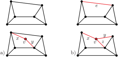
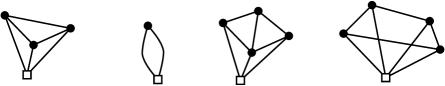
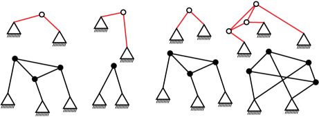
We now show that a general isostatic framework can be decomposed into a partially ordered set of Assur graphs. The given framework can be re-assembled from these pieces by a basic linkage composition. Figure 11 shows isostatic pinned frameworks and Figure 13 indicates their decomposition.
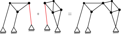
Given two linkages as pinned frameworks and and an injective map , the linkage composition is the linkage obtained from and by identifying the pins of with their images .
Lemma 1.
Given two pinned isostatic graphs , , the composition creates the new composite pinned graph: which is also isostatic.
Proof.
By the counts, we have , and , so . A similar analysis of the subgraphs confirms the isostatic status. ∎
Under this operation, the Assur graphs will be the minimal, indecomposable graphs. We can show that every pinned isostatic graph is a unique composition of Assur graphs, which we will call the Assur components of .
Theorem 7.
A pinned graph is isostatic if and only if it decomposes into Assur components. The decomposition into Assur components is unique.
Proof.
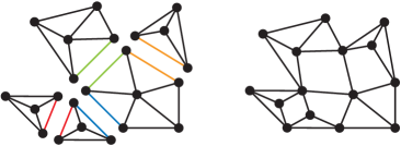
Take the isostatic pinned framework, and identify the ground pins. This is now a dependent graph. Using properties of , see [4], we can identify minimal dependent subgraphs - which, by Theorems 5 and 6, are Assur components after the pins are separated. These are the initial components. When all of these initial components are contracted in step two, we seek additional Assur components. We iterate the process until only the ground is left. ∎
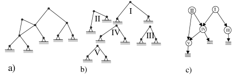
The decomposition process described in the proof of Theorem 7 naturally induces a partial order on the Assur components of an isostatic graph: component if occurs at a higher level, and has at least one vertex of as a pinned vertex. The algorithm for decomposing the graph guarantees that means that occurs at a later stage than . This partial order can be represented in an Assur scheme as in Figure 14. This partial order, with the identifications needed for linkage composition, can be used to re-assemble the graph from its Assur components.
Replacing any edge in an isostatic framework produces a 1 DOF linkage. The decomposition described in Theorem 7 permits the analysis of this linkage in layers. In fact, we can place drivers in each Assur component to obtain linkages with several degrees of freedom and their complex behavior can be simply described by analyzing the individual Assur components. This process of adding drivers is studied in more detail in [17].
3.3 Generating Assur graphs
We summarize inductive techniques to generate all Assur graphs. Engineers find such techniques of interest to generate basic building blocks for synthesizing new linkages.
The dyad is the only Assur graph on three vertices. There is no Assur graph on four vertices. An Assur graph, whose corresponding rigidity circuit is is called a basic Assur graph.
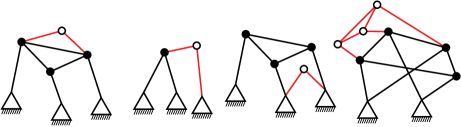
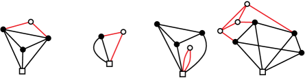
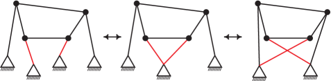
To generate all Assur graphs (on five or more vertices) we use Theorem 6(ii) together with Theorem 3 to generate all rigidity circuits. To get from a rigidity circuit to an Assur graph, we choose a vertex of and split it into two or more pins (as in the proof of Theorem 6). The choice of , the splitting of into a set of pins (), and choosing for each edge incident to an endpoint from allows us to construct several Assur graphs from one rigidity circuit, see Figure 17. We say that and are related by pin rearrangement if (see Figure 17).
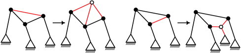
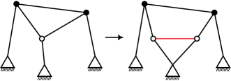
The operations of edge-split and 2-sum, which were used to generate rigidity circuits inductively, can also be used directly on Assur graphs to generate new Assur graphs from old, see Figures 15 and 16. In particular, the operation of 2-sum may be of practical value if, for space reasons for example, a pinned vertex is to be eliminated, see Figure 16.
Theorem 8.
All Assur graphs on 5 or more vertices can be obtained from basic Assur graphs by a sequence of edge-splits, pin-rearrangements and -sums of smaller Assur graphs.
Since mechanical engineers might want to have additional tools readily available for generating Assur graphs, one can seek additional operations under which the class of Assur graphs is closed. Vertex-split (creating two vertices of degree at least three) is another operation which takes a rigidity circuit to a rigidity circuit, and therefore takes an Assur graph with at least three vertices to a larger Assur graph (Figure 18). This is, in a specific sense, the dual operation to edge-split [4]. More generally, [4] explores a number of additional operations for generating larger circuits from smaller circuits. Each of these processes will take an Assur graph to a larger Assur graph.
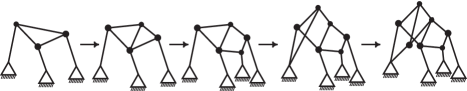
The inductive constructions for Assur graphs can be used to provide a visual certificate sequence for an Assur graph. If we are given a sequence of edge-splits and 2-sums starting from a dyad and ending with , see Figure 19, it is trivial to verify that is an Assur graph. We constructed such a sequence in the proof of Theorem 4. It is well known, see [20], that there are exponential algorithms to produce such a certificate. However, there are other fast algorithms, for example the so called pebble games, see [8, 11] to detect all the rigidity properties of graphs that can be adapted to verify the Assur property.
4 Concluding comments
The paper introduces, for the first time, the concept of Assur graphs, in the rigorous mathematical terminology of rigidity theory. This work paves a new channel for cooperation between the communities in kinematics and in rigidity theory. An example for such channel is the material appearing in §2.7 showing how to transform determinate trusses used by the kinematicians into isostatic frameworks, widely employed by the rigidity theory and structural engineering communities.
At this point, it is hard to predict all the practical applications that are to benefit from this new relation between the disciplines. Nevertheless, we anticipate practical results from the use of rigidity theory in mechanisms as introduced in the paper. Examples of such results, include using rigid circuits from rigidity theory to find the proper decomposition sequence of pinned isostatic framework into Assur components (Section 3.2) and generation of Assur graphs by applying two known operations to their corresponding rigidity circuits (Section 3.3).
It is expected that new opportunities will be opened up, for example, for mechanical engineers to comprehend topics in rigidity theory that are used today in many disciplines, including biology, communications and more. Mechanical engineers in the west may be motivated to use the Assur graphs (Assur groups) concept as it is widely applied in eastern Europe and Russia.
Decomposing a larger linkage into Assur graphs and analyzing these pieces one at a time is an effective way to analyze the overall motion, working in layers. This paper has given a precise mathematical foundation for the Assur method as well as a proof of its correctness and completeness.
We have followed standard engineering practice and developed the theory in the language of bar-and-joint frameworks, but of course there is no need to replace a larger link (rigid body) with an isostatic bar-and-joint sub-framework to apply the counting techniques. It is simply convenient to do so in order to streamline notation and graphics. All of our results may be reworded in terms of body and bar structures or body and pin frameworks. This presentation would be much closer to the original example in Figures 1 and 2 and the counts of §2.2.
To extend this type of analysis to 3D linkages, the lack of good characterization of isostatic bar-and-joint frameworks in D is an initial obstacle. However, if we focus on body-and-bar or body-and-hinge structures (the analog of body-and-bar and body-and-pin frameworks in the plane) then the generic DOF of these structures is computable by analogous counting techniques [21, 22], and all our combinatorial methods will carry over sucessfully.
References
- [1] I. I. Artobolevskiĭ. Teoriya mehanizmov i mašin. Gosudarstv. Izdat. Tehn.-Teor., Moscow-Leningrad, 1951. 2d ed.
- [2] L. V. Assur. Issledovanie ploskih steržnevyh mehanizmov s nizšimi parami s točki zreniya ih struktury i klassifikacii. Izdat. Akad. Nauk SSSR, 1952. Edited by I. I. Artobolevskiĭ.
- [3] Alex R. Berg and Tibor Jordán. A proof of Connelly’s conjecture on 3-connected circuits of the rigidity matroid. J. Combin. Theory Ser. B, 88(1):77–97, 2003.
- [4] Laura Chavez, Lily Moshe, and Walter Whiteley. Extending basis and circuits for 2-rigidity via tree coverings. preprint, 2005.
- [5] Robert Connelly. The rigidity of certain cabled frameworks and the second-order rigidity of arbitrarily triangulated convex surfaces. Adv. in Math., 37(3):272–299, 1980.
- [6] Henry Crapo and Walter Whiteley. Spaces of stresses, projections, and parallel drawings for spherical polyhedra. Beitraege zur Algebra und Geometrie / Contributions to Algebra and Geometry, (35): 259–281, 1994.
- [7] Jack Graver, Brigitte Servatius, and Herman Servatius. Combinatorial rigidity, volume 2 of Graduate Studies in Mathematics. American Mathematical Society, Providence, RI, 1993.
- [8] Donald Jacobs, and Bruce Hendrickson An algorithm for two-dimensional rigidity percolation: the pebble game, J. Comput. Phys. (137): 346–365, 1997,
- [9] Bruce Hendrickson. Conditions for unique graph realizations. SIAM J. Comput., 21(1):65–84, 1992.
- [10] G. Laman. On graphs and rigidity of plane skeletal structures. J. Engrg. Math., 4:331–340, 1970.
- [11] Audrey Lee and Ileana Streinu. Pebble Game Algorihms and -sparse graphs, 2005 European Conference on Combinatorics, Graph Theory and Applications (EuroComb ’05), DMTCS Proceedings: 181–186, 2005
- [12] S. Mitsi, K.-D. Bouzakis, G. Mansour, and I. Popescu. Position analysis in polynomial form of planar mechanisms with Assur groups of class 3 including revolute and prismatic joints. Mech. Mach. Theory, 38(12):1325–1344, 2003.
- [13] Robert L. Norton. Design of Machinery: An Introduction To The Synthesis and Analysis of Mechanisms and Machines. McGraw Hill, New York, 2004.
- [14] R. Penne. Relative Centers of Motion, Implicit Bars and Dead-Center Positions for Planar Mechanisms. Preprint Department of Industrial Sciences and Technology, Karel de Grote-Hogeschool, Antwerp, Belgium, Rudi.Penne@kdg.be, 2007.
- [15] G. R. Pennock and G. M. Kamthe. A study of dead-center positions of single-degree-of-freedom planar linkages using assur kinematic chains,. IMechE J. Mech. Eng. Sci., Special Issue on Kinematics, Kinematic Geometry, and their Applications, An Invited Paper, in press., 2006.
- [16] O. Shai. Deriving structural theorems and methods using Tellegen’s theorem and combinatorial representations. Internat. J. Solids Structures, 38(44-45):8037–8052, 2001.
- [17] Brigitte Servatius, Offer Shai, and Walter Whiteley. The combinatorial characterization of Assur graphs. Preprint, 2008.
- [18] Rajesh P. Sunkari and Linda C. Schmidt. Structural synthesis of planar kinematic chains by adapting a mckay-type algorithm. Mechanism and Machine Theory, 41(9):1021–1030, 2006.
- [19] Tiong-Seng Tay. A new proof of Laman’s theorem. Graphs Combin., 9(4):365–370, 1993.
- [20] Tiong-Seng Tay and Walter Whiteley. Generating isostatic frameworks. Structural Topology, (11):21–69, 1985.
- [21] Neil White and Walter Whiteley. The algebraic geometry of motions of bar-and-body frameworks. SIAM J. Algebraic Discrete Methods, 8(1):1–32, 1987.
- [22] Walter Whiteley. Rigidity and Scene Analysis. in Handbook of Discrete and Computational Geometry, 2nd Edition J. O’Rourke and J. Goodman (eds): 1327-1354, 2004.
- [23] Bernard Yannou and Adrian Vasiliu. Design platform for planar mechanisms based on a qualitative kinematics.