Possible resolution of the Casimir force finite temperature correction “controversies”
Abstract
By considering the effect of diffusion on the external electric field response of charge carriers in metals and semiconductors, it is shown that the finite temperature correction proposed Boström and Sernelius requires substantial modification, and there is no large correction as suggested for good conductors. The apparent violation of the Third Law of Thermodynamics of the various proposed temperature corrections to the Casimir force is also resolved. Finally, the effect of Debye screening on electrostatic calibrations between pure germanium surfaces is calculated.
I Introduction
In our recent experimental work aimed at a precision measurement of the Casimir force between pure germanium (Ge) plates 1 , we have discovered that the electrostatic calibration for Ge, a semiconductor, is substantially different from what was expected, assuming Ge to be a good conductor. The problem is that a static electric field can propagate a finite distance into a semiconductor; this distance is determined by the combined consideration of diffusion and field driven electric currents, leading to an effective field penetration length (Debye-Hückel length)
| (1) |
where is the total carrier concentration, which for an intrinsic semiconductor, . For intrinsic Ge m,while for a good conductor, it is less than 1 nm. is independent of the applied field so long as the applied field times is less than the thermal energy, where is Boltzmann’s constant. In this limit, and at sufficiently low frequencies and wavenumbers, thermal diffusion dominates the field penetration into the material. A sufficiently low frequency for Ge would be GHz, where is a typical thermal velocity of a carrier.
An analysis of the electrostatic energy between parallel plates is given in the Appendix below, as well as the effect of field amplitude on . This analysis is crucial toward our ongoing experimental efforts, especially for the electrostatic calibration.
In light of this analysis, it has become clear that none of the recent papers describing finite temperature effects on the Casimir force have taken into account the thermal diffusion of carriers (electrons and/or holes) in the treatment of the boundary value problem. As such, a comprehensive review of recent work will not be presented here; only the work by Boström and Sernelius, that led to the recent “controversy,” will be discussed2 .
II Calculation of the Thermal Correction
To calculate the effects of finite temperature,the electromagnetic mode photon excitation number of due to zero point fluctuations is replaced by
| (2) |
which has simple poles at
| (3) |
where in the following discussion we take only integers .
Following 2 , the integral over in determining the field energy between two flat plates is replaced by the sum over the poles that occur at the Matsubara frequencies, ,
| (4) |
where the prime indicates a factor of for the term, and for the modes (electric field parallel to the surface)
| (5) |
where represents the electromagnetic field wavenumber in the space between the plates, in direction perpendicular to the plates.
The function in the integral, for the mode, is
| (6) |
| (7) |
where represents the space between the plates (0) or inside the plates, (1), and is the respective electric permittivity along the imaginary frequency axis, and is the plate separation.
It is argued in 2 that for realistic materials, and hence does not contribute to the energy that leads to the Casimir force between the plates. For example, the low-frequency permittivity of a metal is given by the conductivity ,
| (8) |
for which at .For distances greater than a few m, for K, the net force is reduced by a factor of two compared to what is expected for a near perfect conductor if both the and modes are included.
This result is in contradiction to experimental results, particularly 3 . There has been much discussion of this correction, but to now, the effect of diffusive field screening has not be taken into account in a satisfactory manner, or at all.
III Inclusion of the Debye Screening Length
For realistic conducting materials (metal, semiconductor), Eq. (7) is not possibly correct, for we know an electric field near the surface causes charges to move, and this tends to screen out the applied field. Electric fields applied either parallel or perpendicular to the surface will be screened, varying compared to the field at the surface, in the material, as
| (9) |
which is valid when (or for fields perpendicular to the surface).
The fact that electric fields do not penetrate any appreciable distance into even very poor conductors is experimentally well-known. Eq. (7) incorrectly describes the observed penetration of low frequency fields into conductors.
The screening effect can be treated in a heuristic fashion. The exact solution to the combined electrodynamic and diffusion problem is beyond the scope of the present note, the intent of which is to illustrate an effect that has been overlooked. Noting that is independent of frequency at low frequencies ( Hz), and that and its derivative are continuous across the boundary, we can rewrite Eq. 7) to include the spatial variation due to Debye screening,
| (10) |
assures continuity of the derivative across the boundary. The point is that the wavenumber in the material cannot be less than .
For this modified function, for , is equivalent to the perfect conductor result. Thus the large correction suggested in 2 applies only to materials where charges are not free to move, and diffusive effects do not enter. We can question whether this condition can ever really be met, but for any realistic slightly conducting material at finite temperature, there will always be a finite screening length, and hence a full contribution from the , mode, for good conductors where is large to frequencies of order Hz. A detailed calculation for Ge is required because starts falling off for frequencies above 10 GHz, in the region where the thermally excited photons contribute most significantly 4 .
IV Violation of the Third Law?
It has been suggested that the term in Eq. () show a manifest violation of the Third Law of Thermodynamics (sometimes referred to as the Nernst Heat Theorem) because the system entropy (identifying as the free energy ), given by
| (11) |
is not zero in the limit .This conundrum has been addressed and clarified in 5 , but there is a simpler argument that will be presented here.
In particular, we can question what it means to convert the integral over into a contour integral and hence sum over the Matsurba frequencies. If we did not convert this integral into a sum, the separate identification of the zero frequency contribution would not be made. Specifically, does not appear in the Casimir force calculation expect through the mode photon number. Differentiating Eq. (2) with , we find
| (12) |
which indeed goes to zero at .
Alternatively, if we consider the entire sum, Eq. (4), let go to zero, we find,
| (13) |
where the simple substitution was made. Hence, the temperature does not appear explicitly in the total free energy, and the entropy indeed goes to zero at zero temperature.
The apparent violation of the Third Law is due simply to the isolation of a single term in the total free energy. Not considering the entire system in calculating the entropy is generally considered a sophomoric error.
V Conclusion
By including the effect of charge movement and screening through the Debye length, it is shown that the large correction to the Casimir force predicted in 2 is not applicable to realistic materials. It should be noted that these correction apply to all conductors when the distance scale approaches the Debye length, which for a good conductor is 0.1 nm. The Debye length is constant in good conductors up to frequencies of order Hz, so we can expect the full perfectly conducting force for any metal, at large separations.
The case of a semiconductor like Ge is slightly more complicated because begins to increase for frequencies of order 10 GHz, so a detailed anlysis of this case is required. However, it can be expected that there is a significant contribution from the mode.
It is also shown that the apparent violation of the 3rd Law of Thermodynamics is due to the isolation of a single term in an expansion that becomes an integral in the limit of .
VI Appendix
The potential in a plane semiconductor, if the potential is defined on a surface is
| (14) |
where is the Debye-Hückle screening length, defined previously.
We are interested in finding the energy between two thick Ge plates separated by a distance , with a voltages and applied to the backs of the plates. In this case, the field is normal to the surface. After we find the energy per unit area, we can use the Proximity Force Theorem to get the attractive force between a spherical and flat plate.
Let refer to the surface of the plate 1, and refer to the surface of plate 2. By symmetry, the potential at the center position between the plates is zero. The potential in plate 1 can be written
| (15) |
and the space between the plates
where we assume the field is uniform. , the surface potential, is to be determined.
We need only consider the boundary conditions in plate 1, which are
(which has already been used)
where the last two imply that is continuous across the boundary.
The solution is
| (16) |
With this result, it is straightforward to calculate the total field energy per unit area in both plates and in the space between the plates. The result is
| (17) |
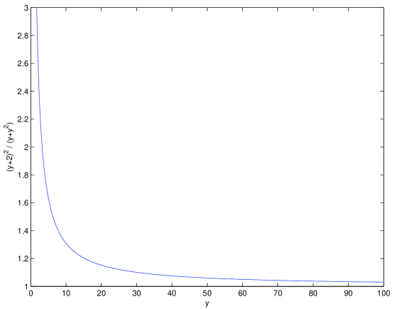
where the dimensionless length has been introduced.
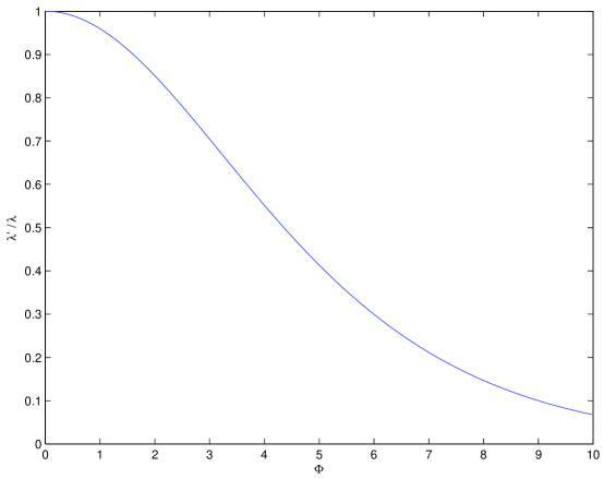
If is large compared to , the effective penetration depth increases because the charge density is modified in the vicinity of the surface. The potential in the plates is no longer a simple exponential, however one can define an effective shielding length 6
| (18) |
where
| (19) |
with the results plotted in Fig. 2. Given that meV, at plate separations of order 1 m for Ge this begins to be a large correction when voltages larger than 60 mV are applied between the plates at separations of order m.
References
- (1) S.K. Lamoreaux and W.T. Buttler, Phys. Rev. E 71, 036109 (2005).
- (2) M. Boström and B. Sernlius, Phys. Rev. Lett. 84, 4757 (2000).
- (3) A. Lambrecht, S. Reynaud, and S.K. Lamoreaux, Phys. Rev. Lett. 84, 5672 (2000), and references therein.
- (4) J.R. Torgerson and S.K. Lamoreaux, Phys. Rev. E 70, 47102 (2004).
- (5) M. Boström and B.E. Sernelius, Physica A 339, 53 (2004).
- (6) A.I. Spitsyn and V.M. Vanstan, Radiophysics and Quantum Electronics 36, 752 (1994).