Spin-orbital coupling effect on Josephson current through a superconductor heterojunction
Abstract
We study spin-orbital coupling effect on the Josephson current through a superconductor (SC) heterojunction, consisting of two s-wave superconductors and a two-dimensional electron gas (2DEG) layer between them. The Rashba-type (RSOC) and/or Dresselhaus-type (DSOC) of spin-orbital coupling are considered in the 2DEG region. By using the lattice Bogoliubov-de Gennes equation and the Keldysh formalism, we calculate the DC supercurrent flowing through the junction and find that the critical current exhibits a damped oscillation with both the strength of SOC and the layer length of 2DEG; especially, the strength ratio between RSOC and DSOC can also induce switching between the state and the state of the SC/2DEG/SC junction as well. This - transition results from the fact that SOC in a two-dimension system can lead to a pseudo-magnetic effect on the flowing electrons like the effect of a ferromagnet, since the time reversal symmetry of the system has already been broken by two SC leads with different macroscopic phases.
pacs:
Pacs numbers: 74.50.+r, 74.45.+cThe issue of Josephson current sign reversal in a superconductor/ferromaget/superconductor (SC/FM/SC) heterojunction has recently drawn a great deal of attention1 ; 2 ; 3 due to its experimental observation and potential applications to spintronics and quantum computing.4 ; 5 ; 6 ; 7 ; 8 The physical origin of the Josephson effect is the breakdown of time reversal symmetry (TRS) in SC/SC junctions due to the SC macroscopic phase difference. Between the two SC leads in the junction is either an insulator or a ”weak link” such as normal metal (NM), semiconductor, and so on. The DC Josephson effect can be understood by the Andreev reflection processes of quasiparticles9 with energy smaller than the superconducting energy gap, an electron impinging on one of the interfaces is Andreev reflected and converted into a hole moving in the opposite direction, thus generating a Cooper pair in an SC; this hole is consequently Andreev reflected at the second interface and is converted back to an electron, leading to the destruction of a Cooper pair in the other SC. As a result of this cycle, a pair of correlated electrons are transferred from one SC to another, creating a supercurrent flow across the junction.1
When an FM is inserted between the two SC leads, the current-carrying Andreev bound states are spin-splitted and shifted in an oscillatory way. FM favors to align the electron spin due to the FM exchange interaction, whereas the ordinary spin singlet Cooper pair consists of two spin-antiparallel electrons; thus FM tends to destroy the superconductivity and the Josephson current in SC/FM/SC junctions would be depressed compared with SC/NM/SC junctions. Furthermore, the Cooper pair is associated with a nonzero momentum due to spin splitting from the FM exchange interaction and the Josephson current exhibits a damped oscillating behavior with the FM layer length or the FM exchange strength, i.e., the - transition.10 ; 11 ; 12 ; 13 ; 14 ; 15 ; 16 ; 17 ; 18 ; 19 ; 20 ; 21 ; 22 ; 23 The -state of the SC/FM/SC junction is the Josephson current flowing in the direction opposite to the phase difference between the two SCs. To realize systematically the - state switching in a single SC/FM/SC junction, it needs to change either the length of the FM layer or the FM exchange strength; however, as a matter of fact, it is very difficult to do this in an experiment. Since the tunability of a system is of importance for experimental observation, some alternatives have been proposed; for example, the SC/FM/FM/SC junction with noncollinear magnetizations has been investigated by Pajović et al.24 and the - transition can be found by modulating the relative direction of the FM moments. Dolcini and Giazotto25 proposed to use Aharonov-Bohm interferometry to realize a fully controllable Josephson junction.
The Josephson current flowing through a two-dimensional electron gas (2DEG) region with Rashba (RSOC) and/or Dresselhaus (DSOC) spin orbital coupling has also been studied, because the pseudomagnetic field from SOC may lead to the same effect on the Josephson current as FM.26 ; 27 ; 28 ; 29 Several studies26 ; 27 have shown that in the one-dimension case the SOC can hardly exert any effect unless the Zeeman splitting from an external magnetic field is included. It was generally argued that SOC does not break the TRS of the system and cannot function like an FM. However, Dell’Anna et al.29 argued that TRS has already been broken by the supercurrent and found that SOC can have a huge effect on the Josephson current in a quantum dot system, although they did not find the - transition behavior since only two electron levels are considered in the quantum dot.
In this work, we restudy the SOC effect on the DC Josephson current through a SC/2DEG/SC junction in the clean limit and with the multilevels in the 2DEG being taken into account. When TRS of the system is broken by the two SCs with different macroscopic phases, the pseudomagnetic field from SOC should cause an effect (hereafter referred to as pseudo-magnetic effect) on the electron transport property, resembling the exchange field effect in a FM; however, for 1D transport, the pseudo-magnetic effect from SOC should disappear.30 Based on this analysis, we calculate the Josephson current flowing in a SC/2DEG/SC junction by using the discrete BdG equation and Keldysh Green’s functions. It is shown that the Josephson current exhibits a damped oscillation as a function of the strength of SOC, the length of the 2DEG layer, and the strength ratio between RSOC/DSOC. This - transition is the same as that found in SC/FM/SC junctions. However, the - transition induced by SOC is much easier to be realized in experiment since the strength of SOC can be modulated to a large extent by an external electric field perpendicular to the plane of 2DEG.31
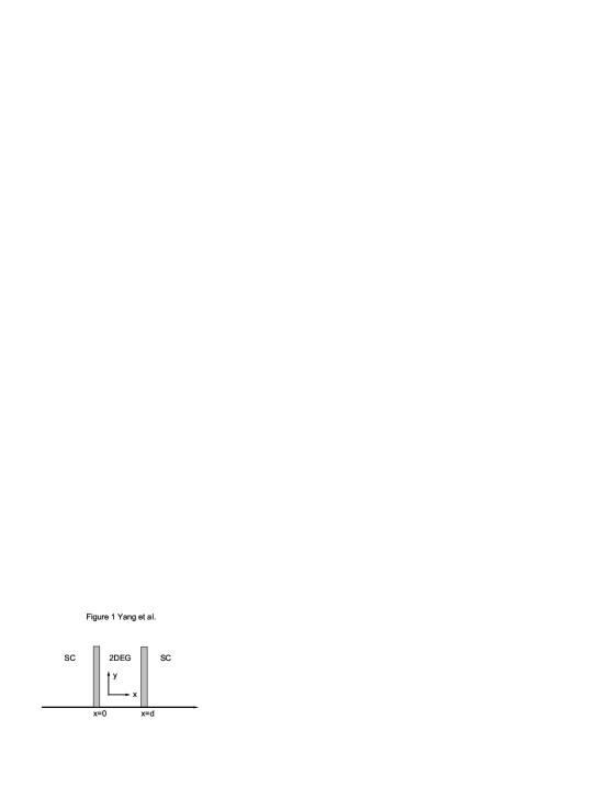
We consider a clean SC/2DEG/SC heterojunction, consisting of two semi-infinite SC leads and a 2DEG layer with a length between them, as shown in Fig. 1. The interfaces between 2DEG and SCs are set at and and the current flows along the -direction. In the 2DEG layer both RSOC and DSOC are considered, which come from the structure asymmetry of the material32 ; 33 and are expressed as
| (1) |
where and are the coupling constants of RSOC and DSOC, repectively, and RSOC can be directly modulated by an external electric field perpendicular to the 2DEG plane,31 and are the two components of the momentum operator p, and are the Pauli matrices. The difference between these two SOCs is the different directions of the pseudomagnetic fields from SOC for the same electron momentum. By introducing a ratio angle , the equation above can be rewritten as
| (2) |
Here , , and , , and . The angle denotes not only the strength ratio between RSOC and DSOC, but also the pseudomagnetic field direction for the mixture of RSOC and DSOC, which is similar to the rotation angle of the spin axis,30 as can be seen in the renormalized and .
The two SC leads are described in the framework of standard BCS formalism with a macroscopic phase difference . In the absence of external applied field, the mean-field Hamiltonian of the SC/2DEG/SC junction reads34
| (3) |
| (4) |
| (5) |
| (6) |
Here and are respectively the discretized BdG equation of the left and right SC leads; is the Hamiltonian of the 2DEG region, i.e., a free electron model with SOC included; is the tunneling Hamiltonian between the 2DEG and the left and right SC leads. is the creation (annihilation) operator of an electron at site () with spin , is the site-energy, is the hopping energy with the lattice constant , and denotes the SOC strength in the lattice representation. is the pair potential in the left (right) SC lead with a macroscopic phase , is the chemical potential which is constant everywhere in our model due to zero applied bias in the junction. is the hopping strength between the left (right) lead and 2DEG, which is independent of spin so that no spin flip effect occurs when quasiparticles tunnel through the interfaces; it can also represent the strength of the interface barrier between the SC lead and the 2DEG region.
Although we consider a clean system without impurity, the Hamiltonian above is not limited to this system and can describe systems with other band structures as well as different pair potential symmetry. Along the direction of the junction in Fig. 1, the translational symmetry is preserved so that the electron momentum is a good quantum number and summation in Eq. 3 over sites can be transformed to the -space, e.g.,
| (7) |
Other components of the Hamiltonian (Eq. 3) can be treated in the same way, thus the numerical calculation will be reduced greatly compared with a finite size (along the -direction) system. We focus on the supercurrent through the interface between the SC and 2DEG, thus, the current density operator is given by where is the electron operator in the left SC, and after commutation the steady current density reads35
| (8) |
is the lesser Green’s function defined in Nambuspin space, with denoting the quantum statistical average. is the transverse width of the junction, the subscripts stands for the summation over the spin-up and spin-down components of the electron current, i.e., the (1,1) and (3,3) matrix elements. Since we consider the DC Josephson effect and no bias is applied on the system, the lesser Green’s function could be obtained by the equilibrium equation with being the Fermi-Dirac distribution function, is the retarded (advanced) Green’s function, which fulfills the Dyson equation, e.g.,
| (9) |
where is the surface Green’s function of the left SC lead and is the coupled Green’s function of the 2DEG, is the left tunneling matrix of Eq. (3d) in the Nambuspin space. The retarded Green’s function can be calculated by direct matrix inversion or the recursive method,36 where is the 2DEG Hamiltonian Eq. (3b) in the Nambuspin space and is the self-energy from the left (right) SC lead.
In the numerical calculation, the hopping energy is set as the energy unit , the chemical potential takes and the pair potentials in the two SC leads are assumed to be equal, . The Josephson current is calculated at zero temperature based on Eq. 5 and the current phase relations are shown for different strength ratio angles in Fig. 2. The hopping term stands for the interface transparency between the SC leads and 2DEG; is set in the calculation to denote full transparency of the interfaces so that deviates from the sinusoidal relation as shown in Fig. (2a). The case (dashed-line) exhibits the coexistence of the and states, which suggests a - transition of the junction should occur upon changing the angle and other parameters. In Fig. (2b), it is expected that can approximate a harmonic function for low interface transparency .
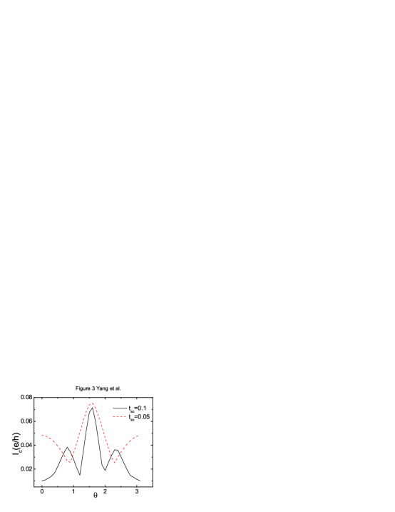
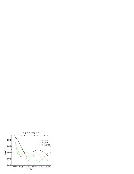
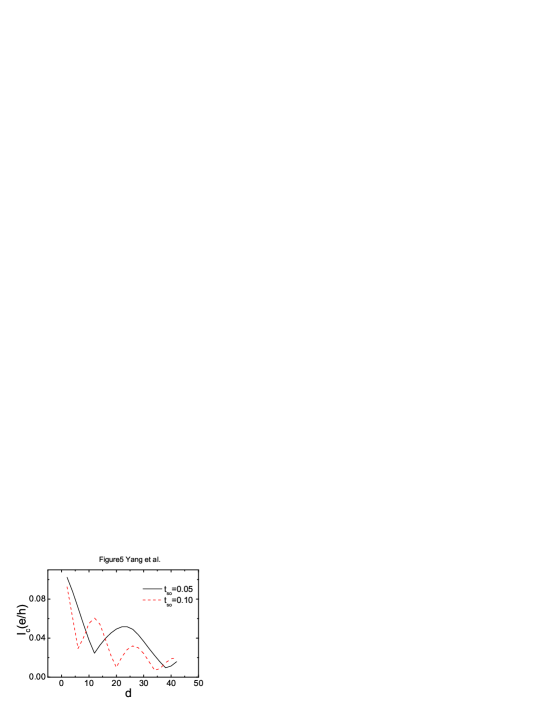
In Fig 3, the critical Josephson current is presented as a function of the angle for different SOC strength and 2DEG layer length . The dips in these curves correspond to the - transitions and the oscillation period decreases with the SOI strength. Changing is equivalent to modulating the relative pseudomagnetic field direction, which is perpendicular to the electron-momentum direction for RSOC while for DSOC, the pseudomagnetization direction is complementary to RSOC by exchanging the spin axis.30 Here the mixture of RSOC and DSOC is similar to the SC/FM/FM/SC junction with noncollinear FM moments studied by Pajović et al.,24 who found can oscillate with the angle between the two magnetizations. In Fig. 4 and Fig. 5, the critical current is also shown to exhibit the - transition by varying either the SOC strength (Fig. 4) or the 2DEG layer length (Fig. 5). The damped oscillation of suggests that the -state of the junction stems from the psuedo-magnetic effect of SOC, which is similar to an SC/FM/SC junction in terms of physical origin.
The state of the SC/FM/SC junction results from the Cooper pair (coherent electron and hole in FM) being associated with a nonzero momentum due to the FM exchange interaction, which can lead to an oscillating with the FM exchange strength as well as the FM layer length. For the studied SC/2DEG/SC junction, SOC maintains the TRS of the system itself on the whole because each electron sees a pseudomagnetic field from Eq. 2; the system does not have any pseudo-magnetic effect, which resembles breaking the TRS, when a summation is taken over all electrons. However, in the present case the TRS of system has already been broken by the current, and the SOC should have effects on the transport properties. By summing over those electrons (momenta) contributing to the current, the pseudo-magnetic effect of SOC appears; for example, the anomalous tunneling magnetoresistance (ATMR) observed in experiments37 is generally attributed to the SOC effect which is a pseudo-magnetic effect on the TMR. When a Josephson current is flowing through the SC/2DEG/SC junction, SOC can affect it definitely and can exhibit a damped oscillation like in an SC/FM/SC junction.
For one-dimensional SC/2DEG/SC junctions with SOC or only perpendicular injection considered (), one cannot obtain - transition as those shown in Fig. (3-5). The SOC cannot lead to a pseudo-magnetic effect in the 1D case, because in this case the density of states is still spin-degenerate, unlike in the 2D case.30 Therefore, is a prerequisite for SOC exhibiting magnetic effect on electron transport and the summation over all transverse modes does not mean the effect of SOC would disappear, for the current is not simply an odd function of , at least in the clean limit. This is different from the semiclassical average over in Ref. 28. Compared with SC/FM/SC jucntions, the SOC strength as well the ratio angle are relatively easy to modulate by an perpendicular electric field, this feature may be of importance for experimental applications. For instance, Nitta et al. found the SOC constant can be modulated up to 50% in InAs material.31
In summary, we have studied SOC effect on the Josephson current through a SC/2DEG/SC junction based on the lattice BdG equation and Keldysh formalism. It was found that the critical Josephson current can exhibit a damped oscillation with both the strength of SOC, the layer length of the 2DEG, and the strength ratio angle . The - transition, same as that found in SC/FM/SC junctions, results from SOC induced pseudo-magnetic effect in a 2D system when TRS of the system is broken by the supercurrent flow; but for 1D junction the state is absent. The findings here can be observed experimentally by modulating the strength of SOC with external electric field.
ACKNOWLEDGEMENT This work is supported by City University of Hong Kong Strategic Research Grant (Project No. 7002029)and NSFC. 10704016.
References
- (1) A. A. Golubov, M. Yu. Kupriyanov, and E. Il’ichev, Rev. Mod. Phys. 76, 411 (2004).
- (2) A. I. Buzdin, Rev. Mod. Phys. 77, 935 (2005).
- (3) F. S. Bergeret, A. F. Volkov, and K. B. Efetov, Rev. Mod. Phys. 77, 1321 (2005).
- (4) V. V. Ryazanov, V. A. Oboznov, A. Yu. Rusanov, A. V. Veretennikov, A. A. Golubov, and J. Aarts, Phys. Rev. Lett. 86, 2427 (2001).
- (5) L. Lazar, K. Westerholt, H. Zabel, L. R. Tagirov, Yu. V. Goryunov, N. N. Garifyanov, and I. A. Garifullin, Phys. Rev. B 61, 3711 (2000).
- (6) I. A. Garifullin, D. A. Tikhonov, N. N. Garifyanov, L. Lazar, Yu. V. Goryunov, S. Ya. Khlebnikov, L. R. Tagirov, K. Westerholt, and H. Zabel, Phys. Rev. B 66, 020505(R) (2002).
- (7) T. Kontos, M. Aprili, J. Lesueur, and X. Grison, Phys. Rev. Lett. 86, 304 (2001).
- (8) Y. Obi, M. Ikebe, and H. Fujishiro, Phys. Rev. Lett. 94, 057008 (2005).
- (9) A.F. Andreev, Phys. JETP 19, 1228 (1964)
- (10) A. I. Buzdin, L. N. Bulaevskii, and S. V. Paniukov, P’isma Zh. Éksp. Teor. Fiz. 35, 147 (1982) [JETP Lett. 35, 178 (1982)].
- (11) E. A. Demler, G. B. Arnold, and M. R. Beasley, Phys. Rev. B 55, 15174 (1997).
- (12) L. R. Tagirov, Physica C 307, 145 (1998).
- (13) A.A. Golubov, M.Y. Kupriyanov, Y.V. Fominov, JETP. Lett. 75, 190 (2002).
- (14) O. Cakir, I.O. Kulik, Phys. Rev. B 67, 174514 (2003).
- (15) Z. Radović, N. Lazarides, N. Flytzanis, Phys. Rev. B 68, 14501 (2003).
- (16) S.M. Frolov, D.J. Van Harlingen, V.A. Oboznov, V.V. Bolginov, V.V. Ryazanov, Phys. Rev. B 70, 144505 (2004).
- (17) A.I. Buzdin and I. Baladie, Phys. Rev. B 67, 184519 (2002)
- (18) A. Bauer, J. Bentner, M. Aprili, M.L. Della Rocca, M. Reinwald, W. Wegscheider, C. Strunk, Phys. Rev. Lett. 92, 217001 (2004).
- (19) Yu.S. Barash, I.V. Bobkova, Phys. Rev. B 65, 144502 (2002).
- (20) Y. Asano, Y. Tanuma, Y. Tanaka, K. Kuroki, H. Tsuchiura, S. Kashiwaya, Physica C 412, 212 (2004).
- (21) A.F. Volkov, A. Anishchanka, Phys. Rev. B 71, 24501 (2005).
- (22) A. Bagrets, C. Lacroix, and A. Vedyayev, Phys. Rev. B 68, 054532 (2003).
- (23) E. Vecino, A. Martin-Rodero, A. Levy Yeyati, Phys. Rev. B 68, 35105 (2003).
- (24) Z. Pajovic, M. Bozovic, Z. Radovic, J. Cayssol, and A. Buzdin Phys. Rev. B 74, 184509 (2007).
- (25) F. Dolcini and F. Giazotto, Phys. Rev. B 75, 104511(R) (2007).
- (26) E.V. Bezuglyi, A.S. Rozhavsky, I.D. Vagner, and P. Wyder, Phys. Rev. B 66, 052508 (2002).
- (27) I.V. Krive, A.M. Kadigrobov, R.I. Shekhter, and M. Jonson, Phys. Rev. B 71, 214516 (2005).
- (28) O.V. Dimitrova and M.V. Feigel man, J. Exp. Theor. Phys. 102, 652 (2006).
- (29) L. Dell’Anna, A. Zazunov, R. Egger, and T. Martin, Phys. Rev. B 75, 085305 (2007).
- (30) J. Wang and K.S. Chan, Phys. Rev. B 74, 035342 (2006).
- (31) J. Nitta, T. Akazaki, H. Takayanagi, and T. Enoki, Phys. Rev. Lett. 78, 1335 (1997).
- (32) Y. A. Bychkov and E. I. Rashba, J. Phys. C 17, 6039 (1984).
- (33) G. Dresselhaus, Phys. Rev. 100, 580 (1955).
- (34) J. C. Cuevas, A. Martin-Rodero, and A. Levy Yeyati, Phys. Rev. B 54, 7366 (1996).
- (35) M. P. Samanta and S. Datta, Phys. Rev. B 57, 10972 (1998).
- (36) R. Lake, G. Klimeck, R. Chris Bowen, and D. Jovanovic, J. Appl. Phys. 81, 7845 (1997).
- (37) J. Moser, A. Matos-Abiague, D. Schuh, W. Wegscheider, J. Fabian, and D. Weiss, Phys. Rev. Lett. 99, 056601 (2007); H. Saito, S. Yuasa, and K. Ando, Phys. Rev. Lett. 95, 086604 (2005).