Bloch gain in dc-ac-driven semiconductor superlattices in the absence of electric domains
Abstract
We study theoretically the feasibility of amplification and generation of terahertz radiation in dc-ac-driven semiconductor superlattices in the absence of electric domains. We find that if in addition to dc bias a strong THz pump field is applied, Bloch gain profile for a small THz signal can be achieved under conditions of positive static differential conductivity. Here the positive differential conductivity arises, similarly to the case of large-signal amplification scheme [H. Kroemer, cond-mat/0009311)], due to modifications of dc current density caused by the application of high-frequency ac field [K. Unterrainer et al., Phys. Rev. Lett. 76, 2973 (1996)]. Whereas the sign of absorption at low and zero frequencies is sensitive to the ac fields, the gain profile in the vicinity of gain maximum is robust. We suggest to use this ac-induced effect in a starter for THz Bloch oscillator. Our analysis demonstrates that the application of a short THz pulse to a superlattice allows to suppress the undesirable formation of electric domains and reach a sustained large-amplitude operation of the dc-biased Bloch oscillator.
pacs:
03.65.Sq, 73.21.Cd, 07.57.Hm, 72.30.+qI Introduction
Terahertz radiation ( THz) has many promising applications in different areas of science and technology such as space astronomy, wideband communications and biosecurity thz-reviews . One of the main challenges in the development of THz technology is the construction of coherent, monochromatic and miniature sources of THz radiation that can operate at room temperature. A great recent achievement was the development of quantum cascade lasers that operate at THz frequencies employing quantum transitions between energy levels in multiple quantum well heterostructures nature-QCL . Continuous improvements in the design of THz quantum cascade lasers have allowed to increase their operational temperature above K williams . However, it is certainly very difficult to maintain population inversion in a THz quantum cascade laser at room temperature.
Semiconductor superlattices (SLs) Esaki , which are working in the miniband transport regime, attract much attention as an artificial nonlinear medium demonstrating a resonant interaction with THz radiation (for review, see bass86 ; wackerrew ; platero04 ). In the presence of dc bias, electrons from a single miniband of SL can perform transient THz Bloch oscillations Bloch ; Zener , which decay at a picosecond time scale due to unavoidable scattering exper_B-osc . In the stationary transport regime, when the scattering of the miniband electrons is an important factor, the possibility of inversionless amplification and generation of THz radiation in SLs has been well recognized after the seminal suggestions Esaki ; KSS . Bloch oscillations can potentially lead to the amplification of a weak ac field at frequencies smaller than the Bloch frequency, whereas absorption occurs for frequencies which are larger than the Bloch frequency KSS . If electrons can perform relatively many cycles of Bloch oscillations between scattering events, the maximum of the small-signal gain is achieved in the vicinity of the Bloch frequency. This Bloch gain profile, shaped as a familiar dispersion curve, has recently attracted a lot of attention because estimates predicted a significant THz gain near the Bloch frequency at room temperature. Moreover, Bloch gain for THz signals of a large amplitude has also been estimated romanov78 ; dodin93 .
Within the semiclassical picture, the physical mechanism of the high-frequency gain can be understood in terms of ballistic trajectories of electrons in the quasimomentum space. It was found that the miniband electrons are gathered into certain favorable trajectories forming electron bunches, which are eventually responsible for the negative absorption Kroemer2 . Alternatively, the Bloch gain can be explained within theories which consider the scattering-assisted transitions between the Wannier-Stark states willenberi . It is likely that the second order scattering-assisted mechanism of gain is not restricted to the case of single-band transport in SLs. The dispersive profile of optical gain has been recently observed in the quantum cascade lasers Faist .
However, at least in the case of miniband transport in dc-biased SL, the small-signal gain profile extends to arbitrary low frequencies KSS , which in essence means that the dc differential conductivity is also negative. SLs with static negative differential conductivity (NDC), similarly to the bulk semiconductors demonstrating Gunn effect Gunn , are unstable against the development of space-charge instability KSS ; buettiker77-ignatov87 . This electric instability eventually results in the formation of moving domains of high electric field inside the SL french-renk-domains_exp . So far, the NDC-related instability has prevented an unambiguous observation of the net Bloch gain in long SLs.
Importantly, it is still potentially possible to avoid the formation of the electric domains in SL, if the amplified THz signal has enough large amplitude. In this case, as has been demonstrated for a particular set of amplitude and frequency Kroemer , the dependence of the time-averaged current on the applied bias can have a positive slope for a proper choice of the operation point. This effect in SLs is similar to the so-called Limited Space-charge Accumulation (LSA) mode of operation known in semiconductor devices with hot electrons copeland ; kagan ; sokolov . The finding Kroemer can potentially be used for the construction of a THz amplifier with a large offset. However, to realize the THz oscillator it is still necessary to understand how to avoid the destructive electric domains at small amplitude in order to reach the large-amplitude regime supporting stable operation of the device. This is known as the device-turn-on problem for THz Bloch oscillator Kroemer .
In recent years a number of interesting suggestions for the realization of small-signal Bloch gain in a SL were put forward. The first direction in this research area consists in the experimental investigations of the Bloch gain at short space or time scales, when the electric domains have not enough time to build up. Advanced nanostructure design, an array of short SLs, has been introduced to measure a frequency dependent crossover from loss to gain savvidis . Modern ultrafast optical techniques were applied to measure the Bloch gain in undoped superlattices during a short time window after a femtosecond optical excitation of carriers in SL lisauskas ; Hirakawa . Another interesting suggestion is to work with 2D structures, where the electric domains are effectively more suppressed in comparison with the case of 3D structures 2D_domains ; Feil_another . With this aim a lateral surface SL shunted by another SL sl_shunt have been introduced as an active medium for a future realization of the Bloch oscillator Feil_main . At least theoretically, it is also possible to obtain a high-frequency gain in conditions of a positive dc differential conductivity (PDC) by engineering the miniband dispersion relations in SLs Romanovdispersion or using a hot electron injection into a miniband hotel .
In this paper, we show theoretically how to reach gain for THz signals of both small and large amplitudes in a single miniband SL combining the action of constant and alternating electric fields. We focus on the requirements for gain under conditions of the electric stability. With this aim we first suppose that the electric field, acting on the miniband electrons, is and re-examine the scheme of electrically stable large-amplitude () operation of Bloch oscillator Kroemer . We demonstrate that the gain in conditions of static PDC exists in rather wide ranges of and . In a real device, the ac probe field should be the mode of a high- resonator.
As a next step, we consider the action of the bichromatic field , where is an additional external THz field (pump) and the amplitude of the probe field (resonator mode), , is now small. The pump and probe frequencies are assumed to be incommensurate. The basic idea behind this part of our paper is to use the external ac field to suppress the electric instability in SL for some range of bias . We show that in the case of dc-ac-driven SL the dispersive gain profile stays almost unaltered at high-frequencies (), although at small frequencies the absorption can change its sign and become positive (see Fig. 6). Thus, THz gain without the electric instability can be achieved, and this bichromatic scheme can potentially be used to realize a THz generator. The expense we must pay for this new attractive possibility is the necessity to use the pump THz field.
We find that the physical mechanism of suppression of the electric instability in both these schemes is based on local modifications of the voltage-current (VI) characteristics of the SL induced by the THz field theory_old ; unterrainer . However, while in the large-amplitude mode of the Bloch oscillator such changes in the dc current are self-induced by the strong resonator field , in the bichromatic scheme, at least in the limit of weak probe field (), they are mainly caused by the action of the external ac field.
Our analysis also shows that it is potentially possible to combine these two schemes of generation in a single device. Namely, we suggest to use the external field as a starter for THz Bloch oscillator: Temporal action of the ac pump can provide both the necessary suppression of electric domains and the gain for the small-amplitude oscillations of the resonator mode, before the field strength in this mode, , can reach up to the amplitude supporting electrically stable operation without external pump. Since the incommensurability of frequencies is supposed, the pump field of the starter should not necessarily be monochromatic. Intensive, broadband THz pulses (T-rays) T-rays-rev can be also used to ignite the stable large-amplitude operation of the superlattice Bloch oscillator. Thus our theoretical research contributes to the solution of the device-turn-on problem of the canonic Bloch oscillator.
II Nonlinear electron transport and the canonic Bloch oscillator
Everywhere in this paper we work within the semiclassical approach based on the use of Boltzmann transport equation for the miniband with the tight-binding dispersion relation bass86 ; wackerrew . We mainly use the standard approximation of a single constant relaxation time and employ an exact formal solution of the Boltzmann equation chambers ; the effects of two distinct relaxation times are discussed in Appendix. We are interested in the electron dynamics under the action of a time-dependent field which consists of a constant and alternating parts . In general case, the ac part can contain many incommensurate frequency components. We define the absorption of the probe ac field in the SL miniband as
| (1) |
where is the current density induced in the SL by the total field . In general case the averaging is performed over infinite time. Gain corresponds to . In this section we will consider only the monochromatic ac field
| (2) |
For this field averaging in Eq. (1) should be performed only over the period .
The absorption (gain) in units is related to as willenberi
where and are the permittivity and the speed of light in vacuum, and is the refractive index of SL material. Whenever the gain overcomes the loss in the resonator, we have an oscillator. For the oscillator the generated power density inside the sample is
To estimate the gain and generated power in physical units we will use everywhere in this paper the following parameters of typical GaAs/AlAs SL: period , miniband width , density of electrons , refractive index (GaAs). We consider operation at room temperature. The characteristic scattering time of miniband electrons is fs.
Before proceeding with the analysis of gain in ac-driven case, it is worth to remind the main nonlinear transport properties of a dc-biased SL. The dependence of the dc current density on the dc bias is given by the Esaki-Tsu formula Esaki
| (3) |
Here and the peak current, corresponding to (), is
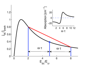
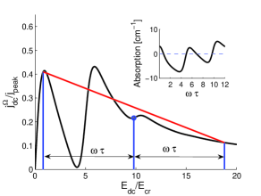
where is the maximal electron velocity in the miniband and () are the modified Bessel functions. This temperature dependence of dc current is in a good agreement with the experiment allen90 . The dependence of on is shown in Fig. 1. Instead of the field strength variable , the Esaki-Tsu characteristic can be represented in terms of Bloch frequency using the equality . For the Bloch frequency belongs to THz frequency range Esaki .
The dc differential conductivity, , defines the slope of VI characteristic at the working point. For the Esaki-Tsu dependence (3) it is
| (4) |
If , is negative and therefore Esaki-Tsu characteristic demonstrates NDC.
II.1 Small-signal gain and electric instability in dc biased superlattices
We start with the consideration of small-signal gain in dc-biased superlattice (2). In this case, the analytic calculation of absorption gives the well-known formula of Ktitorov et al. KSS . However, having in mind our future treatment of SL in bi- and polychromatic fields, it is instructive to introduce here the notion of quantum derivative and briefly analyze the high-frequency gain using this tool. The absorption (1) can be represented as the quantum derivative of the Esaki-Tsu current-field dependence (3) as ignatov_q-deriv ; wacker_q-deriv ; wackerrew
| (5) |
Figure 1 demonstrates the meaning of quantum derivative (finite difference) in the case of high-frequency probe field with () and the Wannier-Stark spacing (). Geometrically, the quantum derivative represents the slope of segment with the length defined by the probe frequency . The ends of the segment belong to the Esaki-Tsu curve and their locations are determined by the choice of working point. In the quasistatic limit , we immediately get from Eq. (5) the well-known result that the absorption is proportional to the dc differential conductivity at the operation point (4). On the other hand, as is obvious from the figure, in order to provide small-signal gain in the canonic Bloch oscillator the working point must be in the NDC portion of the Esaki-Tsu characteristic.
The frequency dependence of absorption, calculated using Eqs. 5 and 3, is shown in the inset of Fig. 1. It illustrates the dispersive profile of Bloch gain at high frequencies and also the existence of negative absorption for . The frequency corresponding to the gain resonance can be most easily estimated for the choice of working point satisfying . As is obvious from the geometric meaning of Eq. (5), the maximum of gain is achieved when the left end of the red segment is located at the peak of VI characteristic. Then a simple geometrical analysis based on Fig. 1 immediately shows that the maximum of gain corresponds to the photon energy (). This gain resonance indicates a dissipative quantum nature of the Bloch gain profile: Asymmetry in the elementary acts of emission and absorption is caused by the scattering. However, one should always remember that the feasibility of high-frequency generation in the canonic Bloch oscillator is complicated by the NDC-related electric instability.
II.2 Photon-assisted peaks and large-signal gain
In the case of large amplitude of the probe field, Eq. 2, the high-frequency gain is not anymore necessarily connected to the presence of static NDC, because the ac field can open up new transport channels leading to the formation of photon-assisted peaks in VI characteristic theory_old ; unterrainer . Here the dc current can be calculated with the help of photon replicas of the Esaki-Tsu current wackerrew
| (6) |
and the formula for absorption takes the form
| (7) |
where are the Bessel functions, summation is in infinite limits, and is given by Eq. (3). We used the notation to distinguish the dc current modified by the action of ac field from the unmodified Esaki-Tsu current . Using Eq. 6 it is easy to calculate the dc differential conductivity, ,
| (8) |
where is given by the formula (4).
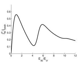
Figure 2 shows the first photon-assisted peak in the dependence of on arising under the action of strong ac field. Importantly, the left wing of the peak () is characterized by PDC. PDC exists if the Wannier-Stark spacing approximately equals to the photon energy (other words, if ).
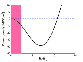
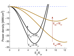
Now we want to demonstrate the feasibility of large-signal gain in conditions of static PDC. With this aim we choose the working point at the left wing of the first photon-assisted peak in Fig. 2 at () and vary the amplitude of the ac field . Absorption and, in our notations, power density will be negative if the SL can generate a high-frequency radiation. The dependence of the power density on is depicted in Fig. 3. In the same figure we also indicated the range of for which NDC is realized at the working point. We see that the generation definitely can be complicated by the existence of electric instability at small probe amplitudes: There always exists a threshold value, which the probe field amplitude must reach before SL can switch to PDC. However, if the small-signal space-charge instability can be suppressed by some way, for example by a very special SL design savvidis , the generated power density at frequency can reach (Fig. 3). For a typical semiconductor SL it corresponds to the power W.
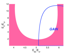
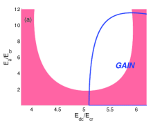
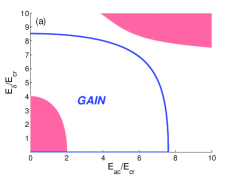
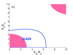
The whole ranges of bias and probe amplitudes , supporting simultaneously PDC and gain at the first photon-assisted peak, are presented in Fig. 4 for one particular value of the photon energy (). This figure shows that gain without NDC exist if and ().
Similarly, we also calculated the slope of dependence and the sign of absorption for many other probe frequencies. We summarize the requirements to obtain gain without NDC at the first photon-assisted peak as
| (9a) | |||||
| (9b) | |||||
| (9c) | |||||
The requirements (9a) and (9b) – which state that the photon energy must be larger than the scattering induced broadening and that ac field strength must be no less than two critical fields – guarantee the formation of a sharply defined photon-assisted peak. Note that in the limit opposite to Eq. (9a), the photon-assisted peaks never arise (see klapandalekseev and references cited therein). Finally, the condition (9c) ensures that simultaneously (i) the absorption is negative and (ii) the dc bias is chosen at the left wing of the photon-assisted peak corresponding to PDC . For completeness, we should also mention that PDC and gain can be simultaneously achieved also by operating close to other photon-assisted peaks (). In this case gain and modifications in the dc current density occur due to multiphoton processes, and thus larger amplitudes of the probe field are required.
We should note that a dynamical response of electrons to THz radiation can depend on details of the scattering processes leading to the relaxation towards a thermal equilibrium. In the case of SLs with a single miniband, the simple model with two different scattering constants for the electron velocity and electron energy often becomes more adequate than the approach based on a single relaxation time balance-eqs . Our numerical calculations indicate that the inequalities (9) well describe the situation for . However, a large-signal gain without NDC still can exist even if these scattering constants are very different (see Appendix A).
III Superlattice in bichromatic field
We turn to the consideration of electron transport in a SL under the action of a bichromatic ac field
| (10) |
We suppose that the ac pump is strong and the amplified probe field in general can have an arbitrary amplitude. In the case of generation, the probe field is a mode of a resonator. We assume that the frequencies and are incommensurate but both belong to THz frequency domain (, ).
In our earlier discussion, the probe field of a large amplitude induced some local structures into the VI characteristic of the SL, which eventually led to the large-signal gain without NDC. The main idea behind the bichromatic scheme of generation and amplification is to use an external ac field for the modification of VI characteristic theory_old ; unterrainer , thus making it possible to amplify even a small probe signal without NDC. We will also show that fields of large amplitude can be amplified in the same conditions as well.
III.1 Main equations
To begin with we need to calculate the dc current density and absorption for the bichromatic field (10) of arbitrary amplitudes. By using the exact formal solution of Boltzmann transport equation chambers and following earlier contribution to the formalism romanov78 , we get shorokhov ; hyart for the dc current
| (11) |
and the absorption of the probe field
| (12) |
Here the dc current density modified by the pump field alone is
| (13) |
where . Next, the dc differential conductivity can be easily calculated from Eq. (11)
| (14) |
NDC and PDC at the operation point correspond to and , respectively.
In the limit of small probe field (), we have from (11) and (12) that and
| (15) |
where is given by Eq. (13). Therefore for a weak probe both dc current and absorption are determined by VI characteristic modified by the pump field. Since the formula for small-signal gain in the bichromatic case (15) resembles the corresponding formula (5) after the substitution , we can directly extend the simple geometric analysis of sec. II.1 to the case of more complicated modifications of VI characteristic caused by the action of strong ac pump.
III.2 Small-signal analysis: Basic ideas
We want to show how to achieve a high-frequency gain working at parts of modified VI characteristic with positive slopes. With this aim we choose ac pump with large amplitude () and high frequency (). For such pump fields new local structures in VI characteristic become most pronounced and simple analytic formulas describing the modifications of dc current and gain can be derived. Figure 5 illustrates the dependence of the dc current density on the dc bias which has been calculated using Eq. (13) for () and . Additionally to the modified Esaki-Tsu peak one can see two new photon-assisted peaks. The peaks of the current are centered at
| (16) |
with . The left wings of the photon-assisted peaks ( and ) have positive slope, i.e. PDC. We found that PDC arises if the Wannier-Stark spacing approximately equals to the energy of one photon () or to the energy of two photons (). In a more general case the necessary condition for PDC becomes
| (17) |
The choice of the operation point at these parts of VI should prevent the development of space-charge instability typical for systems with NDC. For example, in Fig. 5 we choose the working point at the left part of second photon-assisted peak.
Following Eq. (15) the calculation of high-frequency absorption of a weak field requires the finding of quantum derivative of at the working point . The geometric meaning of the quantum derivative, which is evident from Fig. 5, is similar to the one described in sec. II.1. Importantly, the slope of (red online) segment, which is determining the quantum derivative, can be negative for many providing gain for these frequencies (Fig. 5).
It is easy to see that gain has a maximum if the left end of the segment is located at one of the dc current peaks. Taking into account that for high frequencies the segment has a small slope and the peaks are centered at given by Eq. (16), we get that the gain resonances exist for the values of bias and probe frequency satisfying (). In terms of photon energies and Wannier-Stark spacing, this condition for the gain resonances takes the form
| (18) |
The inset of Fig. 5 shows the absorption as a function of for , and . The gain profile demonstrates two distinct gain resonances at and , which are well described by Eq. (18) with and .
The dispersive gain profile and the locations of gain maxima indicate that from a pure quantum perspective, the gain in the dc-ac-driven SL originates from scattering-assisted transitions between quantum mechanical states. In contrast to the Bloch gain profile in a pure dc-biased SL, the photon sidebands also play their role here.
An interesting question is how the dispersive shape of gain profile in dc-ac-driven SL is sensitive to the amplitude and frequency of the pump field. Within the geometrical representation of the quantum derivative a crossover from gain to absorption corresponds to the movement of the end of the virtual segment from peak to dip in VI characteristic. Therefore one can expect that the dispersive shape of the absorption profile near this crossover is universal as long as well pronounced local structures in VI do exist. Our numerical calculations indeed demonstrate that in the vicinity of the crossover point, which also includes the gain resonance, the gain profile remains almost unaltered.
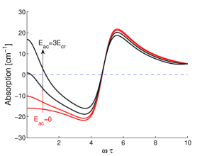
Figure 6 shows the small-signal absorption as a function of for different amplitudes of the pump, , with the high frequency . We choose the operation point . If the ac pump is strong enough, this operation point belongs to the first photon-assisted peak with PDC (see Fig. 5, where ). For all amplitudes the dispersive Bloch gain profile at high-frequencies is maintained together with with the gain resonance at the photon energy . However, with increasing pump amplitude the low-frequency absorption changes from negative to positive; the switch from NDC to PDC takes place at . Although the electric stability is achieved by a drastic change in the low-frequency absorption, there is practically no expense in the high-frequency gain.
To have an analytic formula describing the requirements for the existence of Bloch gain at PDC in dc-ac-driven SL, we directly combine the condition for PDC (17) with the formula for gain resonances (18), and get an inequality . It can be rewritten as
| (19) |
where the index () marks the -th range of gain in the absorption profile. We observed numerically that this naive estimate works surprisingly well for high-frequency pump fields with amplitudes . Here the underlying physics is the robustness of gain profile at high frequencies with its simultaneous sensitivity to variations of the pump field at low frequencies.
III.3 General conditions for gain: signals of arbitrary amplitude and positive dc conductivity
We want to show how to extend our analysis to the case of probe field which is not weak anymore. Our computations demonstrate that for parameters satisfying the small-signal gain resonance, the large-signal gain as a rule also exists. Moreover, we found that the gain profile near gain resonances stays almost unaltered as the probe amplitude changes. Furthermore, the important condition (19) works also at large amplitudes of the probe field. However, simultaneously the analog of Eq. (17) for the probe field must be also introduced: Wannier-Stark spacing is approximately equal to an integer multiple of the photon energies at the probe frequency, .
Now we can summarize our findings and list all necessary requirements to be satisfied in order to use the bichromatic scheme for a generation of high-frequency field under conditions of electric stability.
| (20a) | |||||
| (20b) | |||||
| (20c) | |||||
| (20d) | |||||
| (20e) | |||||
| (20f) | |||||
where in general integers , , and are different. Some of these inequalities, like for example (20b) and (20c), are of course same as derived earlier and here are listed for completeness. We should note these conditions are asymptotic and work better the larger is the amplitude (Eq. 20b) and the higher are the frequencies (Eqs. 20a, 20d).
The requirements (20a-20c) are necessary for the amplification of a weak probe field at an incommensurate frequency in conditions of PDC. They ensure that the operation point is located at the part of well-defined -th photon-assisted peak having a positive slope. In order the probe field still can be amplified even if its amplitude is not small anymore, the requirements (20d-20f) should be taken into an account. Below we will demonstrate how the requirements (20) work in the cases of THz generation at the first and second photon-assisted peaks. The effect of different relaxation constants, , is analyzed in Appendix A.
III.3.1 Gain and generated power density at the first photon-assisted peak
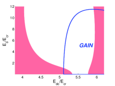
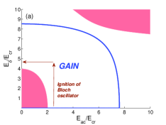
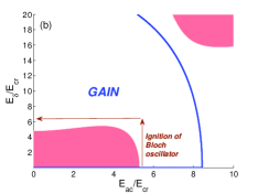
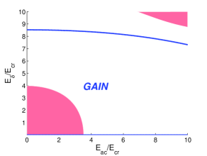
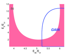
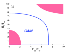
Figure 7 shows the regions of gain and NDC for different values of dc bias and probe amplitude , when the pump amplitude is fixed (cf. Fig. 4). It demonstrates the possibility to achieve simultaneously PDC and gain at the first photon-assisted peak [ in Eqs. (20)] for the probe frequency in the proximity of the pump frequency [ in Eqs. (20)]. In this figure we choose a relatively low amplitude of the pump , which is close to the threshold amplitude [see Eq. (20b)]. As a consequence, PDC for exists for , what is a bit narrower than the range following from Eq. (20c). On the other hand, figure 8a shows the regions of gain and NDC in the plane - for a fixed dc bias. It demonstrates that gain in conditions of PDC exists for the pump amplitudes , when requirements of Eqs. (20) are satisfied.
Figure 9 shows that the generated power density at the first photon-assisted peak in the bichromatic scheme slightly decreases with an increase in the pump amplitude but still remains comparable with the power density which can potentially be generated in the canonic Bloch oscillator (cf. Fig. 3). Moreover, a comparison of Fig. 6 and Fig. 1(inset) allows to make similar statement concerning the magnitudes of gain in these two schemes.
III.3.2 Generation with frequency shifting
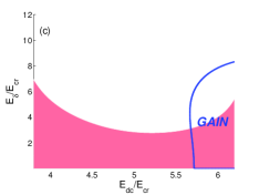
By applying a very strong pump field it is possible, due to multiphoton processes, to exploit other photon-assisted peaks and reach the generation at frequencies significantly different from the pump frequency. In the case of second photon-assisted peak ( in Eq. (20c)), the frequency of the probe field can be easily shifted from the pump frequency so that the photon energy will be close to the gain resonance , corresponding to in (20f). On the other hand, the requirement (20e) can be satisfied for by tuning dc bias. Therefore, for enough high frequency of the pump all requirements (20) are satisfied, and amplification of the probe field with both small and large amplitudes can be achieved in conditions of PDC. Figures 5, 8b, and 9 demonstrate this kind of possibilities for the pump frequency and dc bias .
IV THz starter for Bloch oscillator
It is easy to notice that the large-signal gain in conditions of PDC is realized at the same parameters of probe fields in both the monochromatic and bichromatic schemes of amplification. Good illustration of this comes from the comparison of figures 4 and 7. They show the regions of gain and PDC in these two different schemes for the same photon energy of the probe field . In both cases the regions of gain and PDC overlap approximately for dc bias values and probe amplitudes . However, in the bichromatic case there also exists an additional overlap region at small probe amplitudes for due to the formation of photon-assisted peak induced by the action of ac pump.
In more general case, we can compare the requirements (9) and (20). Assuming that the probe frequency and dc bias satisfy conditions (9a) and (9c), we immediately see that the conditions (20d) and (20e with ) are also satisfied. Moreover, the rest of requirements (20) can be satisfied with a proper choice of the pump field.
Therefore it is potentially possible to combine both these schemes in a single device. The process of domain-free generation in a resonator with very high- will include two stages: In the first stage, the ac pump is used to excite the field mode with an amplitude (requirement (9a)). In the second stage, the pump field is gradually switched off and sustained generation is performed at a large amplitude of . We underline that here the whole switching off process takes place in conditions of strong gain and PDC. Figure 8 illustrates these two stages of generation utilizing the first (a) and second (b) photon-assisted peaks. Arrows show a safe pass around the dangerous NDC region in the plane -, which corresponds to the ignition of canonic Bloch oscillator.
Since the pump ac field is needed only to the initial stage in order to suppress the formation of electric domains, and it is then switched off, it seems reasonable to use THz pulse instead of CW field in this THz starter for Bloch oscillator. The required high-power pulses of ns - s duration can be generated, for instance, with the help of free-electron laser or -laser.
A quite different situation arises when few-cycle THz pulses are in use. The field cannot be considered as a monochromatic anymore. Therefore now we will analyze the feasibility of gain in the case of polychromatic ac pump. For simplicity, we consider the case of trichromatic field
| (21) | |||||
The amplified probe field continues to be monochromatic . We suppose that the pump , , and probe, , frequencies satisfy the generalized incommensurability condition. Namely, we assume that there does not exist any nontrivial integers () such that . The equation (21) can be considered as a crude approximation for the temporal shape of a real broadband THz pulse, where the Fourier transform of the pulse has a maximum at and is related to the bandwidth of the pulse.
The analysis of previous sections can be directly generalized to the case of polychromatic pump field (21), and we get for dc current density
| (22) |
and for absorption of the probe field
Here is dc current density in SL modified by the pump field alone
| (24) | |||||
Equations (22) and (LABEL:incohabstri) are valid for an arbitrary amplitude of the probe field. Remarkably, in the limit of weak probe field (), the absorption becomes proportional to the quantum derivative of the pump-modified dc current (24).
In the limit () the trichromatic pump field (21) becomes momochromatic and therefore one would expect a restoration of all results of section III. However that is not the case, and the current density and absorption, given by the equations (22) and (LABEL:incohabstri), are not reduced to the corresponding equations of section III. The disagreement arises because the condition of incommensurability is not satisfied in this limit.
We computed the regions of NDC and gain for the pump (21) with two different side frequencies and , when the cental frequency determines the first photon-assisted peak in VI characteristic. Figure 10 shows the regions of gain and PDC in the - plane. The Wannier-Stark spacing and photon energies (, and ) are the same as used in figure 8a. By comparing figures 8 and 10, one observes that the gain and PDC can be achieved in both cases at similar amplitudes of the probe field, while a bit larger pump is required in the trichromatic case.
These results support the possibility to replace a monochromatic pump with a broadband THz pulse in the starter for Bloch oscillator. Required intensive T-rays can be produced by a number of ways, including the use of interdigitated photoconducting device T-rays1 , amplifier systems T-rays2 or from ultrafast ionizing air T-rays2 (for recent review, see T-rays-rev ).
V Conclusion
We theoretically analyzed the feasibility to reach THz gain in dc-biased semiconductor superlattice at room temperature using mono- and polychromatic alternating pump fields. We showed that different kinds of pump fields can suppress the formation of high-field electric domains inside the superlattice while still preserve a broadband THz gain at frequencies incommensurate with the pump frequencies.
Our approach is based on the utilization of well-known photon-assisted peaks theory_old ; unterrainer arising in the voltage-current characteristics of THz-driven superlattices. Choice of the operation point at the positive slope of such peak allows to suppress the electric instability. For the search of high-frequency gain in conditions of the positive differential conductivity we employed simple but powerful geometric interpretations of the intraminiband absorption formulas. Combining these analytic tools and numerical simulations, we demonstrated that the Bloch gain profile in dc-ac-driven superlattice is robust near the gain resonances.
We suggested to use the robustness property of THz gain in an effective starter for the canonic (only dc-biased) Bloch oscillator operating in the electrically stable large-amplitude mode of generation Kroemer . Since THz gain in both the canonic Bloch oscillator and dc-ac-pumped Bloch oscillator occurs in the same ranges of dc bias, generation frequency and amplitude, a temporal application of the ac pump field can be used for domain-free generation up to the amplitude, which becomes sufficient for a stable operation of the canonic Bloch oscillator. The pump field, which ignites the Bloch oscillator, can also be polychromatic. We predicted that available intensive, broadband THz pulses (T-rays) can potentially be used in the fast ignition of Bloch oscillator.
We conclude with two remarks. First, in this work we limit our attention to the case of incommensurate frequencies. If the pump and probe frequencies are commensurate, an additional coherent term in the formulas for high-frequency absorption will arise Hyart2007 . The sign of the term depends on the value of relative phase between the pump and amplified fields Hyart2007 ; Hyart2006 . However, at least in the case of generation with the monochromatic pump field, the coherent term always contributes to the high-frequency gain. A more detailed analysis of this situation, including a consideration of microwave and sub-THz pump fields Alekseev2006 ; romanov-jap06 , will be presented elsewhere.
Second, we have focused on the local modification of voltage-current characteristics of superlattices arising when the Bloch frequency approaches the ac field frequency or its harmonics. However, similar modifications of the electric characteristics have been observed in the semiconductor superlattices subject to the tilted high magnetic field, when the Bloch frequency is close to the cyclotron frequency or its harmonics fromhold . It is very interesting problem to consider modifications of the voltage-current characteristics bass-magnetic and analyze the feasibility of THz gain in a superlattice under the combined action of tilted magnetic and alternating electric fields.
Acknowledgements.
We thank Ahti Leppänen for cooperation, Andreas Wacker for attraction out attention to ref. wacker_q-deriv, and Amalia Patane, Alexander Balanov, Miron Kagan, Alvydas Lisauskas, Jussi Mattas, Hartmut Roskos, Harald Schneider, Alexey Shorokhov, Gintaras Valušis, Stephan Winnerl for useful discussions. We are grateful to Feodor Kusmartsev for advices and constant encouragement of this activity within EU programme. This research was partially supported by Emil Aaltonen Foundation, Academy of Finland (101165, 109758), Magnus Ehrnrooth Foundation, Väisälä Foundation, and AQDJJ Programme of European Science Foundation.Appendix A Effect of elastic scattering
Here we consider the effects of different scattering constants in both the monochromatic (2) and bichromatic (10) schemes of THz amplification and generation. The following SL balance equations can be derived from the Boltzmann transport equation for a single miniband of SL balance-eqs ; wackerrew
| (25) |
where is the current density and is the total energy density of electrons within the miniband, and are the phenomenological scattering constants for electron energy and miniband electron velocity, is the scattering constant describing elastic scattering events. All electrons are at the bottom of miniband for and the upper edge of miniband is reached if . The average electron energy in thermal equilibrium depends on the lattice temperature wackerrew . It is convenient to introduce the mean scattering time and ratio of scattering constants . According to many experiments Schomburg is a good assumption, although it is not valid for all superlattices Hirakawa .
Solving numerically the SL balance equations (25), we determine the time-dependence of a steady current for and then calculate the dc differential conductivity and absorption of the probe field. In the case , we find an excellent agreement with the earlier analytic results following from the formulas (7), (8), and (12), (14). We observe that the photon-assisted peaks occur in VI characteristics for all values of ; however, with a decrease in the ratio these VI structures become less pronounced and magnitudes of high-frequency gain are decreasing.
Importantly, the amplification still occurs in approximately the same ranges of field amplitudes for different values of . Figure 11 represents the ranges of dc bias and ac pump amplitude , supporting large-signal gain with PDC at the first photon-assisted peak induced by the monochromatic field (2). With decreasing the range of amplitudes for negative absorption shrinks but the range of amplitudes supporting PDC expands (cf. subplots in Fig. 11). The changes are obviously small as long as . Figure 12 shows the ranges of pump and probe field amplitudes supporting a generation at the first photon-assisted peak in the bichromatic scheme. The suppression of electric domains and the absorption in the bichromatic field (10) are based on the same physical phenomena. Therefore the decrease in affects the bichromatic scheme in a similar way as in the mochromatic case.
References
- (1) Special issue of Proc. IEEE 80, No 11 (2002); P. H. Siegel, IEEE Trans. Microwave Theory and Techiques 50, 910 (2002); B. Ferguson and X.-C. Zhang, Nature Materials 1, 26 (2002); Special issue of Phil. Trans. R. Soc. London A 362, No 1815 (2004); M. Tonouchi, Nature Photonics 1, 97 (2007).
- (2) R. Köhler, A. Tredicucci, F. Beltram, H. E. Beere, E. H. Linfield, A. G. Davies, D. A. Ritchie, R. C. Iotti, and F. Rossi, Nature 417, 156 (2002).
- (3) S. Kumar, B. S. Williams, S. Kohen, Q. Hu, and J. L. Reno Appl. Phys. Lett. 84, 2494 (2004); B.S. Williams, S. Kumar, Q. Hu, and J. Reno, Opt. Express 13, 3331 (2005).
- (4) L. Esaki and R. Tsu, IBM J. Res. Dev. 14, 61 (1970).
- (5) F. G. Bass and A. P. Tetervov, Phys. Rep. 140, 237 (1986).
- (6) A. Wacker, Phys. Rep. 357, 1 (2002).
- (7) G. Platero and R. Aguado, Phys. Rep. 395, 1 (2004).
- (8) F. Bloch, Z. Phys. 52, 555 (1928).
- (9) C. Zener, Proc. R. Soc. A 145, 523 (1934).
- (10) K. Leo, P. H. Bolivar, F. Bruggemann, R. Schwedler, and K. Köhler, Solid State Commun. 84, 943 (1992); J. Feldmann, K. Leo, J. Shah, D. A. B. Miller, J. E. Cunningham, T. Meier, G. von Plessen, A. Schulze, P. Thomas and S. Schmitt-Rink, Phys. Rev. B 46, 7252 (1992); T. Dekorsy, P. Leisching, K. Köhler, and H. Kurz, Phys. Rev. B 50, 8106 (1994).
- (11) S. A. Ktitorov, G. S. Simin, and V. Ya. Sindalovskii, Fiz. Tverd. Tela 13, 2230 (1971) [Sov. Phys. Solid State 13, 1872 (1972)].
- (12) Yu. A. Romanov, V. P. Bovin and L. K. Orlov, Fiz. Tekhn. Polupr. 12, 1665 (1978) [ Sov. Phys. Semicond. 12, 987 (1978)].
- (13) A. A. Ignatov, K. F. Renk, and E. P. Dodin, Phys. Rev. Lett. 70, 1996 (1993).
- (14) H. Kroemer, cond-mat/0007482; E. Schomburg, N. V. Demarina and K. F. Renk, Phys. Rev. B 67, 155302 (2003).
- (15) H. Willenberg, G. H. Döhler and J. Faist, Phys. Rev. B 67, 085315 (2003); A. Wacker, Phys. Rev. B 66, 085326 (2002).
- (16) R. Terazzi, T. Gresch, M. Giovannini, N. Hoyler, N. Sekine, and J. Faist, Nature Physics, 3, 329 (2007).
- (17) J. B. Gunn, Solid State Comm. 1, 88 (1963); J. B. Gunn, IBM J. Res. Dev. 8, 141 (1964).
- (18) M. Büttiker and H. Thomas, Phys. Rev. Lett. 38, 78 (1977); A. A. Ignatov and V. I. Shashkin, Zh. Eksp. Teor. Fiz. 93, 935 (1987) [Sov. Phys. JETP 66, 526 (1987)].
- (19) H. Le Person, C. Minot, L. Boni, J. F. Palmier, and F. Mollot, Appl. Phys. Lett. 60, 2397 (1992); K. Hofbeck, J. Grenzer, E. Schomburg, A. A. Ignatov, K. F. Renk, D. G. Pavel’ev, Yu. Koschurinov, B. Melzer, S. Ivanov, S. Schaposchnikov, and P. S. Kop’ev, Phys. Lett. A 218, 349 (1996).
- (20) H. Kroemer, cond-mat/0009311.
- (21) J. Copeland, J. Appl. Phys. 38, 3096 (1967).
- (22) I. V. Altukhov, M. S. Kagan, S. G. Kalashnikov, V. V. Kukushkin, and , V. N. Solyakov, Fiz. Tekhn. Polupr. 13, 2316 (1979) [ Sov. Phys. Semicond. 13, 1356 (1979) ].
- (23) V. N. Sokolov, K. W. Kim, V. A. Kochelap, and D. L. Woolard, J. Appl. Phys. 98, 064507 (2005).
- (24) P. G. Savvidis, B. Kolasa, G. Lee, and S. J. Allen, Phys. Rev. Lett. 92, 196802 (2004).
- (25) A. Lisauskas, C. Blöser, R. Sachs, H. G. Roskos, A. Juozapavičius, G. Valušis, and K. Köhler, Appl. Phys. Lett. 86, 102103 (2005).
- (26) N. Sekine and K. Hirakawa, Phys. Rev. Lett. 94, 057408 (2005).
- (27) T. Kurosawa and S. Nagahashi, J. Phys. Soc. Japan 45, 707 (1978); A. A. Ignatov, Doklady Akademii Nauk SSSR 273, 1351 (1983) [Soviet Physics Doklady 28, 1046 (1983)].
- (28) T. Feil, R. A. Deutschmann, W. Wegscheider, M. Rother, D. Schuh, M. Bichler, G. Abstreiter, B. Rieder, and J. Keller, Phys. Stat. Sol. C 1, 21112130 (2004).
- (29) E. S. Daniel, B. K. Gilbert, J. S. Scott, and S. J. Allen, IEEE Trans. Electron. Devices 50, 2434 (2003).
- (30) T. Feil, H.-P. Tranitz, M. Reinwald, and W. Wegscheider, Appl. Phys. Lett. 87, 212112 (2005); T. Feil, C. Gerl, and W. Wegscheider, Phys. Rev. B 73, 125301 (2006).
- (31) Yu. A. Romanov, L. G. Mourokh, and N. J. M. Horing, J. Appl. Phys. 93 4696 (2003); G. M. Shmelev, I. I. Maglevanny, and E. M. Epshtein, arXiv:0705.1910; M. L. Orlov, Yu. A. Romanov, and L. K. Orlov, Microelectronics Journal 36, 396 (2005).
- (32) D. A. Ryndyk, N. V. Demarina, J. Keller, and E. Schomburg, Phys. Rev. B 67, 033305 (2003).
- (33) For the theory, see V. V. Pavlovich and É. M. Épshteǐn, Fiz. Tekh. Polupr. 10, 2001 (1976) [Sov. Phys. Semicond. 10, 1196 (1976)]; F. G. Bass and E. A. Rubinshtein, Fiz. Tverd. Tela 19, 1379 (1977) [ Sov. Phys. Solid State 19, 800 (1977) ].
- (34) For the experiment, see K. Unterrainer, B. J. Keay, M. C. Wanke, S. J. Allen, D. Leonard, G. Medeiros-Ribeiro, U. Bhattacharya, and M. J. W. Rodwell, Phys. Rev. Lett. 76, 2973 (1996).
- (35) K. Reimann, Rep. Prog. Phys. 70, 1597 (2007).
- (36) R. G. Chambers, Proc. Phys. Soc. (London) A 65, 458 (1952); H. Budd, Phys. Rev. 127, 4 (1962); C. MacCallum, Ibid 132, 930 (1963).
- (37) G. Brozak, M. Helm, F. DeRosa, C. H. Perry, M. Koza, R. Bhat, and S. J. Allen, Phys. Rev. Lett. 64, 3163 (1990).
- (38) A. A. Ignatov, E. Schomburg, J. Grenzer, S. Winnerl, K. F. Renk, and E. P. Dodin, Superlatt. Microstr. 22, 15 (1997).
- (39) A. Wacker, S. J. Allen, J. S. Scott, M. C. Wanke, and A.-P. Jauho, Phys. Stat. Sl. B 204, 95 (1997).
- (40) F. Klappenberger, K. N. Alekseev, K. F. Renk, R. Scheuerer, E. Schomburg, S. J. Allen, G. R. Ramian, J. S. S. Scott, A. Kovsh, V. Ustinov and A. Zhukov, Eur. Phys. J. B 39, 483 (2004).
- (41) A. A. Ignatov and Yu. A. Romanov, Phys. Stat. Sol. B 73, 327 (1976); A. A. Ignatov, E. P. Dodin and V. I. Shashkin, Mod. Phys. Lett. 5, 1087 (1991).
- (42) A. V. Shorokhov and K. N. Alekseev, Physica E 33, 284 (2006).
- (43) T. Hyart, M. Sc. Thesis, University of Oulu, 2005.
- (44) A. Dreyhaupt, S. Winnerl, M. Helm, and T. Dekorsy, Opt. Lett. 31, 1546 (2006).
- (45) T. Bartel, P. Gaal, K. Reimann, M. Woerner, and T. Elsaesser, Opt. Lett. 30, 2805 (2005);
- (46) K.-Y. Kim, J. H. Glownia, A. J. Taylor, and G. Rodriguez, Opt. Express 15, 4577 (2007).
- (47) T. Hyart, A. V. Shorokhov, and K. N. Alekseev, Phys. Rev. Lett. 98, 220404 (2007).
- (48) T. Hyart, N. V. Alexeeva, A. Leppänen, and K. N. Alekseev, Appl. Phys. Lett. 89, 132105 (2006).
- (49) K. N. Alekseev, M. V. Gorkunov, N. V. Demarina, T. Hyart, N. V. Alexeeva, and A. V. Shorokhov, Europhys. Lett. 73, 934 (2006); 74, 567(E) (2006).
- (50) Yu. A. Romanov, J. Yu. Romanova, and L. G. Mourokh, J. Appl. Phys. 99, 013707 (2006).
- (51) T.M. Fromhold, A. Patane, S. Bujkievicz, P.B. Wilkinson, D. Powler, D. Sherwood, S.P. Stapleton, A.A. Krokhin, L. Eaves, M. Henini, N.S. Sankeshwar, and F.W. Sheard, Nature 428, 726 (2004).
- (52) F. G. Bass, V. V. Zorchenko, and V. V. Shashora, Pis’ma Zh. Eksp. Teor. Fiz. 31, 345 (1980) [JETP Lett. 31, 314 (1980)].
- (53) E. Schomburg, T. Blomeier, K. Hofbeck, J. Grenzer, S. Brandl, I. Lingott, A. A. Ignatov, K. F. Renk, D. G. Pavel’ev, Yu. Koschurinov, B. Ya. Melzer, V. M. Ustinov, S. V. Ivanov, A. Zhukov, and P. S. Kop’ev, Phys. Rev. B 58, 4035 (1998).