The ALICE Forward Multiplicity Detector
Abstract
The ALICE Forward Multiplicity Detector (FMD) is a silicon strip detector with 51,200 strips arranged in 5 rings, covering the range . It is placed around the beam pipe at small angles to extend the charged particle acceptance of ALICE into the forward regions, not covered by the central barrel detectors.
1 Motivation and purpose
Experiences from RHIC have shown, that of interesting physics is happening not only in the central rapidity region of A+A collisions, but also at higher values of pseudo–rapidity. In particular, the BRAHMS collaboration has measured particle distributions and ratios, high suppression, and spectra at very forward rapidity, and obtained important information about the initial state of the colliding nucleons (the colour glass condensate)[1, 2].
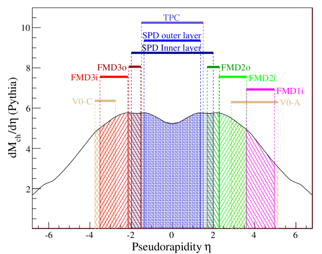
The ALICE Forward Multiplicity Detector[3] (FMD) provides a high resolution charged particle multiplicity determination at very forward rapidity, which allows ALICE to give a more complete picture of the bulk properties of the interactions in A+A collisions. The FMDs coverage does not extend all the way into the fragmentation region in Pb+Pb collisions, but the extended overall shape of the charged particle multiplicity distribution can help differentiate between different scenarios[4, 5, 6, 7, 8] for the A+A collisions.
Likewise, the measurement of anisotropic azimuthally flow [9] at RHIC has proved to be an extremely useful tool in characterising the ultra–relativistic heavy ion collisions[10, 11, 12, 13]. The measurement of requires a good and reliable measurement of the event planes inclination from the horizontal plane [14].
The ALICE Forward Multiplicity Detector provides measurements of the charged particle multiplicity in the forward regions and , measurement of the event planes inclination, as well as an independent measurement of . Other kinds of charged particle multiplicity analysis, such as fluctuations in particle number, can also be extended to cover larger regions by using the FMD.
2 The Detector
The FMD is a silicon strip detector of modest segmentation. It is made of 5 rings FMD1i, FMD2i, FMD2o, FMD3i, and FMD3o, placed around the beam pipe. The rings consists of 10 (for the inner rings, FMD1i, FMD2i, and FMD3i) or 20 (for the outer rings FMD2o, FMD3o) hexagonal silicon sensors cut out of thick silicon 6” wafers. Each sensor is azimuthal segmented into 2 sectors, and each sector is segmented into strips at constant radii. The segmentation gives a total of 51,200 read-out channels (or strips).
Fig. 2 shows the arrangement of sectors in the inner and outer rings, and Table 1 gives the segmentation of the various sub–detectors. Practically, the detector is assembled in half rings to allow them to be mounted around thee LHC beam pipe.

| Ring | Azimuthal | Radial | |||||
|---|---|---|---|---|---|---|---|
| sectors | strips | [cm] | range [cm] | coverage | |||
| FMD1 | 20 | 512 | 320 | 4.2 – | 17.2 | 3.68 – | 5.03 |
| FMD2i | 20 | 512 | 83.4 | 4.2 – | 17.2 | 2.28 – | 3.68 |
| FMD2o | 40 | 256 | 75.2 | 15.4 – | 28.4 | 1.70 – | 2.29 |
| FMD3i | 20 | 512 | -75.2 | 4.2 – | 17.2 | -2.29 – | -1.70 |
| FMD3o | 40 | 256 | -83.4 | 15.4 – | 28.4 | -3.40 – | -2.01 |
Mounted directly behind each sensor is a hybrid card with 8 (for the inner rings) or 4 (for the outer rings) VA1_3 preamplifier chips. The VA1_3 belongs to the time–tried Viking family of silicon preamplifier chips[15]. The VA1_3 is customised for the ALICE FMD to allow signals up to the equivalent of 20 minimum ionising particles (MIP) impinging on the silicon sensor. Each preamplifier chip reads out 128 strips, and multiplexes them into 1 differential read–out channel.
The sensor–hybrid modules are mounted on honeycomb plates for support. The modules are staggered in to minimise the dead zones in the acceptance. The failure rate of the modules has been found to be – that is, very few of the 51,200 strips have problems.
A custom developed digitiser card (FMDD) is mounted on the back side of each half–ring honeycomb support plates. On the FMDD are three 16 channel ALTRO[16] ADC chips. One read–out channel of the VA1_3 preamplifier chip is connected to one ALTRO channel. As such, each ALTRO channel reads out 128 strips. The basic design of the FMDD is based on the TPC front end card, but customised to the specific needs of the FMD. For example, the FMD requires additional trigger handling on the front-end not present on the TPC front end card.
The ALTRO ADC is a custom chip developed for the ALICE TPC read-out system. It is a very advanced chip with many options for speeding up the read-out and have the front-end do first-level data processing. The ALTRO was chosen for the FMD, since it provides a fast parallel read-out of many channels from the front end, is radiation tolerant, and because it is highly customisable.
The FMDD has a Board Controller (BC), implemented in an FPGA, to control the communication with the back-end of the read-out chain, monitor the status of the electronics, control the preamplifiers, and handle triggers. The BC handles most of the tasks related to the front end electronics. It monitors that temperatures, voltages, and currents are within acceptable values, and manages calibration runs.
The read-out of the sub-detectors FMD1, FMD2, and FMD3 is managed by a Read–out Controller Unit[17] (RCU). The RCU is developed by the TPC collaboration, and controls the read out of the ALTROs. A special bus protocol has been developed to maximise the throughput of data. The RCU also provides means of communication for the detector control system to control the front–end electronics via a dedicated instruction memory. Each RCU card is fitted with an optical interface to transfer data to the data acquisition system. A daughter card with an embedded computer running Linux, provides the interface to the outside world through standard TCP/IP communication.
3 Test beam results
The nearly complete system was tested with the ASTRID[18] 650 MeV parasitical beam. The sensors where put in a row behind each other (rather than in rings) to allow maximum testing of the detector response to minimum ionising particles.
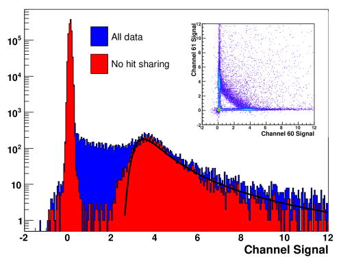
If the incident particle trajectory is not perpendicular to the plane defined by the sensors, then a particle close to the strip boundaries can deposit energy in more than one strip. This gives rise to what is known as sharing. It manifests itself as two or more adjacent strips having signals over background less than the level corresponding to a minimum ionising particle. However, the sum of the signals should corresponds to at least 1 MIP. Fig. 3 shows the distribution of signals before and after cutting away the shared hits. The insert shows the correlation plot of recorded energy in adjacent strips. The anti-correlation seen in the insert is typical of sharing.
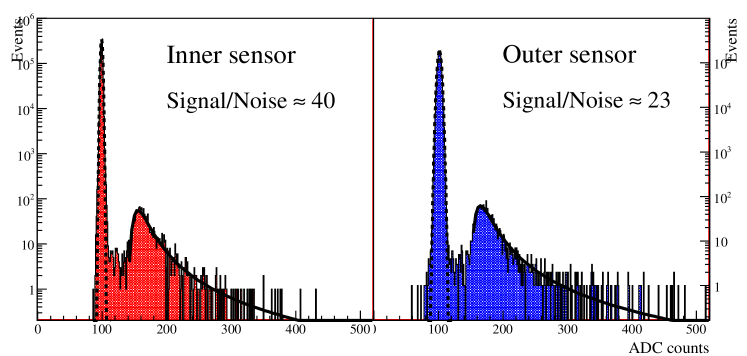
Using the final read–out system, five sensors were put in a row in the beam, and scintillators were placed before and after the sensors and the coincidence between these was used as the trigger. The resulting energy distribution is shown in Fig. 4. A signal–to–noise of for the inner type sensors, and for the outer type sensors was achieved. This is well above the Technical Design Report[3] requirement of a signal–to–noise ratio of 10:1, and close to what can be expected from basic calculations.
References
- [1] I. Arsene et al. [BRAHMS Collaboration], Phys. Rev. Lett. 93, 242303 (2004) [arXiv:nucl-ex/0403005].
- [2] I. Arsene et al. [BRAHMS Collaboration], Nucl. Phys. A 757, 1 (2005) [arXiv:nucl-ex/0410020].
- [3] [ALICE Collaboration], “ALICE technical design report on forward detectors: FMD, T0 and V0,” CERN-LHCC-2004-025.
- [4] J. D. Bjorken, Phys. Rev. D 27, 140 (1983).
- [5] L. D. Landau, Izv. Akad. Nauk Ser. Fiz. 17, 51 (1953).
- [6] S. Z. Belenkij and L. D. Landau, Nuovo Cim. Suppl. 3S10, 15 (1956) [Usp. Fiz. Nauk 56, 309 (1955)].
- [7] B. B. Back et al. [PHOBOS Collaboration], Phys. Rev. Lett. 88, 022302 (2002) [arXiv:nucl-ex/0108009].
- [8] I. G. Bearden et al. [BRAHMS Collaboration], Phys. Rev. Lett. 90, 102301 (2003).
- [9] S. Voloshin and Y. Zhang, Z. Phys. C 70, 665 (1996) [arXiv:hep-ph/9407282].
- [10] S. A. Voloshin and A. M. Poskanzer, Phys. Lett. B 474, 27 (2000) [arXiv:nucl-th/9906075].
- [11] B. B. Back et al. [PHOBOS Collaboration], Phys. Rev. Lett. 89, 222301 (2002) [arXiv:nucl-ex/0205021].
- [12] B. B. Back et al. [PHOBOS Collaboration], Phys. Rev. C 72, 051901 (2005) [arXiv:nucl-ex/0407012].
- [13] J. Adams et al. [STAR Collaboration], Nucl. Phys. A 757, 102 (2005) [arXiv:nucl-ex/0501009].
- [14] G. Wang, D. Keane, A. Tang and S. A. Voloshin, arXiv:nucl-ex/0611001.
- [15] O. Toker, S. Masciocchi, E. Nygard, A. Rudge and P. Weilhammer, Nucl. Instrum. Meth. A 340, 572 (1994).
- [16] R. Esteve Bosch, A. Jimenez de Parga, B. Mota and L. Musa, IEEE Trans. Nucl. Sci. 50 (2003) 2460.
- [17] R. Esteve Bosch et al. [ALICE Collaboration], Prepared for 8th Workshop on Electronics for LHC Experiments, Colmar, France, 9-13 Sep 2002
- [18] R. Stensgaard, Phys. Scripta T22, 315 (1988).