Light-induced rotation of dye-doped liquid crystal droplets
Abstract
We investigate both theoretically and experimentally the rotational dynamics of micrometric droplets of dye-doped and pure liquid crystal induced by circularly and elliptically polarized laser light. The droplets are dispersed in water and trapped in the focus of the laser beam. Since the optical torque acting on the molecular director is known to be strongly enhanced in light-absorbing dye-doped materials, the question arises whether a similar enhancement takes place also for the overall optical torque acting on the whole droplets. We searched for such enhancement by measuring and comparing the rotation speed of dye-doped droplets induced by a laser beam having a wavelength either inside or outside the dye absorption band, and also comparing it with the rotation of pure liquid crystal droplets. No enhancement was found, confirming that photoinduced dye effects are only associated with an internal exchange of angular momentum between orientational and translational degrees of freedom of matter. Our result provides also the first direct experimental proof of the existence of a photoinduced stress tensor in the illuminated dye-doped liquid crystal. Finally, peculiar photoinduced dynamical effects are predicted to occur in droplets in which the molecular director is not rigidly locked to the flow, but so far they could not be observed.
pacs:
42.50.Vk,42.70.Gi,61.30.Pq,61.30.GdI Introduction
It has been known since the early eighties that light can transfer its angular momentum to liquid crystals with high efficiency, causing the rotation of the average molecular orientation, as specified by the molecular director review .
In the early 90’s it was discovered that adding small amounts of certain dyes to the liquid crystals, the light-induced torque on the molecular director could be greatly enhanced Jánossy et al. (1990); Jánossy and Kósa (1992). This effect, initially rather puzzling, was later explained by a model relying on the reversible changes of intermolecular forces occurring between photoexcited dye molecules and liquid crystal host Jánossy (1994). This model was subsequently extended and refined Marrucci and Paparo (1997) and confirmed with several independent experiments Marrucci et al. (1997, 2000); Kreuzer et al. (2002, 2003); Truong et al. (2005).
The understanding achieved with this model has also provided an answer to a fundamental question related to the observed torque enhancement: where does the additional angular momentum come from? Clearly, the angular momentum that is transported by the optical wave impinging on the material cannot be affected by the presence of dye. It is true that absorption of light due to the dye does lead to some additional transfer of angular momentum from light to matter and therefore to a variation of the light-induced torque. However, this effect cannot account for the magnitude of the observed torque enhancement Marrucci et al. (1997) and for its peculiar dye-structure dependence Marrucci et al. (2000). The clearest solution to this puzzle was put forward in Refs. Marrucci and Paparo (1997) and Palffy-Muhoray and E (1998) and is as follows. The angular momentum transfer from light is indeed approximately unchanged. Light absorption however triggers a transfer of angular momentum between different internal degrees of freedom of the liquid crystal, namely from the center-of-mass molecular degrees of freedom, corresponding macroscopically to fluid flow, to the molecular-orientation degrees of freedom, corresponding to the molecular director. Being an internal transfer, the total angular momentum given to the material as a whole is not affected by the presence of dye. Another consequence of this internal transfer is that, by the force action-reaction principle, in dye-doped liquid crystals there should be another (opposite) torque acting on the fluid in the form of a photoinduced stress-tensor Marrucci and Paparo (1997).
However plausible they may be, both these predictions have never been tested directly in an experiment. Here we address these questions by studying the rotational behavior of pure and dye-doped liquid crystal droplets of micrometric size, optically trapped in water, under the effect of circularly and elliptically polarized infrared and visible laser light. In particular, we measured the rotation speed of dye-doped droplets illuminated with visible light, having a wavelength in the dye absorption domain, and compared it with that of undoped droplets and with the case in which the illumination is by infrared light, not absorbed by the dye. Should we observe some significant dye-induced enhancement (or other anomalies) of the droplet rotation speed, this would imply that the current understanding of the photoinduced torque as entirely due to an internal exchange of angular momentum is not correct, or at least not complete.
But what do we exactly mean by droplet rotation? From a theoretical point of view, a liquid crystal droplet actually has two independent rotational degrees of freedom: the average molecular director, corresponding to the average orientation of the liquid crystal molecules in the droplet, and the internal rotational flow, corresponding to a fluid-like motion of the molecule centers of mass (this is already a strong simplification: a liquid crystal droplet has actually an infinite number of rotational degrees of freedom associated with changing inhomogeneous configurations of director and flow). These two rotational degrees of freedom of the droplet are always strongly interacting with each other, via viscosity, elastic forces, and possibly also photoinduced effects. This interaction may be strong enough to lock the two degrees of freedom together into a single one, so that the droplet effectively behaves as a rigid body. This is what we actually observed in our experiments. Nonetheless, by properly choosing the experimental parameters, it should be possible to reach a regime in which the two rotational degrees of freedom become effectively unlocked. We would expect that in this “unlocked” regime, photoinduced dye effects become important, even if the angular momentum exchange is entirely internal. We investigated theoretically this case and predicted the occurrence of highly non-trivial photoinduced rotational effects, which we then tried to observe experimentally.
This article is organized as follows. The general continuum theory of the light-induced dynamics of dye-doped liquid crystals is reviewed in Sec. II. In Sec. III, we then apply this theory to the case of a spherical droplet immersed in water. With the help of several strongly-simplifying approximations, analytical solutions are found, predicting what should be the light-induced rotational behavior of the droplets as a function of light power and polarization and of droplet size. Our experiments are then described and discussed in Sec. IV. Our results are finally summarized in Sec. V.
II General theory of photoinduced dynamics of nematics
II.1 Dynamical fields and equations
In general, the dynamics of a nematic liquid crystal under the action of laser light is defined by the temporal and spatial dependence of the following fields: (i) the molecular director specifying the local average molecular alignment footnote1 , (ii) the velocity vector defining the flow of matter, and (iii) the electric and magnetic fields of the optical wave, and , respectively.
The optical fields and are governed by the usual electromagnetic Maxwell equations in (anisotropic) dielectric media Landau and Lifschitz (1984). The two material fields and are respectively governed by the director torque balance equation,
| (1) |
and by the Newton equation for the acceleration (or momentum conservation law),
| (2) |
where stands for the partial derivative and the usual sum convention over repeated indices is understood. In these equations, is the total torque density acting on the molecular director, is the total stress tensor associated with a fluid displacement with no director rotation (this corresponds to Ericksen’s definition of stress tensors in liquid crystals de Gennes and Prost (1993)), is a moment of inertia per unit volume associated with the rotation of the nematic director, which is actually negligible in all practical cases (it is included only for making the equation physical meaning clearer), and is the mass density, hereafter assumed to be constant (incompressible fluid approximation). Moreover, in both equations above we have used the so-called “material” or “convective” time derivative, defined as , corresponding to a derivative taken following the fluid element along its motion. Incompressibility actually adds the following constraint on the velocity field :
| (3) |
which is a particular case of the mass continuity equation.
II.2 Constitutive equations
Equations (1) and (2) are to be completed with the appropriate constitutive equations for the total torque density and stress tensor. To first order in all deviations from equilibrium and in all gradients, we may distinguish five additive and independent contributions to both the torque density and the stress-tensor de Gennes and Prost (1993); Chandrasekhar (1992): hydrostatic pressure (hp), elastic (el), viscous (vis), electromagnetic (em), and photoinduced (ph), the latter being that associated with dye effects. In summary, one may write
| (4) |
and
| (5) |
Each of the ten and () terms appearing in these two equations has a well defined (first-order) constitutive dependence on the dynamical fields, which we will now briefly discuss.
First, there is actually no torque density associated to pressure effects, i.e., identically. The hp stress tensor term has instead the usual simple form , where is the pressure field and is the Kronecker delta. In the incompressible-fluid approximation we are adopting, must be treated as a pure “constraint force”, i.e., assuming just the space and time dependence needed to ensure continuous validity of Eq. (3).
Next, the constitutive laws of the elastic and viscous torque densities and stress-tensors are fully standard and we refer to Refs. de Gennes and Prost (1993) or Chandrasekhar (1992) for their explicit expressions.
Let us now turn to the electromagnetic terms. They are also standard, but it is nevertheless convenient to introduce them explicitly here. We assume for the time being that the electromagnetic fields present in our systems are associated only with an approximately monochromatic optical wave having a given vacuum wavelength . Let us first introduce the uniaxial optical dielectric tensor of the liquid crystal
| (6) |
where is the vacuum dielectric constant, the relative dielectric constant for and the relative dielectric anisotropy. Neglecting all magnetic effects at optical frequencies, the electromagnetic torque density is then given by
| (7) |
where is the usual dielectric displacement field () and where denotes a time average over an optical cycle. The electromagnetic stress tensor can be written in the following form Landau and Lifschitz (1984); footnote2 :
| (8) |
where is the vacuum magnetic permittivity constant and is the electromagnetic free energy density at given electric field and magnetic field strength , which in our case can be written as
| (9) | |||||
Let us finally consider the photoinduced terms, i.e., those appearing in dye-doped liquid crystals when illuminated with light having a wavelength falling within the dye absorption band. These are absolutely nonstandard. In the limit of small light intensities, simple symmetry arguments show that the photoinduced torque density must be identical to the electromagnetic one except for the replacement of the dielectric anisotropy with a new material constant , proportional to the absorbance (or to dye concentration) Marrucci and Paparo (1997). Therefore, its explicit expression can be written as follows:
| (10) |
(the constant is inserted for making dimensionless). Similarly, we may apply symmetry arguments for identifying the most general possible expression of the photoinduced stress tensor. This expression contains seven new unknown material constants (all proportional to the absorbance):
| (11) | |||||
The effects of this stress tensor have never been measured or even detected in ordinary liquid crystals, although related photoinduced effects may have been observed in polymeric nematic elastomers Finkelmann et al. (2001); Yu et al. (2003).
II.3 Angular momentum conservation
Before moving on to the specific case of a droplet of liquid crystal immersed in water, it is convenient to see how the law of angular momentum conservation enters our problem.
In contrast to the case of the conservation of (linear) momentum, which provides an additional dynamical equation, the law of angular momentum conservation actually sets only a general constraint on the possible constitutive laws of torque densities and stress tensors. For any given volume of material, the corresponding angular momentum rate of change will be given by the following law:
| (12) |
where is the total angular momentum within volume and is the total external torque acting on it. The two sides of Eq. (12) can be deduced by multiplying the corresponding sides of Eq. (2) vectorially by , integrating them over the volume , and then adding to them the volume integral of the corresponding sides of Eq. (1). In this way we obtain
| (13) |
and , with
| (14) |
where is the fully antisymmetric Levi-Civita tensor footnote3 . However, in order for Eq. (12) to be equivalent to a local conservation (continuity) law, it should be possible to reduce the total external torque to a pure surface integral over the boundary of , such as the following:
| (15) |
where is a new material tensor expressing the torque per unit area exchanged by the director directly through the surface and denotes a vector having direction equal to the local surface normal (pointing outward) and modulus equal to the area of the surface element de Gennes and Prost (1993); Chandrasekhar (1992).
By equating the two expressions (14) and (15) of the external torque for any possible volume , and exploiting the standard divergence theorems, one obtains the local identity
| (16) |
Generally speaking, this identity holds true only for , and not separately for each term . However, since in our first-order theory these five terms can be tuned independently from each other, identity (16) must hold true also for , separately.
Moreover, since in the first order approximation only the elastic forces (torque density and stress-tensor) are taken to depend on the director spatial gradients, we may deduce from Eq. (16) that is nonzero only for the elastic contribution . In all other cases one must have within first order approximation. Therefore in these cases, owing to angular momentum conservation, the stress tensor defines completely the torque density, or conversely, the torque density defines the antisymmetric part of the stress tensor. In particular, Eq. (16) with yields the following relationship between the material constants appearing in expressions (10) and (11):
| (17) |
In concluding this Section, we note that the theory we have just described and in particular the constitutive equations we have adopted for the photoinduced torque density and stress tensor already imply that the photoinduced angular momentum transfer associated with the dye is fully internal to the liquid crystal. Indeed, the flux of angular momentum through any boundary surface, as given by Eq. (15), will vanish identically if the stress tensor vanishes on it. Since we have assumed that all material constants are proportional to the dye concentration, they should vanish on a surface lying just outside the liquid crystal (in water) and therefore the flux of angular momentum through such a surface will vanish, i.e., one has . We note that the same argument does not hold for , as has a finite value also in the isotropic liquid.
Is there a possible way out of this conclusion, justifying perhaps a hypothetical photoinduced flow of angular momentum out of the liquid crystal? Within a first order theory of the constitutive equations the answer is no. However, it cannot be a priori excluded that higher-order terms in the constitutive equations become important in specific situations and justify a strong exchange of angular momentum with the outside. For example, at the surfaces between the liquid crystal and the surrounding medium, the mass and composition densities suffer sharp discontinuities. Therefore, a first-order theory in the spatial gradients is clearly not justified anymore (this, by the way, is just how surface anchoring enters the problem). It would then be conceivable that higher-order terms in the photoinduced torque density and stress-tensor expressions could give rise to photoinduced surface effects leading to a significant angular momentum exchange with the outside, i.e., to a . In the end, this hypothesis can only be tested, and eventually ruled out, experimentally.
III Droplet rotational dynamics
Equations (1), (2), and Eq. (3), supplemented with all constitutive equations for torque densities and stress tensors, completely define the light-induced dynamics of the liquid crystal. In the case of a droplet of liquid crystal immersed in water one should also include in the system the appropriate boundary conditions at the droplet surface. We limit ourselves to mentioning them: continuity of fluid velocity and forces across the boundary, continuity of tangential components of and of normal components of , continuity of , and appropriate anchoring conditions on . Moreover, one should account for the dynamics of the water surrounding the droplet. The latter is also governed by Eq. (2), but with a simpler expression of the stress-tensor, including only hydrostatic pressure, Newtonian viscosity and the electromagnetic stress tensor.
The resulting system of equations is clearly very complex and an exact solution can be determined only numerically. In the following, we instead approach the problem analytically with the help of several approximations.
First, we will assume that the droplet is always perfectly spherical, with a radius and a total mass (spherical droplet approximation, SDA). This is an approximation because anchoring effects combined with elastic interactions may actually slightly distort the shape of the droplet into an ellipsoid. The molecular director configuration within the droplet will be taken to be axial, namely the director has a well defined uniform direction close to the center of the droplet, while it will be distorted to some extent close to the surface due to anchoring Erdmann et al. (1990); Kralj and Žumer (1992); Juodkazis et al. (2003). This allows one to properly define an average molecular director of the droplet.
Second, for calculating exactly the overall electromagnetic torque acting on the droplet we would have to determine in all details the light propagation within the spherical droplet, including all the birefringence and wave diffraction (Mie scattering) effects: an exceedingly complex task. Instead, following a common practice in the literature Friese et al. (1998); Juodkazis et al. (1999a); Juodkazis et al. (2003), we will use an approximate expression of the electromagnetic torque obtained by simply replacing the spherical droplet with a homogeneous slab of liquid crystal having a thickness equal to the droplet diameter and the strongly focused light beam with a plane wave (planar symmetry approximation, PSA). This approximation will tend to become more exact in the limit of large droplets and weakly-focused light beams.
Third, we will restrict the possible dynamics of the fluid and the director to either one of the following two approximate models: (i) the droplet behaves exactly as a rigid body, i.e., rotating only as a whole and with the director perfectly locked to the fluid (rigid body approximation, RBA); or (ii) the droplet fluid flow and director are allowed to have different, although uniform, rotation dynamics but the director field is taken to be perfectly uniform (uniform director approximation, UDA).
Let us now go into the details of the outlined approximations. The SDA approximation needs no further comments, so we move on to the calculation of the total electromagnetic torque acting on the droplet within the PSA approximation.
III.1 Total external electromagnetic torque
We assume that a focused light beam passes through a liquid crystal droplet and that the average molecular director inside the droplet is oriented perpendicular to the beam axis. We choose a reference system in which the axis coincides with the beam axis and the average molecular director lies in the plane. Note that, even if initially the average director of the droplet will not necessarily lie in the plane, the electromagnetic torque itself will force it there, in order to align the director to the optical electric field. So, at steady state, our assumption will be always verified.
In order to calculate the total electromagnetic torque we must use either Eq. (14) or Eq. (15), with and with expressions (7) and (8) of the torque density and stress tensor, respectively. The main difficulty is that the field to be used in the integrals is the total one, including both the external input field and the diffracted or scattered one. Neglecting the latter will give a vanishing result. So we need to calculate the propagation of light in the birefringent droplet. The first approximation introduced here for this calculation consists of simply replacing the droplet with a uniform planar slab of nematic liquid crystal having the same molecular director as the average one in the droplet. Therefore, all diffraction effects are neglected and the only optical effects left to be considered are the changes of polarization due to birefringence (and dichroism) and eventually the attenuation due to absorption. Moreover, any distortion of the director configuration induced by light itself is assumed to be negligible, due to elastic interactions. As a second approximation, we treat the input light as a monochromatic plane wave propagating along the slab normal . These two approximations combined are here named “planar symmetry approximation” (PSA). We stress that, despite its common usage Friese et al. (1998); Juodkazis et al. (1999a); Juodkazis et al. (2003), PSA is very rough for the typical experimental geometry of strongly focused light beams and rather small droplets. Therefore, we can only anticipate semi-quantitative accuracy of its predictions. For example, in a strongly focused beam a large fraction of optical energy is actually associated with waves propagating obliquely, at a large angle with respect to , which will see a much reduced birefringence with respect to the PSA plane wave. At any rate, all the model inaccuracies associated with the PSA approximation will not be very different for pure and dye-doped droplets.
The slab thickness is taken equal to the droplet diameter . The liquid crystal birefringence is denoted as , where and are the ordinary and extraordinary refractive indices, respectively. The absorption coefficient is denoted as (we neglect the dichroism for simplicity). The input light beam properties are the total power , angular frequency , vacuum wavenumber , and a polarization assumed to be elliptical with its major axis parallel to the axis and a degree of ellipticity fixed by the reduced Stokes parameter or equivalently the ellipsometry angle (in a complex representation of the input plane wave, their definition is ).
The calculation of the output wave fields emerging at the end of the slab is lengthy but straightforward, so we skip it. Inserting the input and output fields in Eq. (15) and integrating (the integration surface will be given by the two planes delimiting the slab and corresponding to the input and output fields; moreover, it is necessary to start the calculation with a finite wave and then take the plane-wave limit only after having performed a first integration by parts Humblet (1943)), we obtain the following final expression of the external electromagnetic torque Friese et al. (1998):
| (18) | |||||
where is the angle between the director and the axis within the plane and is the total birefringence retardation phase.
It is interesting to note that the two main terms appearing in Eq. (18) tend to induce conflicting dynamics. The first, maximized for a circularly polarized input light () and independent of the director orientation, tends to induce a constant rotation around the axis, in a direction fixed by the sign of . The second term, instead, maximized for a linearly polarized input light () and dependent on the director orientation, tends to align the average molecular director of the droplet either parallel or perpendicular to the axis, i.e., the major axis of the input polarization ellipse, depending on the birefringence retardation . For small values of the latter term dominates and there is always an equilibrium angle at which vanishes. If, instead, the polarization ellipticity is larger than a certain threshold such that the former term dominates for any value of , the torque cannot vanish and the droplet must keep rotating (although not uniformly, unless ). The threshold ellipticity is defined by the following equation:
| (19) |
It will be useful to consider also the mathematical limit of Eq. (18) for . This corresponds to the case in which the torque contribution of the light emerging from the output plane of the slab vanishes completely, as it occurs for very large absorption. However, we note that the same mathematical result is also obtained by taking the average of Eq. (18) over a wide range of birefringence retardations , so that oscillating terms are canceled out. Such an average may occur as a result of two factors neglected in our PSA model: (i) oblique propagation of strongly focused light in the droplet (in our opinion this is the strongest effect), leading to reduced and hence ; (ii) propagation of light off droplet center, leading to an optical path length that is shorter than . Whatever the actual cause, in this limit the electromagnetic torque reduces to the simple expression
| (20) |
corresponding to the total flux of “spin” angular momentum associated with the input light only.
Let us now turn to the droplet dynamics.
III.2 Droplet dynamics in the rigid body approximation (RBA)
The RBA approximation can be justified by the fact that the typical viscosity (Leslie’s) coefficients of the nematic liquid crystals (a typical value is cP) are much larger than the water viscosity ( cP at room temperature). So any internal shear or relative rotation of the director with respect to the droplet fluid will be much slower than the overall droplet rotation with respect to the surrounding water. Moreover, it is possible that rigid-body behavior of the droplet (in particular in the steady-state dynamical regimes) is further enforced by the elastic interactions in combination with anchoring conditions (this second effect is especially plausible in the case of imperfect sphericity of the droplets).
Within the RBA, the fluid velocity in the droplet is given by
| (21) |
where is the droplet angular velocity. Moreover, the molecular director is taken to rotate, everywhere in the droplet, at the same angular velocity as the fluid, i.e., it satisfies the following equation
| (22) |
Since the orientation of the average director of the droplet in the plane is given by the angle introduced in the previous section, one also has .
As with all rigid bodies, all one needs in order to determine the droplet rotational dynamics is Eq. (12) for the angular momentum rate of change, as applied to the entire droplet volume . By introducing Eqs. (21) and (22) in Eq. (13), the total angular momentum of the droplet can be rewritten as
| (23) |
where is the total moment of inertia, given by , and we have neglected .
The total external torques acting on the droplet can be computed more conveniently using their surface integral expression, Eq. (15). As already discussed in the previous Section, the surface integral can be actually evaluated on a surface that lies just outside the liquid crystal droplet boundary, i.e., within water, thereby making the calculation much simpler. Let us now consider each of the five contributions .
First, owing to the spherical shape of the droplet (within the SDA), the pressure torque will vanish identically, as it can be readily verified by a direct calculation. Since in water there are no elastic stresses, the elastic torque will also vanish identically.
The viscous term does not vanish and it can be easily evaluated by solving the Navier-Stokes equations in water with assigned velocity on the droplet boundary as given by Eq. (21) in the laminar flow limit (and neglecting the effect of the electromagnetic stresses in water). The result of such calculation is the well known Stokes formula for the rotational viscous torque acting on a rotating sphere in a viscous fluid:
| (24) |
where is the water viscosity coefficient.
The electromagnetic torque does not vanish. Within the PSA approximation discussed above, its component will be given by Eq. (18), while its and components will vanish.
Finally, as already discussed in the previous Section, the photoinduced torque should also vanish based on our theory, as in water there should be no photoinduced stresses. However, as discussed above, we cannot exclude that a higher-order theory might predict a nonvanishing associated to interfacial effects (a specific possibility for such an effect would be, for example, a photoinduced discontinuity of the flow velocity at the boundary between liquid crystal and water). Therefore, we should consider this possibility in our analysis.
Neglecting inertial terms, equation (12) in the RBA model is then reduced to the following torque balance:
| (25) |
where the first two torques are given by Eq. (24) and (18), while the expression of is unknown. Equation (25) is actually a first-order differential equation in the rotational angle .
Let us assume initially that . As discussed in the previous section, the steady-state solution of Eq. (25) depends on the value of the polarization ellipticity with respect to the threshold value given in Eq. (19). For the solution is static, i.e., is constant, while for the solution is dynamical and corresponds to a generally nonuniform rotation of the droplet around the axis. In the circular polarization limit the rotation becomes uniform.
By a simple integration, it is possible to determine the overall rotation frequency of the droplet, which takes the following expression:
| (26) | |||||
where
| (27) |
(note that Eq. (26) includes also the stationary solutions , for ). The highest frequency is obviously reached for , i.e., for circular polarization of the input light. Note also that if we take the limit (which may be actually due to all the factors discussed above and neglected in PSA), we obtain simply instead of Eq. (26).
Let us now consider what should happen instead for . As we said, we do not know the actual expression of a nonvanishing , as this should result from some unknown higher-order term in the constitutive equations. However, since the photoinduced torque density acting on the molecular director is proportional to the electromagnetic one , it is reasonable to expect that also this photoinduced torque is proportional to . The ratio of the photoinduced to electromagnetic torque density is , a number which is of the order of several hundreds. The corresponding ratio of total external torques is therefore limited by this value, although it could be smaller.
In the case of circularly polarized input light, the effect of the photoinduced external torque would be that of inducing a dye-enhanced droplet rotation, as revealed by a higher rotation frequency achieved for the same input light power, or a smaller light power needed to obtain the same rotation frequency when compared with the undoped case or to what happens when light falling outside the dye absorption band is used. In the experimental section we will specifically search for such effects.
III.3 Uniform director approximation (UDA)
According to the RBA model presented in the previous subsection, the rotation speed of a droplet is independent of all photoinduced effects, unless higher-order interfacial effects should be found to be significant. This conclusion relies strongly on the assumption that the droplet rotates effectively like a rigid body. In this subsection we analyze theoretically a situation in which the director is not constrained to rotate together with the fluid flow. Such a situation may occur with appropriate boundary conditions for the director orientation and fluid motion at the droplet interface. We show that in this case the velocity field and the director rotation are influenced essentially by photoinduced effects.
In order to keep the model manageable analytically, we assume here that the spatial distribution of the director in the droplet is always approximately uniform (this assumption was unnecessary in the RBA model). Moreover, we will still consider the fluid motion to coincide with that of a rigid body.
The dynamics of and fields will therefore still be taken to be given by Eqs. (21) and (22), but the two ’s entering these equations will be different, in general. Let us then label and the angular velocities of the fluid and director rotations, respectively.
We can find two dynamical equations for and starting from Eqs. (1) and (2), respectively, and following a procedure similar to that used when finding Eq. (12). First, we integrate both sides of Eq. (1) over the whole droplet volume . Second, we multiply both sides of Eq. (2) vectorially by and integrate over the whole volume . Owing to Eq. (16), we can then write the two resulting equations in the following form:
| (28) |
where the total external torque is still defined by Eq. (15) and it is therefore identical to that used in the RBA model, and we have also introduced the total internal torque exchanged between director and velocity degrees of freedom. More precisely, for each kind of interaction , the torque is simply defined as the volume integral of the torque density over the whole droplet.
Equations (28) highlight the coupling between the droplet fluid rotation and the director dynamics inside the droplet. One recovers the RBA model when the internal torque is very rigid and acts as a constraint that locks the director to the fluid.
Since with excellent accuracy, from the first of Eqs. (28) one finds . Then the second of Eqs. (28) becomes identical to that of the RBA. This result, however, should not be taken as saying that within the UDA the droplet always behaves exactly as in the RBA, as the external torques , and in particular the electromagnetic one, can be affected by the director orientation in the droplet, which will not be the same as in RBA. In particular, as we will see, the photoinduced effects will be present even in the first-order theory, in which they only appear via the internal torque .
Let us now calculate the internal torques using the explicit constitutive dependence of the corresponding director torque densities . The hydrostatic pressure contribution vanishes identically. For a perfectly uniform director the elastic torque density and therefore the total torque also vanish identically. However it is not obvious that one can truly neglect the elastic torque density, as it is just this torque that keeps the director approximately uniform. If all other torque densities are always uniform then the director will remain uniform “spontaneously”, and the elastic torque density will indeed vanish. Whenever the other torque densities are nonuniform (in our case, for example, the electromagnetic torque density is not very uniform in large droplets), their effect will give rise to a nonvanishing elastic torque density which balances them, in order to constrain the director to remain approximately uniform. At any rate, we assume here that the total elastic torque, obtained by integrating this elastic torque density over the whole droplet, remains always negligible. Further work will be needed to assess the validity of this assumption.
Let us now consider the other interactions. The viscous torque under our assumptions is easily calculated and is given by
| (29) |
where is the orientational viscosity coefficient de Gennes and Prost (1993); Chandrasekhar (1992).
As for the electromagnetic term, under our hypothesis of uniform director (UDA) and spherical droplet (SDA) of constant density, it can be shown that the following identity holds with high accuracy:
| (30) |
The proof of this identity is reported in the Appendix. Thereby, the calculation of can be based on the PSA approximation, and its explicit expression is given by Eq. (18).
Finally, the photoinduced term (in first-order theory, the only one we consider in this section) is simply related to the electromagnetic one when the latter is caused by an optical wave having a wavelength within the dye absorption band. In this case, since , the photoinduced internal torque will be exactly given by
| (31) |
However, it must be kept in mind that this strict relationship between the photoinduced and the electromagnetic torques is only valid when the eletromagnetic field is that of an optical wave absorbed by the dye. It is instead possible to separately tune the electromagnetic and photoinduced torques by adding a second wave whose wavelength is out of the dye absorption band, or alternatively by adding static electromagnetic fields. In these cases, Eq. (31) will only apply to the contribution of the wave having a frequency within the dye absorption band.
By using these results, Eqs. (28) can be rewritten in the following dynamical equations, which define our UDA model of the droplet dynamics:
| (32) |
where in the second equation we have cancelled the two electromagnetic terms and as they are exactly opposite to each other.
Equations (32) show explicitly the internal nature of the photoinduced effects (according to first-order theory), with the “action” and “reaction” torques appearing respectively in the former and latter equation (or vice versa). In contrast, the electromagnetic torque is external (the “reaction” term acts on the electromagnetic field) and is applied on the director only, in the first place. It is only via the viscous internal coupling between the director and the fluid motion (and possibly also the elastic one, which we neglected) that the electromagnetic torque finally drives also the droplet fluid rotation.
Let us now study the dynamics predicted by Eqs. (32) in a couple of interesting examples.
Let us assume first that a single circularly polarized laser beam travelling along the axis drives the droplet rotation. The director will spontaneously orient in the plane. Then, the electromagnetic torque becomes independent of the director orientation within the plane, so that its rotation may become uniform at steady state. In this case, Eqs. (32) are readily solved and give
| (33) |
where can be approximately calculated using Eq. (18). These results show that the droplet fluid and the director do not rotate at the same rate. For (no photoinduced effect), the difference in angular velocity is very small as the viscous coefficient is about two orders of magnitude larger than . In contrast, in the presence of photoinduced effects, the ratio can be larger than a few hundreds Jánossy and Lloyd (1991); Jánossy and Kósa (1992), so that a significant difference in the two angular velocities should become possible.
As a second example, let us assume that there are two linearly polarized optical waves travelling along and driving the droplet dynamics: one is assumed to be polarized along and to have a wavelength falling outside the dye absorption band; the second is instead assumed to be polarized at an angle with the axis and to have a wavelength that is within the dye absorption band. Having two waves with only one being absorbed by the dye, the electromagnetic and photoinduced torques can be adjusted independently to each other.
Being linearly polarized, the two waves will induce torques that tend to align the droplet director parallel or perpendicular to the polarization direction of the respective wave. So we may assume that at steady state the director will acquire a fixed orientation along some intermediate direction with . Therefore, at steady state one may assume and the electromagnetic and photoinduced torques to be constant in time. By solving Eqs. (32) with these assumptions, one finds that the equilibrium orientation of the director is actually fixed by the following balance:
| (34) |
while the droplet fluid rotates constantly with the following angular velocity:
| (35) |
This result is rather counterintuitive: a continuous droplet rotation is induced by two linearly polarized optical waves having different planes of polarization. This could not occur without the presence of photoinduced effects, i.e., based only on the electromagnetic torque (it must not be forgotten that the two waves have different wavelengths, so their superposition is not coherent). We see, then, that the photoinduced effects associated with the dye can give rise to highly nontrivial effects in a liquid crystal droplet, as long as the director can be decoupled from the fluid motion.
IV Experiment
We prepared emulsions of pure and dye-doped liquid crystal (LC) in bidistilled water. By properly choosing the relative quantities of liquid crystal and water, we could obtain relatively stable emulsions containing many liquid crystal droplets having micrometric size, most of them in the 1-20 m diameter range. Most experiments were performed using the commercial liquid crystal mixture E63 (see Ref. Jákli et al. (1991) for its composition), provided by Merck, Darmstadt, Germany. This material is convenient for the wide temperature range of its nematic phase (from -30∘C to 82∘C). A few experiments were performed using the liquid crystal 4-cyano-4’-pentyl-biphenyl (5CB). The dye used in doped materials was the 1,8-dihydroxy 4,5-diamino 2,7-diisopentyl anthraquinone (HK271, provided by Nematel, Mainz, Germany), known as one of the most effective dyes in the photoinduced effects. We prepared dye-liquid crystal solutions at a concentration of 2% in weight, leading to torque enhancement ratios of several hundreds Jánossy and Lloyd (1991); Jánossy and Kósa (1992).
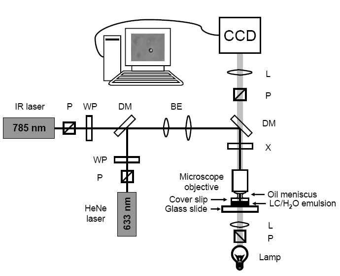
For performing the optical rotation experiments, a small volume of emulsion was placed on a microscope glass slide and covered with a thin (thickness of about 0.18 mm) glass coverslip, thus forming a thin cell (open on the sides). A 100 oil-immersion microscope objective (Carl Zeiss, NA=1.25) was used both to image the droplets on a CCD camera (using lamp illumination from below the cell, in combination with other optics) and to focus the input laser beams that were used to trap the droplets and induce their rotation, as discussed in the following (see Fig. 1). The objective was attached, via an oil thin film, to the glass coverslip. When needed, the microscopic imaging could be made in the crossed or nearly-crossed polarizers geometry, in order to visualize the droplet birefringence. CCD images and movies (acquisition rate of 50 frame/s) could also be recorded on a PC, for subsequent frame-by-frame analysis.
The setup for the optical trapping and manipulation is a dual-wavelength optical-tweezers apparatus (see Fig. 1). Our setup differs from usual optical tweezers arrangement in that two laser beams, respectively generated by a diode-pumped solid state laser (785 nm, subsequently called “IR” beam) and a He-Ne laser (=633 nm), are brought to a common focus at the specimen plane of the microscope objective. Both beams were able to achieve trapping of droplets for diameters in the 2-12 m range, as proved by a sudden stop (or confinement) of the droplet Brownian motion after trapping. The beam-waist (Airy disk) radius at focus is estimated to be about 0.4 m, in the adopted objective-overfilling configuration. Actually, due to the thickness of the glass coverslip, our optical trap center (roughly corresponding to the laser beam waist) could not be located right in the middle of the cell but was close to the coverslip. This fact might have led to some contacting of the droplets with the glass, particularly in the case of the largest droplets. In such cases the droplets may have experienced a somewhat stronger friction, and therefore our results on the rotational speed could be biased. However, any systematic effect will be identical for pure and dye-doped droplets and obviously independent of the light wavelength used for inducing the rotation. So, our comparison will remain valid. Moreover, the agreement between theory and experiments will show that these possible systematic effects are certainly small, at least for not too large droplets.
The common focus of the two lasers allowed us to switch the controlling beam from one wavelength to the other (e.g., to switch the He-Ne beam on and the IR off, or vice versa) without changing the trapped liquid crystal droplet. Since the He-Ne wavelength is close to the maximum of the dye absorption band, while the IR wavelength falls completely outside the absorption band, this corresponds to adding or removing the photoinduced effects, so as to allow for a direct comparison of the behavior obtained in the two cases with the same droplet.
Besides for trapping, the two beams were also used to induce the electromagnetic and photoinduced torques acting on the droplet and driving its reorientation or continuous rotation. By inserting along the beam (just before the microscope objective) a suitable birefringent wave plate, we could control the polarization of each beam (separately). In particular, we have used linear polarizations with an adjustable polarization plane and elliptical polarizations with an adjustable degree of ellipticity . We could also obtain certain specific polarization combinations of both beams together, such as one linear and the other circular or elliptical. By using a suitably dispersive optically-active plate (home-built using a chiral-doped randomly oriented liquid crystal cell) we could also obtain two linearly polarized beams with two different polarization planes, forming an angle of .
Micron-sized LC droplets are known to show either one of two possible director spatial distribution Erdmann et al. (1990); Kralj and Žumer (1992); Juodkazis et al. (2003): axial (or bipolar), already discussed in the previous section, and radial, which has full spherical symmetry and a hedgehog defect at the droplet center. The images of axial and radial droplets under a polarizing microscope can be almost identical. However, we could identify axial droplets by checking that their image changed if the microscope polarizers were rotated, or by looking directly at their dynamical behavior under the laser beam, as only axial droplets could be readily set in rotation if illuminated with circular polarizations or reoriented using linear polarizations. Radial droplets could not be rotated at all (because all the optical torques vanish, due to radial symmetry, if absorption is neglected). About 80-90% of the droplets of our emulsions were found to be axial footnote4 . In the following we will only refer to them.
Using linearly polarized light, we could easily fix the average director orientation of our trapped axial droplets. By looking at the microscopic image pattern under crossed polarizers Juodkazis et al. (1999b); Sandomirski et al. (2004), we verified that the director orientation was indeed parallel to the polarization plane. By slowly rotating the polarization by means of a half-wave plate, the droplet alignment followed the polarization. These experiments could be done both with pure liquid crystal droplets and with dye-doped ones, the latter both with IR and He-Ne beams, without much difference.
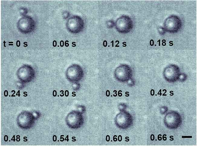
Using elliptically polarized beams and axial droplets, we could perform the analogue of the classic Beth’s experiment Beth (1936), i.e., set the trapped droplets in continuous rotation by the transfer of angular momentum with light. Depending on the droplet size and on the laser beam power and ellipticity, the rotation could range from very slow (periods of several seconds) to very fast (down to the millisecond range). We used two different methods for measuring the spinning of droplets by analyzing the frames of a droplet rotation movie. First, using the crossed-polarizers geometry we could image the birefringence rotation, corresponding to the director motion, as a periodic pattern modulation in time. For the smallest droplets, we could observe a significant modulation of light intensity during the rotation even without the analyzer, presumably due to the anisotropic scattering cross-section of the droplets. Second, we could also measure the droplet fluid rotation (i.e., regardless of director rotation) when a smaller satellite droplet (or another small object) happened to get trapped close to the rotating droplet and was thereby dragged around, as in the case shown in Fig. 2. The rotation speed measured in these two ways (when the satellite was sufficiently small and close to the rotating droplet) were always found to be the same.
In order to check if the photoinduced effects give rise to a rotation speed enhancement, on each droplet we measured the rotation frequency induced by the He-Ne and the IR beams as a function of input beam polarization ellipticity. We repeated this for many different droplets having a range of diameters. We also measured the rotation frequencies induced in pure (undoped) liquid crystal droplets, although of course in this case the comparison could not be done with exactly the same droplet sizes. In all these measurements, the two laser beams were adjusted for having a roughly equal angular momentum flux, as given by Eq. (20). In particular, the light power measured after the microscope objective was about 4.1 mW for the He-Ne beam and 2.8 mW for the IR in most data shown. These values correspond, for a given polarization ellipticity , to the same angular momentum flux to within 15% ( Nm for the case of circular polarization). However we also investigated the power dependence of the rotation frequency in some droplets.
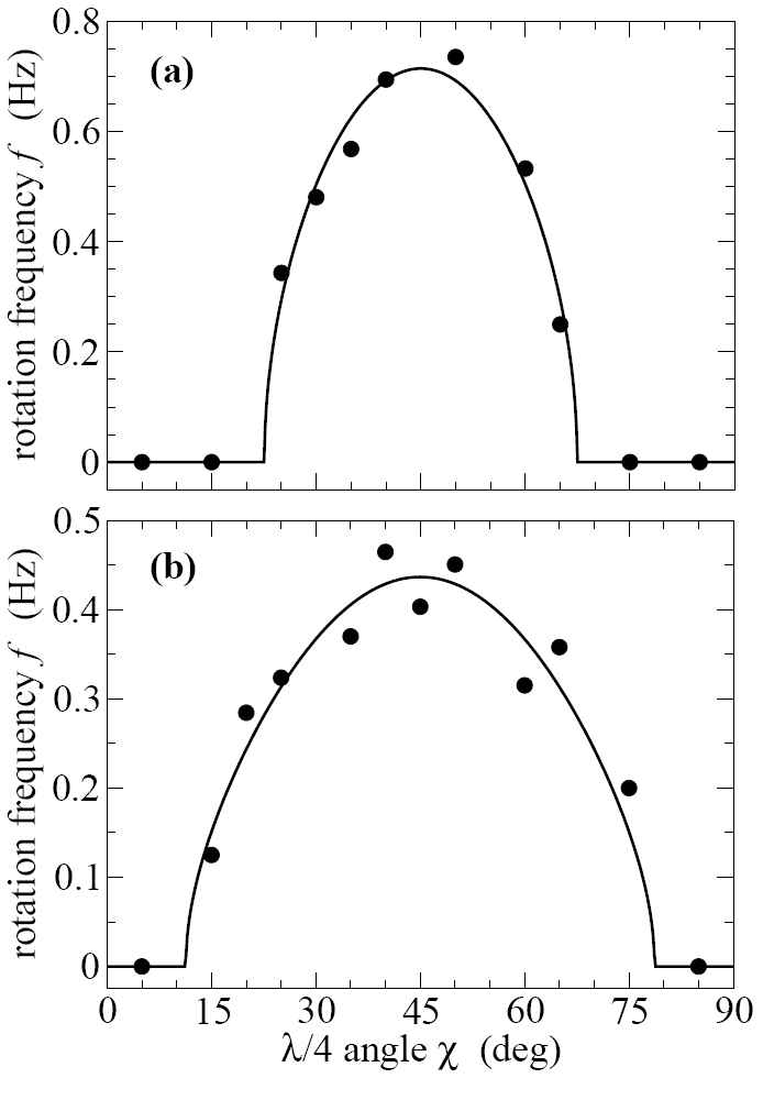
An example of the measured rotational frequencies of a given droplet versus light polarization ellipticity (given by the angle ) is shown in Fig. 3. We actually measured this dependence for many other droplets of different sizes, made of both pure and dye-doped LC. Each of these measurements was then fitted by means of Eq. (26). In these fits the radius was fixed at the value determined by analyzing the droplet microscopic picture. The absorbance at 633 nm was instead measured separately on a bulk sample (we obtained cm-1) and then kept fixed to this value in all fits. The constants and were adjusted for best fit. was found to be roughly consistent (to within a factor two in most cases) with its predicted value, as given by Eq. (27) (using the known or measured values of the laser power and frequency, water viscosity and droplet radius). From the best-fit value of , we could also estimate the birefringence , which was almost always found to fall in the range 0.11-0.13 (average 0.12), with a few droplets giving a value of 0.10 and 0.14. These values are inconsistent with the known refractive index difference of the bulk material ( at 589 nm, Merck data sheet). We ascribe this discrepancy to the strong approximations associated with the PSA model (in particular to neglecting the contribution of obliquely propagating waves in the focused beam), as a strong depression of the optical anisotropy due to confinement effects is not plausible for micrometric droplets. It is apparent from Fig. 3 that the rotational behavior of a dye-doped LC droplet under IR or He-Ne laser beams is not identical. However, the difference is well explained by the different wavelength and absorbance in Eq. (26), while no particular rotation enhancement is seen in the He-Ne case, where photoinduced dye effects should take place.
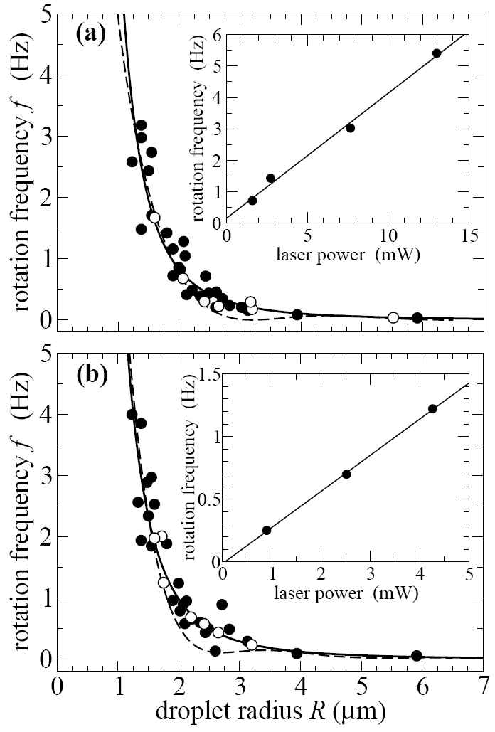
In Fig. 4 we show the rotation frequency observed for several pure LC (open symbols) and dye-doped LC (filled symbols) droplets of different sizes using circularly polarized light. Panels (a) and (b) refer to rotations induced by the IR and He-Ne beam, respectively. The insets show the corresponding (linear) dependence on laser power for a fixed droplet (incidentally, this linear behavior supports our assumption that the laser light induces no significant distortion of the director configuration in the droplet, in the power range used in our experiments).
Again, a first conclusion that can be immediately drawn from this figure is that no significant rotation speed enhancement takes place in the dye-doped LC case with the He-Ne beam as compared both to the IR beam case and to the pure LC case. Should the photoinduced torque be external, one would have expected a rotation speed enhancement by a factor of the order of , i.e., of several hundreds.
In Fig. 4, the dashed lines are the predictions of Eq. (26) after adjusting the laser power for best-fit to data. The birefringence was kept fixed to the average value obtained from the measurements discussed above (and confirmed by the threshold ellipticity data, as discussed below), but increasing its value led to worse fits (in particular, leads to very bad fits). From Fig. 4, it is seen that the agreement between data and theory is reasonable, although there is a statistically significant discrepancy. In particular, the data do not show at all the oscillations predicted by Eq. (26) (of course, small residual oscillations might be hidden in the noise). Moreover, for both lasers the best-fit values of the power were found to be about a factor two smaller than the actual measured values (assuming a water viscosity cP, corresponding to the room temperature of 20∘C). The solid lines in Fig. 4 correspond instead to the simpler theory , as given by Eq. (27), obtained in the limit . In this case, no adjustable parameter was used, i.e., the values of the laser power and of the water viscosity are both fixed to the known values ( cP). Nevertheless, it is seen that the agreement is even better and that the same theory (taking into account the difference in light power and frequency) explains all the data, i.e., both the dye-doped case with He-Ne beam, when there is significant absorption, and the IR beam or pure LC cases, when there is no absorption (incidentally, this agreement shows that any systematic effect due to the droplet closeness to the glass wall is essentially negligible, except perhaps for the largest droplets). This better agreement of the simplified theory obtained for clearly cannot be truly ascribed to absorption (negligible in the IR and pure droplets case). It is instead the likely result of light diffraction, oblique propagation and other effects neglected in the simple PSA calculation, which may all contribute to averaging out the oscillations due to the outgoing light, as discussed previously. This view is also confirmed by the fact that previous works on transparent liquid crystal droplets reported similar observations Juodkazis et al. (1999a); Juodkazis et al. (2003).
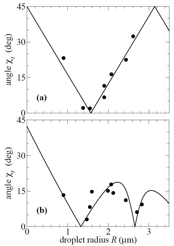
Let us now consider the behavior of the threshold ellipticity for droplet rotation versus the droplet radius . For each droplet and wavelength, was obtained from the best fits performed on the measured rotation frequency versus light ellipticity (such as that shown in Fig. 3). In particular, is entirely determined by the best-fit value of , via Eq. (19). The resulting data are shown in Fig. 5, together with the predictions obtained using Eq. (19) combined with and adjusting the birefringence for best fit. It is seen that the theory agrees reasonably well with the experiment. The best fit is for for both laser wavelengths, confirming the average value obtained before. Moreover, for the He-Ne case the effect of light absorption is clearly seen in the data.
It must be noted that Eq. (19) is based on the PSA model including the effect of the light emerging from the droplet. Indeed, taking the limit leads to for all droplet sizes, which is inconsistent with our data. We do not know exactly why the PSA-neglected effects do not affect the threshold ellipticity as much as the rotation frequency (apart from the depression of ), but this is what we actually find and what was also reported in previous works Juodkazis et al. (1999a); Juodkazis et al. (2003). At any rate, we stress that all inaccuracies of PSA theory do not affect our comparison between pure and dye-doped droplets or between IR and He-Ne beams.
Finally, we tried to find evidences of a decoupling between the droplet fluid and the average director degrees of freedom. In particular, we searched for the effects predicted by the UDA model to occur when the He-Ne and IR beams are simultaneously impinging on the droplet, both linearly polarized with the two polarization planes forming an angle of about 40∘. In order to visualize the droplet fluid rotation independently of the director, we imaged the dynamics of droplets having small satellites (such as smaller droplets or other particles in the suspension), so that the droplet surface flow would be highlighted by the revolution of these dragged objects. However, despite many efforts, we could not find any sign of a steady-state decoupling between the director and the fluid motion in the droplets (except, perhaps, for some complex transient effects) and, therefore, of a corresponding continuous fluid rotation of the droplet. This probably indicates that elastic effects associated with the nonuniform director distribution and a not perfectly spherical shape of the droplet (effects neglected in the UDA model), concur to keeping the orientational and flow degrees of freedom locked to each other.
V Conclusions
In summary, we have studied for the first time the dynamical behavior of droplets of dye-doped nematic liquid crystal trapped in water by a strongly focussed laser beam and set in rotation by the optical torques generated by the same beam. We searched for evidences of a dye-induced enhancement of the droplet rotation speed associated with photoinduced effects, but no enhancement was found. This null result is in accordance with the leading first-order theory of these photoinduced effects Jánossy (1994); Marrucci and Paparo (1997) and directly proves that the dye-enhanced optical torque is not associated with an exchange of angular momentum with light or other external degrees of freedom, but that it must instead be associated with a fully internal exchange of angular momentum between the molecular orientation and fluid flow degrees of freedom. The latter exchange is correctly described only by assuming the existence of a dye-induced stress tensor acting on the fluid flow in the illuminated region, as first proposed in Ref. Marrucci and Paparo (1997). This photoinduced stress tensor embodies the internal “reaction” to the photoinduced torque acting on the molecular director. Our null result is therefore also a direct proof of the actual existence of this stress tensor.
The interplay between fluid flow and director dynamics within the droplet is also predicted by our models to give rise to very peculiar effects, such as a continuous droplet fluid rotation induced by two linearly polarized optical waves having different polarization planes. However, the occurrence of these phenomena requires to unlock the constraint existing between the droplet fluid and the molecular director. This constraint is partly due to viscous forces, but it may also be due to elastic interactions combined with anchoring forces. Experimentally, we could not reach a situation in which this constraint was effectively broken, so we could not demonstrate the predicted effect.
Acknowledgements.
We thank R. Eidenschink of Nematel for providing HK271. This work was supported by the Fondo per gli Investimenti della Ricerca di Base (FIRB) of the Italian Ministero dell’Istuzione, dell’Università e della Ricerca. I. J. acknowledges the support from the Hungarian Research Grants OTKA T-037275 and NKFP-128/6. *Appendix A Proof of the electromagnetic torque identity
To prove the validity of identity (30), we start from Eq. (14) as applied to the case , which can be rewritten as follows:
| (36) |
We must therefore prove that the integral vanishes identically within the SDA and UDA approximations.
Let us consider the first term in Eq. (8) of the electromagnetic stress tensor. This is an isotropic pressure-like term, i.e., of the form . For such a term, the integral (36) can be recast into a surface integral as shown in the following:
Within the SDA, the surface element normal and the position vector will be parallel to each other, and therefore their cross product (as expressed by their product times the antisymmetric Levi-Civita tensor) vanishes identically.
Let us now consider the second term in Eq. (8) of the stress tensor. Omitting the time-average for brevity, we must consider the following integral
where we have used the two Maxwell equations and and introduced the dielectric tensor to express in terms of . The dielectric tensor is always symmetric for a permutation of its indices. Moreover, within UDA and constant density approximations, the dielectric tensor is also uniform within the droplet. Exploiting these two properties, we obtain
where the first integral vanishes identically (within SDA) as it has taken a pressure-like form.
The third stress-tensor term, in the magnetic field, can be treated analogously to the second, obtaining the following expression:
Summing up the three contributions, the whole integral is reduced to the following:
| (37) | |||||
This expression (which is a part of the electromagnetic torque due the so-called Abraham force Landau and Lifschitz (1984), which is completed if one considers also the effect of the neglected electromagnetic force mentioned in footnote2 ) corresponds to a true residual electromagnetic torque which does not vanish in general. However, after optical-cycle averaging, its order of magnitude can be estimated as follows:
| (38) |
where is a characteristic time of the droplet dynamics and is the droplet crossing time of light. In our case , making this contribution totally negligible with respect to and therefore the identity (30) valid to high accuracy.
References
- (1) For a recent review see, e.g., L. Marrucci and Y. R. Shen in The Optics of Thermotropic Liquid Crystals, ed. by R. Sambles and S. Elston, Taylor & Francis, London, 1998. For more recent developments on the same topic, see B. Piccirillo and E. Santamato, Phys. Rev. E, 69, 056613 (2004); E. Brasselet et al., J. Opt. Soc. Am. B 22, 1671 (2005); and D. O. Krimer et al., J. Opt. Soc. Am. B 22, 1681 (2005).
- Jánossy et al. (1990) I. Jánossy, A. D. Lloyd, and B. S. Wherrett, Mol. Cryst. Liq. Cryst. 179, 1 (1990).
- Jánossy and Kósa (1992) I. Jánossy and T. Kósa, Opt. Lett. 17, 1183 (1992).
- Jánossy (1994) I. Jánossy, Phys. Rev. E 49, 2957 (1994).
- Marrucci and Paparo (1997) L. Marrucci and D. Paparo, Phys. Rev. E 56, 1765 (1997).
- Marrucci et al. (1997) L. Marrucci, D. Paparo, P. Maddalena, E. Massera, E. Prudnikova, and E. Santamato, J. Chem. Phys. 107, 9783 (1997).
- Marrucci et al. (2000) L. Marrucci, D. Paparo, M. R. Vetrano, M. Colicchio, E. Santamato, and G. Viscardi, J. Chem. Phys. 113, 10361 (2000).
- Kreuzer et al. (2002) M. Kreuzer, F. Hanisch, R. Eidenschink, D. Paparo, and L. Marrucci, Phys. Rev. Lett. 88, 013902 (2002).
- Kreuzer et al. (2003) M. Kreuzer, E. Benkler, D. Paparo, G. Casillo, and L. Marrucci, Phys. Rev. E 68, 011701 (2003).
- Truong et al. (2005) T. V. Truong, L. Xu, and Y. R. Shen, Phys. Rev. E 72, 051709 (2005).
- Palffy-Muhoray and E (1998) P. Palffy-Muhoray and Weinan E, Mol. Cryst. Liq. Cryst. 320, 193 (1998).
- (12) More generally one must use the local order-parameter traceless tensor . This can be particularly important in the smallest droplets, where significant order parameter depressions can be induced by the strong director gradients.
- Landau and Lifschitz (1984) L. Landau and E. Lifschitz, Electrodynamics of Continuous Media (Pergamon Press, Oxford, 1984).
- de Gennes and Prost (1993) P. G. de Gennes and J. Prost, The Physics of Liquid Crystals, 2nd ed. (Oxford University Press, Oxford, 1993).
- Chandrasekhar (1992) S. Chandrasekhar, Liquid Crystals, 2nd ed. (Cambridge University Press, Cambridge, 1992).
- (16) The divergence of the stress tensor actually does not provide the complete electromagnetic force in electro-dynamical systems. An additional force of the form , where is the Poynting vector of the optical wave, should be included (this is part of the so-called Abraham force), as discussed in Ref. Landau and Lifschitz (1984). However, after optical-cycle averaging this last term is negligible whenever the matter dynamics is very slow with respect to the droplet crossing time by light, as in our case (see the Appendix for a fuller explanation).
- Finkelmann et al. (2001) H. Finkelmann, E. Nishikawa, G. G. Pereira, and M. Warner, Phys. Rev. Lett. 87, 015501 (2001).
- Yu et al. (2003) Y. Yu, M. Nakano, and T. Ikeda, Nature 425, 145 (2003).
- (19) In equation (13), a contribution to the angular momentum density associated with the electromagnetic field itself, of the form , has been neglected for the same reasons as those discussed in footnote2 .
- Erdmann et al. (1990) J. H. Erdmann, S. Žumer, and J. W. Doane, Phys. Rev. Lett. 64, 1907 (1990).
- Kralj and Žumer (1992) S. Kralj and S. Žumer, Phys. Rev. A 45, 2461 (1992).
- Friese et al. (1998) M. E. J. Friese, T. A. Nieminen, N. R. Heckenberg, and H. Rubinsztein-Dunlop, Nature 394, 348 (1998).
- Juodkazis et al. (1999a) S. Juodkazis, M. Shikata, T. Takahashi, S. Matsuo, and H. Misawa, Jpn. J. Appl. Phys. 38, L518 (1999a).
- Juodkazis et al. (2003) S. Juodkazis, S. Matsuo, N. Murazawa, I. Hasegawa, and H. Misawa, Appl. Phys. Lett. 82, 4657 (2003).
- Humblet (1943) J. Humblet, Physica 10, 585 (1943).
- Jánossy and Lloyd (1991) I. Jánossy and A. D. Lloyd, Mol. Cryst. Liq. Cryst. 203, 77 (1991).
- Jákli et al. (1991) A. Jákli, D. R. Kim, M. R. Kuzma, and A. Saupe, Mol. Cryst. Liq. Cryst. 198, 331 (1991).
- (28) When doing experiments with 5CB droplets, it was relatively easy to heat them above the clearing temperature (nematic to isotropic transition), either by laser-induced heating of the single droplet or by heating the whole sample. In any case, radial droplets usually transformed into axial after being heated above the clearing point and then left relaxing back to the nematic phase. This showed that axial alignment is probably the most stable one.
- Juodkazis et al. (1999b) S. Juodkazis, M. Shikata, T. Takahashi, S. Matsuo, and H. Misawa, Appl. Phys. Lett. 74, 3627 (1999b).
- Sandomirski et al. (2004) K. Sandomirski, S. Martin, G. Maret, H. Stark, and T. Gisler, J. Phys. Cond. Matt 16, S4137 (2004).
- Beth (1936) R. A. Beth, Phys. Rev. 50, 115 (1936).