Voltage rectification effects in mesoscopic superconducting triangles: experiment and modelling
Abstract
The interaction of externally applied currents with persistent currents induced by magnetic field in a mesoscopic triangle is investigated. As a consequence of the superposition of these currents, clear voltage rectification effects are observed. We demonstrate that the amplitude of the rectified signal strongly depends on the configurations of the current leads with the lowest signal obtained when the contacts are aligned along a median of the triangle. When the contacts are aligned off-centered compared to the geometrical center, the voltage response shows oscillations as a function of the applied field, whose sign can be controlled by shifting the contacts. These results are in full agreement with theoretical predictions for an analogous system consisting of a closed loop with a finite number of identical Josephson junctions.
pacs:
74.25.Fy,74.25.Sv,74.78.Na,73.40.Ei, 74.81.Fa, 85.25.CpA considerable attention has been attracted in the last years to the mechanisms responsible for the ratchet effects in a broad variety of physical systems such as colloidsLibál et al. (2006), granular materialsFarkaz et al. (1999), fluidsMatthias and Muller (2003), atoms in optical trapsGommers et al. (2006), electrons in semiconductor heterostructuresLinke et al. (2003) and Josephson systemsZapata et al. (1996); Falo et al. (1999); Shalóm and Pastoriza (2005). In all cases a net flux of particles driven by a zero average alternating excitation results from the interaction of the media with an asymmetric potential. This behavior has been also theoretically predicted and experimentally corroborated for the motion of quantum flux lines in superconducting samples with a pinning landscape lacking inversion symmetry Lu et al. (2007); Cole et al. (2006); de Souza Silva et al. (2006); Van de Vondel et al. (2005); Wambaugh et al. (1999); Villegas et al. (2003); Silhanek et al. (2007). In superconducting systems, this effect manifests itself as a non-zero dc voltage even when an ac excition is sent through the superconductor, thus acting as a voltage rectified. Interestingly it has been recently demonstrated that the presence of this voltage rectification in a superconductor do not necessarily imply the motion of vortices in an asymmetric pinning potential but might also result from non symmetric current distributions in the superconducting sample de Vondel et al. (2007).
Indeed, first Dubonos et.al.Dubonos et al. (2003) reported rectification effects in asymmetric superconducting rings. Later on, Morelle et. al.Morelle et al. (2006) showed that similar effects are observed in singly connected structures if the current injection is off-centered. In both cases the effect was attributed to an asymmetry in compensation or reinforcement of an external bias current by the field induced persistent currents, causing a difference in critical current for a positive or negative applied external current. More recently Van de Vondel et.al. de Vondel et al. (2007) showed that both kinds of rectification, due to ratchet vortex motion and due to current compensation effects can coexist in superconducting samples with periodic arrays of triangular antidots.
In this work we investigate the influence of the position of the current/voltage probes on the resultant rectification effect in microsized superconducting triangles. We show that an ac current injected above the geometrical center of the triangle gives an opposite rectification signal than for current injection below the geometrical center of the triangle. In addition we show that a lower signal is obtained if the contacts are attached along a median of the triangle, so that upper and lower part of the triangle are symmetric around this line. This result demonstrates that the superposition of a field induced persistent current with the bias current qualitatively accounts for the observed phenomena. To interpret these data, we also used a theoretical model system consisting of a closed loop of Josephson junctions containing the necessary ingredients (persistent and bias currents) to reproduce the experimental findings.
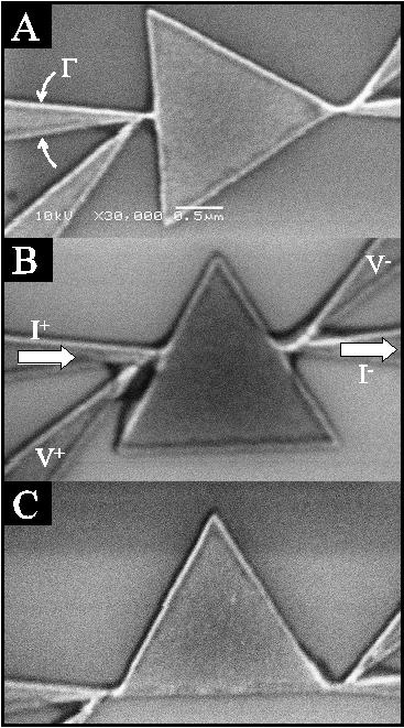
The superconducting triangles are made of a 50-nm-thick Al film thermally evaporated on Si/SiO2. The structures are obtained by deposition through an e-beam patterned resist mask followed by a lift-off procedure. All samples consist of an equilateral triangle with an area of m2 and four wedge-shaped current/voltage contacts. The typical superconducting coherence length estimated from unpatterned films is about (0) nm. Three different contacts configurations are investigated: current injected along a median (see the scanning electron microscopy (SEM) image in Fig. 1(a)), current injected above the geometrical center (Fig. 1(b)), and current injected at the base of the triangle (Fig. 1(c)). From hereon we refer to these samples as sample A, sample B, and sample C, respectively.
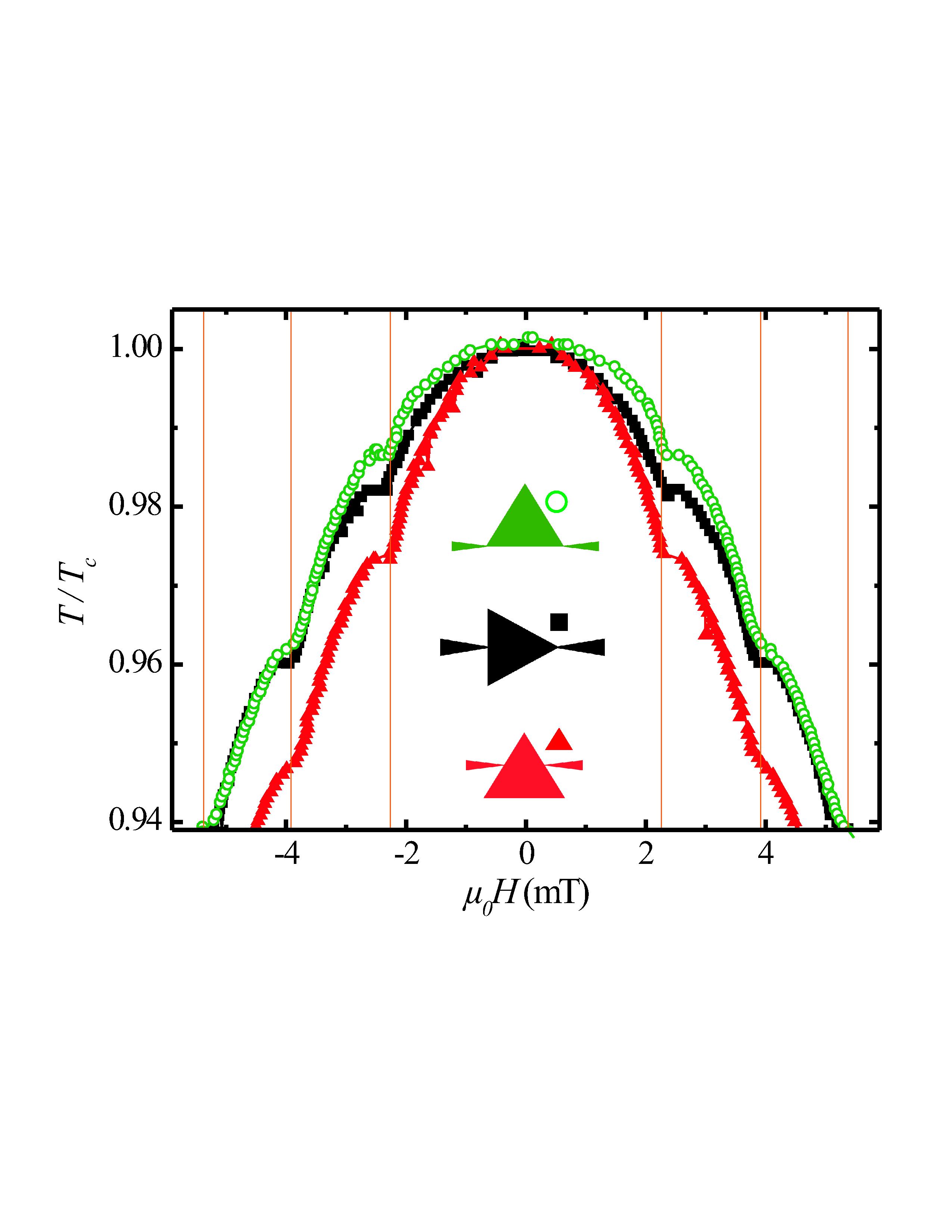
The phase boundary for each of the studied samples is summarized in Fig. 2 using an ac drive of 0.1 peak-to-peak. Here is estimated by a resistance criterion of 10 percent of the normal state value. The obtained critical temperatures for samples A, B and C are 1.365 K, 1.355 K and 1.34 K, respectively. All phase boundaries exhibit clear Little-Parks oscillations with local minima at fields where the vorticity switches from to Tinkham (1975). The vertical lines in Fig. 2 show theoretical estimates of the geometry-dependent transition fields for a triangular sample of area m2Chibotaru et al. (2001). This value is in a good agreement (within 7%) with the area estimated from the SEM images shown in Fig. 1. The most obvious feature in Fig. 2 is the different field dependence of for the three studied samples with the higher for sample C and lower for sample B. Since the only difference between samples is the position of the contact leads, the observed discrepancy in can be unambiguously attributed to the influence of these contacts on the nucleation of the superconducting condensate. It is a well established factFomin et al. (1997); Morelle et al. (2002); Schweigert and Peeters (1999) that surface superconductivity is greatly enhanced in wedge-shaped structures. Since the contact leads have a narrower apex angle (15∘) than the triangle (60∘), superconductivity starts to appear at these points first. Under these circumstances the transition to the superconducting state is expected to occur at higher temperatures in sample C where both wedges, the contacts and the vertices of the triangle, reinforce the surface nucleation effect. Similar effects were anticipated by de Gennes and Alexander for small superconductor with leads attached to itde Gennes (1981); Alexander (1983).
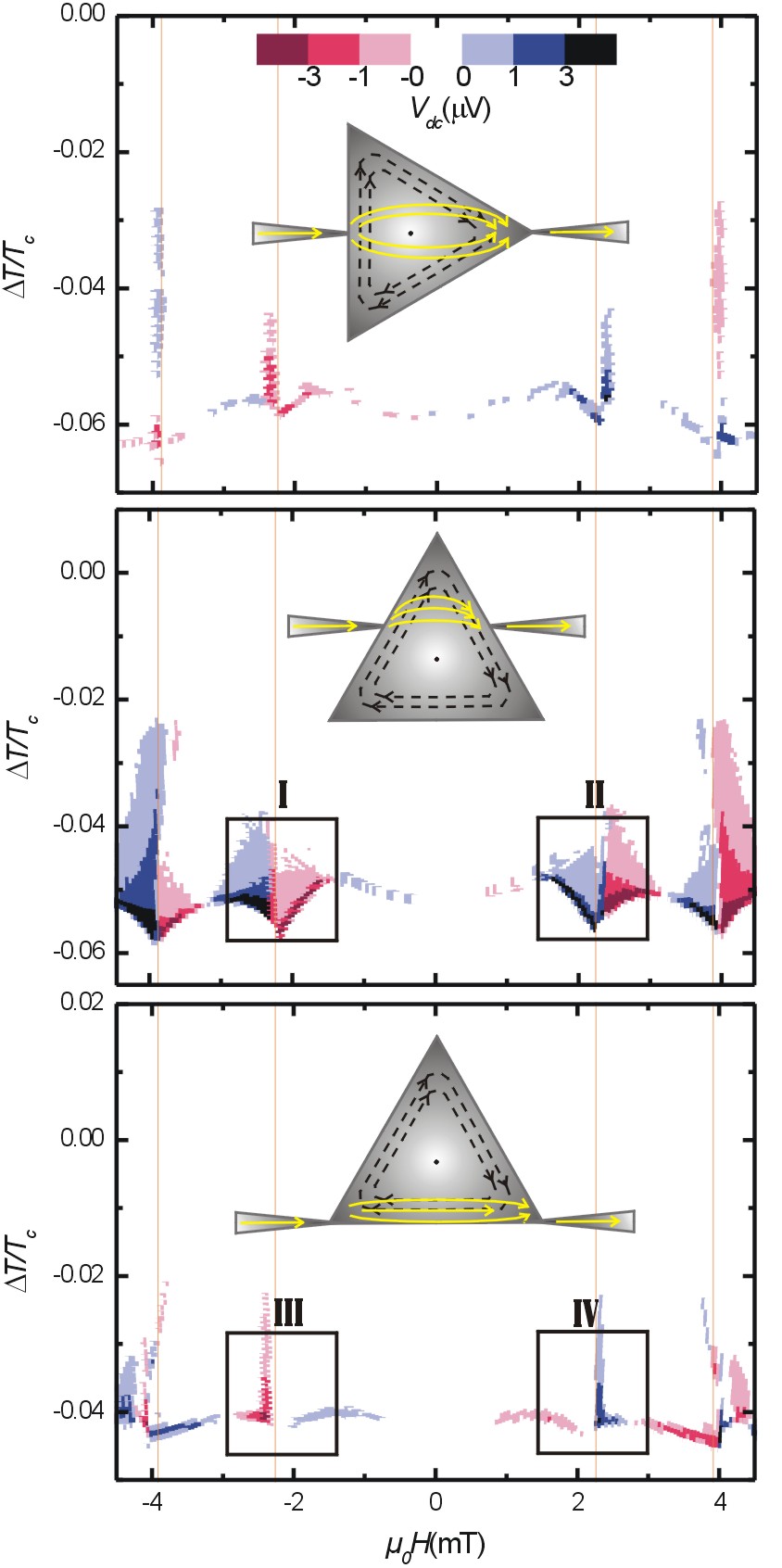
Let us now focus on the interaction of the externally applied currents with the persistent circular currents induced by the magnetic field. In order to resolve better the difference between positive and negative bias current we apply an ac drive with amplitude of 10 A peak-to-peak and frequency 3837 Hz while measuring the average dc voltage. In this way, when the samples are in the normal state () or in absence of screening currents (), the dc output voltage should be zero, as indeed observed. In contrast to that, if screening currents are present, as a result of an applied non zero homogeneous field, then the superposition of the applied current with the circulating persistent currents in the triangle gives a different contribution when they reinforce than when they counteract each other. In other words, a net dc voltage signal is recorded. Fig. 3 shows the measured dc voltage as a function of the applied magnetic field and temperature T for the samples A, B, and C. The data are here presented with a parabolic background subtracted, so T = (H)-( - b H2), with b a constant different for each sample. In order to make a reliable comparison of the measured signal between different samples we have normalized by the distance between the voltage contacts.
Sample B has the same contact configuration as the one earlier reported in refMorelle et al. (2006), with the leads placed above the geometrical center of the triangle. As expected, this sample reproduces the previous results, namely an abrupt change of sign in the dc response (see the color changes in frames I and II in Fig. 3) every time the vorticity of the system changes from to , which is associated with the reversal of the persistent currents, and a smooth crossover in between two consecutive fields associated with the progressive reduction and later inversion of the screening currents. The origin of the rectified voltage is related to the unbalanced distribution of the external applied current and their compensation with the persistent currents circulating around the geometrical center. Since the current leads are located above the geometrical center, the applied current mainly flows trough the upper part of the triangle, causing an asymmetry by compensating (or reinforcing) the screening currents more in the upper part then in the lower part. A schematic drawing of the circulating persistent current and the applied current are shown as an inset in each graph of Fig. 3.
Notice that besides the above mentioned voltage sign reversals related to Little-Parks oscillations, an unexpected sign reversal is observed in the Meissner phase for sample B (middle panel in Fig. 3). The fact that this effect, unlike the Little-Parks oscillations, is much weaker and not systematically observed for all measured samples indicates that it is sample dependent and cannot be related to the circulating screening currents.
According to the above described scenario, if the line along which the current is inserted is not shifted compared to the center of the circulating persistent currents, as in sample A, no rectification effects should be observed. Since the upper part of the triangle is in this case a mirror image of the lower part, the current is distributed equally around the center of the triangle, and no asymmetry in compensation ( or reinforcement) is expected. This is consistent with the strongly reduced signal detected in sample A (about three times weaker in amplitude and located in a smaller temperature-field area), in comparison with sample B. The origin of this small signal likely lies in the inevitable minor asymmetries produced by shadow effects during the material deposition.
The most compelling evidence that indeed the observed rectification effects originate from the direct superposition of the external current and the field induced persistent circular currents comes from the measurements shown in the lower panel of Fig. 3 corresponding to sample C. In sample C, unlike sample B, the current injection is well below the geometrical center of the triangle and therefore the situation should be reversed in comparison to sample B. In other words, for the fields where a positive signal is recorded in sample B (indicating that the positive current is reinforced in the top of the triangle) an opposite sign is expected for sample C (i.e. the positive current is compensated at the base of the triangle). This reversal between samples B and C is clearly visible for vorticity by comparing the indicated sections I, II with III, IV in Fig. 3.
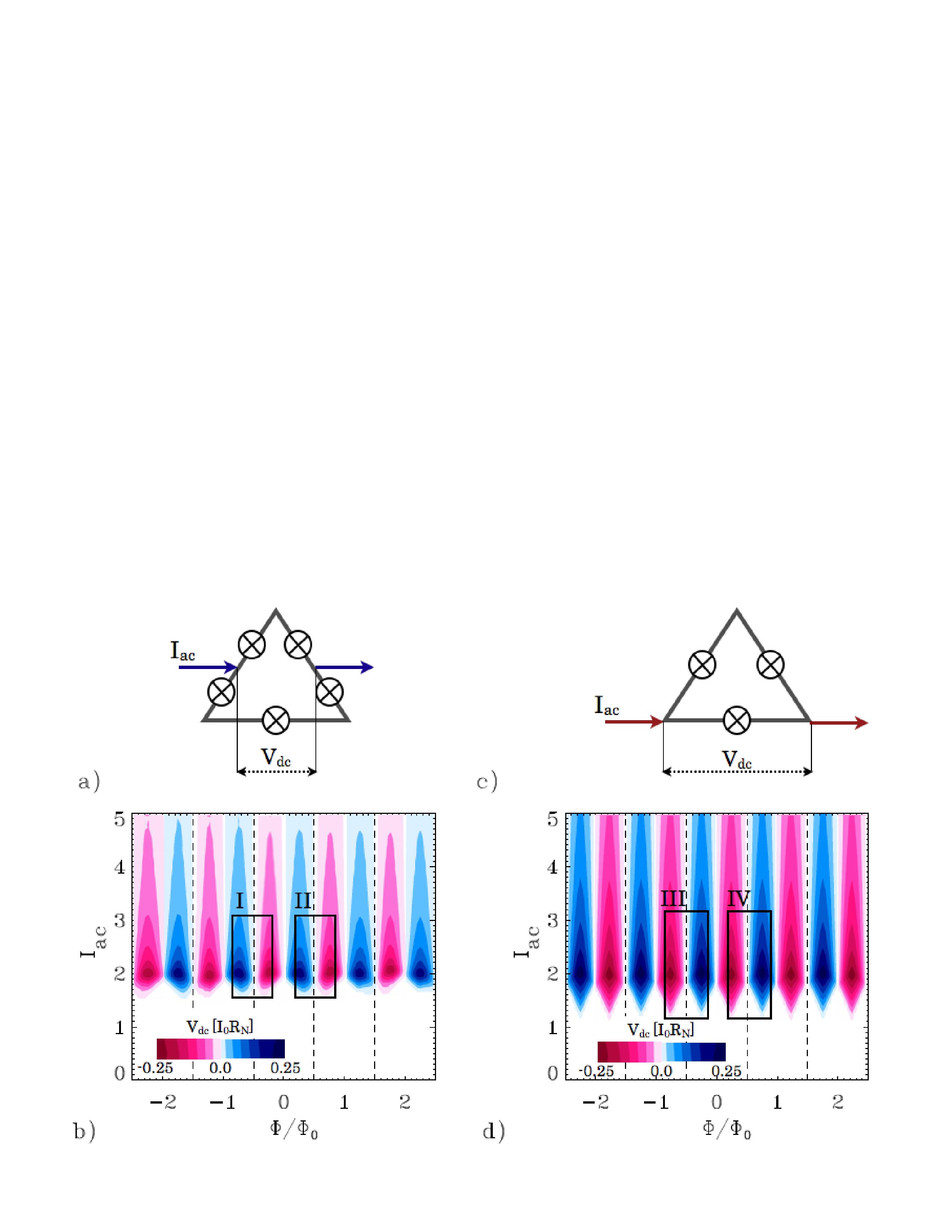
As we already briefly mentioned above, the necessary ingredients to observe the sort of voltage rectification described here are (i) field induced persistent currents and (ii) off-center injection of external currents. This recipe suggests that similar rectification effects should be also present in every system with a persistent current and an asymmetric current path, thus resulting in a difference in critical current for a positive or negative applied current. An example of such a system fulfilling these conditions consists of a closed loop with a number of identical Josephson junctions (JJ). A complementary model with and unequal JJ has been analyzed recently by BergerBerger (2004). Without losing generality the main effects can be seen in two simple configurations: a ring with three junctions and one with five junctions, as schematically depicted in Fig. 4.
The main assumptions for the calculations are that the superconducting order parameter is such that with the same constant on all islands, is spatially constant in each island, and that the weak links between them can be modeled as identical SNS junctions. It is also assumed that the total magnetic field is spatially and temporally constant. The Hamiltonian of a ring with weak linked SNS-junctions is the following:
| (1) |
where is the Josephson energy, is the phase
difference at the junction , and is the phase of
the superconducting island centered at
with the ring
radius.
The magnetic field contribution to the phase difference is
the line integral of the vector potential between sites and
,
| (2) |
Taking and the gauge for the vector potential , and introducing the flux number through the ring we have,
| (3) |
We consider the resistive shunted model using a resistive channel for the normal electron current in parallel with a Josephson current channel, satisfying Kirchhoff laws for the current conservation in each node. We inject a current between junctions and , and extract it junctions away, between junctions and . The resulting set of dimensionless equations for the currents flowing in the ring is the following:
| (4) |
| (5) |
| (6) |
which are first order differential equations for the time evolution of the phase variables . Let us note that each junction interacts with all the others through , the total current in the upper branch of the circuit, which represents a kind of mean-field interaction plus a drive. The equations can be easily solved numerically by using the Runge-Kutta method in order to compute the instantaneous voltage drop between source and drain, which can be expressed as,
| (7) |
Using this model, the rectified mean dc voltage is calculated as function of the magnetic field for an ac-sinusoidal current with different amplitudes in the low frequency limit. We normalize currents by the single junction critical current and voltages by , with the resistence of the resistive channel. The results for and , both with the same source-drain distance , are shown in Fig. 4. We can clearly see that both, the and the devices, can rectify, , if with an integer, and if is above a critical threshold which is smaller for . We can also observe that the maximum of is almost the same in both cases, although for fixed , decays slower as a function of for . More importantly, although qualitatively, the same oscillations are observed as in the experiment as a function of vorticity.
The experimental results are measured as a function of temperature with a constant applied current, while in the model the applied current is changed, keeping the temperature constant. However, the effect is similar since both increasing T and have an analogous influence on the system driving it towards the resistive state.
In brief, the predicted rectification in this model system is similar to the effects measured in the Al triangle. It is worth noticing that from the point of view of the superconducting condensate our experimental system can be regarded as a multiply connected structure since the order parameter is maximum at the vertices and minimum at the sides of the triangle (see sketch in Fig. 4). Furthermore, for certain fields and temperatures at the middle of the sides of the triangle and the system can be actually thought of as a ring-like structure with SNS-junctions. This scenario is modified by the presence of contact leads which locally enhance the order parameter. In this case, sample B having the contacts at the sides can be directly compared with the five junctions ring whereas the ring imitates the response of sample C. Indeed, this association can be further justified by noting in frames I and III (or II and IV) of Fig. 4 that, for the same , the and Josephson circuits have opposite responses (for a fixed ), as it is also found experimentally by comparing in the same frames of Fig. 3 the response of samples B and C for the same .
In conclusion, we studied the influence of contacts on the rectification effect in superconducting triangles. We demonstrate that the sign of the rectification voltage depends on the position of the current contacts. These findings are in clear agreement with rectification effects obtained in the framework of the theoretical model presenting triangle as a micronet of identical Josephson junctions.
This work was supported by the K.U.Leuven Research Fund GOA/2004/02 program, the Belgian IAP, the Fund for Scientific Research – Flanders (F.W.O.–Vlaanderen), the F.W.O. fellowship (A.V.S.), and by the ESF ”Nanoscience and Engineering in Superconductivity (NES)” programs.
References
- Libál et al. (2006) A. Libál, C. Reichhardt, B. Jankó, and C. J. Olson Reichhardt, Phys. Rev. Lett. 96, 188301 (2006).
- Farkaz et al. (1999) Z. Farkas, P. Tegzes, A. Vukics, and T. Vicsek, Phys. Rev. E 60, 7022 (1999).
- Matthias and Muller (2003) S. Matthias and F. Muller, Nature 424, 53 (2003).
- Gommers et al. (2006) R. Gommers, S. Denisov, and F. Renzoni, Phys. Rev. Lett. 96, 240604 (2006).
- Linke et al. (2003) H. Linke, T. Humphrey, A. Lofgren, A. Sushkov, R. Newbury, R. Taylor, and P. Omling, Science 286, 2314 (2003).
- Zapata et al. (1996) I. Zapata, R. Bartussek, F. Sols and P. Hanggi, Phys. Rev. Lett.77, 2292 (1996).
- Falo et al. (1999) F. Falo, P. J. Martínez, J. J. Mazo and S. Cilla, Europhys. Lett. 45, 700 (1999); E. Trías, J. J. Mazo, F. Falo, and T. P. Orlando, Phys. Rev. E. 61, 2257 (2000).
- Shalóm and Pastoriza (2005) D. E. Shalóm and H. Pastoriza, Phys. Rev. Lett. 94, 177001 (2005); V. I. Marconi, Phys. Rev. Lett. 98, 047006 (2007).
- Lu et al. (2007) Q. Lu, C. J. O. Reichhardt, and C. Reichhardt, Phys. Rev. B 75, 054502 (2007).
- Cole et al. (2006) D. Cole, S. Bending, S. Savelev, A. Grigorenko, T. Tamegai, and F. Nori, Nature Mater. 5, 305 (2006).
- de Souza Silva et al. (2006) C. C. de Souza Silva, J. Van de Vondel, M. Morelle, and V. V. Moshchalkov, Nature 440, 651 (2006).
- Van de Vondel et al. (2005) J. Van de Vondel, C. C. de Souza Silva, B. Y. Zhu, M. Morelle, and V. V. Moshchalkov, Phys. Rev. Lett. 94, 057003 (2005).
- Wambaugh et al. (1999) J. F. Wambaugh, C. Reichhardt, C. J. Olson, F. Marchesoni, and F. Nori, Phys. Rev. Lett. 83, 5106 (1999).
- Villegas et al. (2003) J. E. Villegas, S. Savel’ev, F. Nori, E. M. Gonzalez, J. V. Anguita, R. García, and J. L. Vicent, Science 302, 1188 (2003).
- Silhanek et al. (2007) A. V. Silhanek, W. Gillijns, V. V. Moshchalkov, V. Metlushko, F. Gozzini, B. Ilic, W. C. Uhlig, and J. Unguris, Appl. Phys. Lett. 90, 182501 (2007).
- de Vondel et al. (2007) J. V. de Vondel, C. C. de Souza Silva, and V. V. Moshchalkov (2007), unpublished.
- Dubonos et al. (2003) S. V. Dubonos, V. I. Kuznetsov, I. N. Zhilyaev, A. V. Nikulov, and A. A. Firsov, JETP Lett. 77, 371 (2003).
- Morelle et al. (2006) M. Morelle, N. Schildermans, and V. V. Moshchalkov, Appl. Phys. Lett. 89, 112512 (2006).
- Tinkham (1975) M. Tinkham, Introduction to Superconductivity (McGraw Hill, New York, 1975).
- Chibotaru et al. (2001) L. F. Chibotaru, A. Ceulemans, V. Bruyndoncx, and V. V. Moshchalkov, Phys. Rev. Lett. 86, 1323 (2001).
- Fomin et al. (1997) V. M. Fomin, V. R. Misko, J. T. Devreese, and V. V. Moshchalkov, Solid State Comm. 101, 303 (1997).
- Morelle et al. (2002) M. Morelle, G. Teniers, L. F. Chibotaru, A. Ceulemans, and V. V. Moshchalkov, Physica C 369, 351 (2002).
- Schweigert and Peeters (1999) V. A. Schweigert and F. M. Peeters, Phys. Rev. B 60, 3084 (1999).
- de Gennes (1981) P.-G. de Gennes, Astrophys. Space Sci. 292, 279 (1981).
- Alexander (1983) S. Alexander, Phys. Rev. B 27, 1541 (1983).
- Berger (2004) J. Berger, Phys. Rev. B 70, 024524 (2004).