Efficient Binary and Run Length Morphology and its Application to Document Image Processing
Abstract
This paper describes the implementation and evaluation of an open source library for mathematical morphology based on packed binary and run-length compressed images for document imaging applications. Abstractions and patterns useful in the implementation of the interval operations are described. A number of benchmarks and comparisons to bit-blit based implementations on standard document images are provided.
1 Introduction
Binary morphology is an important and widely used method in document image analysis, useful for tasks like image cleaning and noise removal, [24] layout analysis, [23] skew correction, [15] and text line finding. [6] Real-world document analysis systems currently primarily rely on bit blit-based implementations. Practical implementations take advantage of separability and logarithmic decomposition of rectangular structuring elements [19, 4, 15].
This technical report describes a binary morphology library containing both a run-length and a packed binary implementation of morphological operations. A number of the methods described in this paper are very similar to methods described in the literature [13, 19], although the library was developed indepently of that literature. The paper will not provide a detailed discussion of the similarities and differences of the algorithms described in this memo to those in the literature111Comments and additional references to prior work would be appreciated, however. This memo does provide a number of benchmarks that should help practitioners choose good algorithms for their particular applications.
We note that, in addition to run length and packed binary methods, a number of other methods have been described in the literature. Binary mathematical morphology with convex structuring elements can be computed by propagation of distances on the pixel grid using a dynamic programming algorithm [22] (brushfire algorithms). Another class of algorithms is based on contours [21] and loop and chain methods [22]. The van Herk/Gil-Werman algorithms [20, 10, 9] have constant per-pixel size overhead for grayscale morphology, and binary morphology can be viewed as a special case. Another class of algorithms is taking advantage of anchors, [8]. Although some of these algorithms are competitive for gray scale morphology, they have not been demonstrated to be competitive with high quality bit blit-based implementations for binary morphology on packed binary representations [4].
Some authors have looked again at grayscale morphology, using more complex intermediate representations [7]. It remains to be seen how such algorithms compare to the algorithms in this paper, both in performance and storage; we will not be addressing that question here.
Bit blit-based implementations at their lowest level take advantage of operations that are highly efficient on current hardware because they are used as part of many different algorithms and display operations: their running time grows quadratically in the resolution of the input image; they do not take advantage of coherence in the input image–an almost blank image takes the same amount of time to process as a highly detailed image; and operations that need to take into account the coordinates of individual pixels (e.g., connected component labeling) often need to decompress (at least on the fly) or use costly pixel access functions.
We will mostly limit ourselves in this paper to the development of morphological operations involving rectangular structuring elements. These are by far the most common operations in document image analysis. However, the run-length method can also be used for implementing morphological operations for arbitrary masks; algorithms and performance will be given in a separate paper.
Converting between run length and non-run length representations can be carried out fairly quickly, so we also have the option of mixing run-length and bitmap representations. However, many binary image processing algorithms can be implemented directly on run length images. In fact, prior work in image processing on the line adjacency graph and algorithms operating on it are directly transferable. We therefore briefly discuss a number of these algorithms. Taken together with the binary morphology operations in this paper, they allow complete binary image processing pipelines to be built on run length images, with no conversion costs.
Finally, we give benchmarks and comparisons with the Leptonica library, an open source library for morphological image processing. It has comparatively good performance, uses well-documented algorithms, and is used in several large-scale document analysis systems.
2 Run Length Image Coding
Run-length image representations have a long history in image processing and analysis. They have been used, for example, for efficient storage of binary and color images and for skeletonization of large images.
Consider a 1D boolean array containing pixel values and at each location . The run length representation is an array of intervals such that iff for some and .
The 2D run-length representation we are using in this paper is a straight-forward, extension to 2D that treats the two coordinates asymmetricaly; in particular, the binary image222 This paper and our library uses PostScript/mathematical conventions, with representing the bottom left pixel of the image. is represented as a sequence of one-dimensional run-length representations , such that for any fixed , the 1D array is represented by the 1D runlength representation .
Even algorithms that are not explicitly using run length representations are often still implicitly manipulating runs of pixels internally; for example, the usual connected component labeling algorithm internally considers neighborhood relations between runs of pixels. An extended version of 2D run-length representations has been used as the line adjacency graph (LAG); it adds a graph structure encoding neighborhood relations between runs to the basic run length encoding; in our algorithms, these neighborhood relations are simply inferred dynamically.
In practice, since all the algorithms described in this paper access runs sequentially, both linked lists or extensible arrays with exponential doubling can be used to represent the runs of each line; our implementation uses extensible arrays with exponential doubling, which results in fewer calls to the memory allocator, less average memory usage, and better locality of reference than linked list representations. In our current implementation, each run is represented as a pair of 16 bit integers, allowing images up to approximately to be represented; other, more efficient coding schemes are possible (e.g., using a Unicode-like variable length encoding). Note that, in the worst case, that of alternating black and white pixels, the run-length representation may be up to 16 times bigger than a packed bit representation, or a factor of two compared to a one-byte-per-pixel representation.
On the other hand, run-length encoded images scale linearly with image resolution, rather than quadratically. That is, a 1200 dpi binary image takes approximately 4 times as much space than a 300 dpi binary image using run-length encoding, while a packed bit image would take 16 times as much space.
3 Morphological Operations
Because of the asymmetry in the two dimensions of the 2D run-length representation we are using, morphological operations behave differently in the and direction in run-length representations. An analogous asymmetry is found in bit-blit operations, in which the bits making up image lines are packed into words, and a list of lines represents the entire image. There are multiple possible approaches for dealing with this issue. First, we can implement separate operations for horizontal and vertical operations. Second, we can implement only the within-line operations and then transform the between-line operations into within-line operations through transposition. For separable operations, the second approach is often the easier one. Therefore, an erosion with a rectangular structuring element of size can be written as:333 Our convention is output arguments before input arguments, and the various procedures modify the image in place.
function erode2d(image,u,v)
  erode1d(image,u)
  transpose(image)
  erode1d(image,v)
  transpose(image)
end
4 Within-Line Morphological Operations
There are four basic morphological operations we consider: erosion, dilation, opening, and closing. One-dimensional opening and closing are the easiest to understand. Essentially, a one-dimensional opening with size simply deletes all runs of pixels that are less than size large, and leaves all others untouched:444We are using 1-based arrays in the pseudo-code.
void open1d(image,u) {
  for i in 1,length(image.lines) do
    line = image.lines[i]
    filtered = []
    for j in 1,length(line.runs) do
      if runs[j].width() >= u then
        filtered.append(line.runs[j])
      end
    image.lines[i] = filtered
  end
end
A one-dimensional closing with size deletes all gaps that are smaller than size , joining the neighboring intervals together. It can either be implemented directly, or it can be implemented in terms of complementation and opening555 To simplify boundary conditions, we are using the notation exp1 or exp2 to mean use the value of exp1 if it is defined, otherwise use exp2.
function complement(image)
  for i in 1,length(image.lines) do
    line = image.lines[i]
    filtered = []
    last = 0
    for j in 1,length(line.runs) do
        run = line.runs[j]
        newrun = make_run(last,run.start)
        filtered.append(newrun)
        last = run.end
    end
    filtered.append(make_run(last,maxint))
    image.lines[i] = filtered
  end
end

function close1d(image,u)
  complement(image)
  open1d(image)
  complement(image)
end
Note that openings and closing are not separable, so we cannot use these implementations directly for implementing true 2D openings and closings; for that, we have to combine erosions and dilations. However, even as they are, these simple operations are already useful and illustrate the basic idea behind run-length morphology: run-length morphology is selective deletion and/or modification of pixel runs.
The most important operation in run-length morphology is one-dimensional erosion. Like one-dimensional opening, we walk through the list of runs, but instead of only deleting runs smaller than , we also shrink runs larger than by on each side (strictly speaking, for erosions on integer grids, we shrink by on the left side and on the right side during erosions), and use the opposite convention for dilations). In pseudo-code, we can write this as follows:
function erode1d(image,u)
  for i in 1,length(image.lines) do
    line = image.lines[i]
    filtered = []
    for j in 1,length(line.runs) do
      if runs[j].width() >= u then
        start = runs[j].start+u/2
        end = runs[j].end-u/2
        filtered.append(make_run(start,end))
      end
    image.lines[i] = filtered
  end
end
As with opening/closing, dilation can be implemented directly or via complementation:
function dilate1d(image,u)
  complement(image)
  erode1d(image)
  complement(image)
end
In terms of computational efficiency, obviously, all these operations are linear in the total number of runs in the image.
5 Efficient Transpose
Transposition means that we need to construct runs of pixels in the direction perpendicular to the current run-length encoding. A simple way of transposing is to essentially decompress each run individually and then accumulate the decompressed bits in a second run length encoded binary image [1, 14]. For this, we maintain an array of currently open runs in each line of the output image and iterate through the runs of the current line in the input image. For the range of pixels between the runs of the current line in the input image, we finish off the corresponding open runs in the output image. For the range of pixels overlapping the runs of the current line in the input image, we start new runs for lines where runs are not currently open and continue existing open runs for lines where runs are currently open. In terms of pseudo code, that looks as follows:
function transpose_simple(image)
  output = make_rle_image()
  open_runs = make_array(new_image_size)
  for i = 1,length(image.lines) do
    line = image.lines[i]
    last = 1
    for j=1,length(line.runs) do
      run = line.runs[j]
      for k=last,run.start do
        newrun = make_run(open_runs[k],i)
        output.lines[k].append(newrun)
        open_runs[k] = nil
      end
      for k=run.start,run.end do
        if open_runs[k] == nil then
            open_runs[k] = i
        end
      end
      last = run.end
    end
  end
  ... finish off the remaining runs here ...
end
This simple algorithm is usable, but it does not take advantage of the coherence between lines in the input image. To take advantage of that, we need a more complicated algorithm; the algorithm is somewhat similar to the rectangular sweeping algorithm used for finding maximal empty rectangles [3].
The basic idea behind the transposition algorithm is to replace the array of open runs in the above algorithm with a list of runs, each of which represents an open run in the perpendicular direction. This is illustrated in Figure 1.
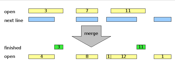
The actual inner loop is similar to the algorithm shown above for the per-pixel updating, but because of the 13 possible relationships between two closed intervals, the inner loop contains a larger case statement; this will not be reproduced here. This new run length transposition algorithm speeds up the overall operation of the binary morphology code several-fold relative to the simple decode-recode implementation.
6 Between Line Boolean Operations
A bit blit based implementation of mathematical morphology uses as its primitive an operation that performs a logical operation (AND, OR, XOR, AND-NOT, OR-NOT, NAND, NOR, etc.) between the pixels of two images, allowing for relative shifts (see also [25]). We can implement the same operations in our library. The general idea is to consider the runs in the two source lines from left to right and merge them together. For example, if the operation is AND, then this means deleting any run in either of the two input lines that does not overlap a corresponding run in the other line. Because of the 13 possible relationships between intervals, this is fairly complicated. However, there is a pair of useful abstractions that greatly simplifies the implementation of these kinds of interval merging operations.666 A similar technique can be applied to the transpose operation above, but that operation was written by considering the different possible cases directly. Basically, instead of considering lines as collections of runs, we consider them as collections of transitions from black to white and from white to black. We operate on those collections using two simple abstractions:
-
•
A TransitionSource returns locations of transitions in ascending order, indicating for each transition whether it is from black to white or from white to black.
-
•
A TransitionSink accepts locations of transitions in ascending order and re-assembles them into intervals.
With these abstractions, the main loop of line_and becomes simply (in C++):
TransitionSink sink(out,total);
TransitionSource src1(l1,0);
TransitionSource src2(l2,offset2);
int where = MININT;
bool b1 = false;
bool b2 = false;
while(src1 || src2) {
    if(src1.coord()<src2.coord()) {
        b1 = src1.value();
        where = src1.coord();
        src1.next();
    } else {
        b2 = src2.value();
        where = src2.coord();
        src2.next();
    }
    sink.append(where,b1&&b2);
}
The simplification of the code results from the fact that the main loop becomes a simple ordered merge of lists of numbers, and the sink data structure takes care of the different cases; for example if it receives a sequence of transitions , it will generate a run from to . Boundary conditions are additionally simplified because the TransitionSource returns a big integer after running out of locations, which eliminates separate code after the main loop to finish off the unfinished line when the other line has run out of transitions.
7 Efficient Binary Decompositions
Binary decomposition of linear structuring elements is a widely used technique for real-world, fast binary morphology. For reviews of the technique, see [19, 4, 15]. We can combine the “bit blit-like” operations above with binary decomposition for an alternative approach to binary morphology on run-length images.
Generally, a linear structuring element of length can be decomposed into
| (1) |
A simple example of this is the decomposition of the structuring element[15]:
| (2) |
This involves 9 pixels, and hence 9 blit operations in a straightforward bit blit implementation. This represents a significant savings over the original 19 pixels of the linear structuring element, but it does not represent the optimal decomposition of a structuring element of 19 pixels, which requires just 5 blit operations:
width = 1;
while(2*width<r) {
    bits_and(image,image,width,0);
    width *= 2;
}
if(width<r) bits_and(image,image,r-width-1,0);
To center the operation properly, we need to shift the image prior to these operations. The overall cost of decomposing a line structuring element therefore is a shift operation plus , where is the width of the structuring element in pixels. In the run length morphology library, this approach is applied to the between-line morphological operations.
An alternative loop avoids the initial shift, which causes some undesirable behavior at the image border. The idea is to perform exponential doubling to cover at least half of the right half of the structuring element, and then finish of the operation with three more operations (overall, this requires one extra blit relative to the simple version above):
width = 1;
while(2*width<r/2) {
    bits_and(image,image,width,0);
    width *= 2;
}
if(width<r/2) bits_and(image,image,r/2-width-1,0);
bits_and(image,image,-(r-r/2),0);
if(width<r-r/2) bits_and(image,image,-(r-r/2)+width,0);
.
8 2D Morphological Operators for Rectangular Masks
Given the three operations developed above, within-line morphological operations, transpose, between-line binary operations, and logarithmic binary decomposition, as well as the separability property of rectangular masks, we now have various different ways of composition 2D morphological operators using rectangular structuring elements:
-
•
“brute force” implementation: this simply performs a shifted AND or OR operation for each pixel in the mask, quite analogous to a brute-force bit blit implementation; this is a slow operation useful for reference and verification
-
•
transpose and within-line operations: we first perform morphology along the within-line direction, then transpose, then perform morphology again, and then transpose back
-
•
within-line and between-line operations: we perform morphology along one direction using the within-line operators, and along the other direction using logarithmic decomposition and between-line operations; this can be carried out in either order
It is not a priori obvious which of these choices is the most efficient, but it turns out experimentally that the last one works fastest for document images. Furthermore, it is important to carry out the within-line operations before the between-line operations because the former are far more efficient when coping with images with many runs. We will return to this issue in the experimental section.
9 Morphology with Arbitrary Masks
Many structuring elements in practice are handled as arbitrary bitmasks, using a straightforward loop such as:
for(i=0;i<w;i++) for(j=0;j<h;j++) {
    if(element(i,j)==0) continue;
    bits_and(result,image,-i+cx,-j+cy);
    count++;
}
Obviously, loops like that grow linearly in the number of pixels in the structuring element.
Fortunately, for run-length encodings, we can perform these operations a run at a time, rather than a pixel at a time. Essentially, for each run in the mask, we perform the operation on a copy of the image, then apply the result to an accumulator image, which we finally return.
for(run in horizontal_runs(element)) {
    temp = copy(image);
    erode_line_horizontal(temp,run.x,run.y0,run.y1);
    bits_and(result,temp)
    count++;
}
Of course, for run length morphology, we can carry out erode_line_horizontal directly.
For bit blit morphology, the naive implementation would use binary decomposition to compute erode_line_horizontal separately for each run. For completeness (and because it is implemented in the companion bit blit-based operations) let us observe that such an approach involves many unnecessary copies and recomputations of intermediate results; the overall complexity is . A better way to perform decomposition of arbitrary masks is to accumulate longer and longer horizontal structuring elements and apply them as needed. The following simple pseudocode illustrates the idea (it assumes that the structuring element has been flipped prior to the computation; maxwidth is the maximum run width):
temp = copy(image);
for(width=1;width<maxwidth;width*=2) {
    for(run in runs_of_element) {
        run_width = run.y1-run.y0;
        if(run_width >= width && run_width < 2*width) {
            bits_and(image,temp,run.x,run.y0);
            if(run_width>width) bits_and(image,temp,run.x,run.y1-run_width-1);
        }
    }
}
For a circle of radius , this involves at most calls to the bits_and function, plus a copy. A separate shift is not needed to center the result since the runs themselves can be offset appropriately.
10 Scaling, Skewing, and Rotation
Scaling, skewing, and rotation are other important operations in document image analysis, used during display and skew correction.
Scaling can be implemented by scaling the coordinates of each run and scaling up or down the array holding the lines by deleting or duplicating line arrays. Scaling can also be implemented as part of the conversion into an unpacked representation (as required by, for example, window systems).
Skew operations can be implemented within each line by shifting the start and end values associated with each run. Bitmap rotation by arbitrary angles can then be implemented by the usual decomposition of rotations into a sequence of horizontal and vertical skew operations, using successive application of transposition, line skewing, and transposition in order to achieve skews perpendicular to the lines in the run-length representation. We note that this method differs substantially from previously published rotation algorithms for run length encoded images [26, 2].
11 Morphology with Lines at Arbitrary Orientations
Finally, let us look at one more case related to lines: morphological operations with linear structuring elements at arbitrary angles. A number of papers have been written about this, using different approaches. Oddly enough, few if any of the papers appear to reference the most obvious approach: bitmap rotation followed by an axis-aligned structuring element; this would at least be an important control experiment [17, 18]:
bits_erode_line(image,r,angle) {
    bits_rotate(image,angle);
    erode_line_horizontal(image,2*r);
    bits_rotate(image,-angle);
}
The rotations can be composed from three skew operations, as for general bitmap rotations. In fact, the same approach also works for rotated rectangles.
However, a rotation of a horizontal line segment will give rise to a rotated line segment whose bits differ slightly from the bits generated by rendering a digital line segment at that angle using the true linear equations or Bresenham’s algorithm. Furthermore, the skew operations dominate this approach to morphological operations with rotated lines.
Fortunately, there is a simpler, pixel accurate solution: we apply only a single skew operation and correct for the change in length. With this, line erosions at arbitrary angles between become (angles outside this range can be handled by flips and trasposes):
bits_erode_line(image,r,angle) {
    skew = tan(angle);
    corrected = r*cos(angle);
    bits_skew(image,skew);
    erode_line_horizontal(image,2*corrected);
    bits_skew(image,-skew);
}
Here, the function bits_skew moves each pixel at to . Note that the skew operation is perpendicular to the erosion. It is likely faster to skew along each line (via bit shifting the line) and then perform the erosion perpendicular to that than the other way around.
12 Conversion Between Image Formats
Conversion to/from run-length encoded representation to either unpacked or packed bit-images is straight-forward. We note that input/output can be implemented particularly efficiently in terms of run-length image representations, since many binary image formats internally already perform some form of run-length compression, and their runs can be directly translated in runs in the in-memory representation. Even for file formats that do not use runs, input/output can be implemented by compressing and decompressing the image one line at a time; that is, we read a line by calling the image decompression library, decode the line in an unpacked format into a 1D array, and then compute the run-length encoding of that array.
13 Connected Component Extraction and Statistics
Connected components, and statistics over them, can also be computed quickly:
-
•
We associate a label value
label[i][j]with each runlines[i][j]. -
•
For each run in the entire image, we create a set in a union-find data structure.
-
•
We then iterate through all the lines in the image and, for each run in the current line merge its label with the labels of any runs in the line above. This can be done in linear time in the number of runs in each line.
-
•
Finally, we renumber the entries in
label[i][j]according to the canonical set representative from the union-find data structure.
This is similar to a connected component algorithm on the line ajacency graph (but the order in which nodes are explored can be different). It is also similar to efficient connected component algorithms operating on bitmap images, but runs are used instead of iterating over the pixels or words.
The output of this process is a set of runs lines[i][j] and corresponding labels label[i][j]. We can also think of these structures together as a run-length compressed image with pixel values stored in the label array. For computing bounding boxes, centroids, moments, boundaries, boundary properties, or other spatial statistics over these regions, we can iterate through the runs and accumulate the corresponding information in accumulator arrays indexed by the labels stored in the label array.
14 Other Operations
There are a number of other operations that can be carried out quickly on run-length representations:
-
•
Run-length statistics are frequently used in document analysis to estimate character stroke widths, word spacings, and line spacings; they can be computed in linear time for both black and white runs by iterating through the runs of an image. In the vertical direction, they can be computed by first transposing the image.
-
•
The line adjacency graph can be computed by treating the runs as nodes in the graph and creating edges between any runs in adjacent lines if the intervals represented by the runs overlap.
-
•
Standard skeletonization methods for the line adjaceny graph can be applied after computation of the LAG as described above. (See also [16].)
-
•
Run-length based extraction of lines and circles using the RAST algorithm [12] can be applied directly.
15 Experiments
We have implemented, among others, conversions between run-length, packed bit, and unpacked bit representations of binary images, transposition, all the morphological operations with rectangular structuring elements described above, bitmap rotation by arbitrary angles, computation of run-length statistics, connected component labeling, and bounding box extraction. For evaluating the general behavior of these algorithms and determining whether they are feasible in practice, we are comparing the performance of the run-length based algorithms with a companion binary bit blit based morphology package, as well as the bitmap-based binary morphology implementation in Leptonica 1.48 (8/30/07), an open source morphological image processing library in use in production code and containing well-documented algorithms and implementations [4, 5].
Leptonica contains multiple implementations of binary morphology; the fastest general-purpose implementation is pixErodeCompBrick (and analogous names for other operations), a method that uses separability and binary decomposition; it was used unless otherwise stated. Leptonica also contains partially evaluated morphology operators for a number of specific small mask sizes available under the names like pixErodeBrickDwa. These were used when applicable. Both libraries were compiled with their default (optimized) settings.
In the experiments, we want to address several questions:
-
•
What is the scaling behavior of the run length methods?
-
•
Which of the possible different run length implementations is better?
-
•
Is any one method uniformly better than the others, or do we need to perform algorithm selection?
-
•
How do these algorithms perform for the types of mask sizes and images found in typical document analysis tasks?
15.1 2D Rectangular Masks
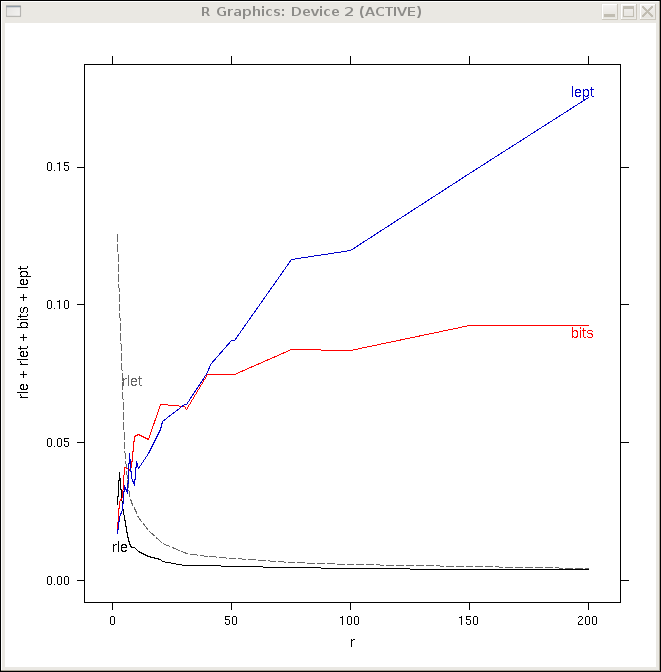
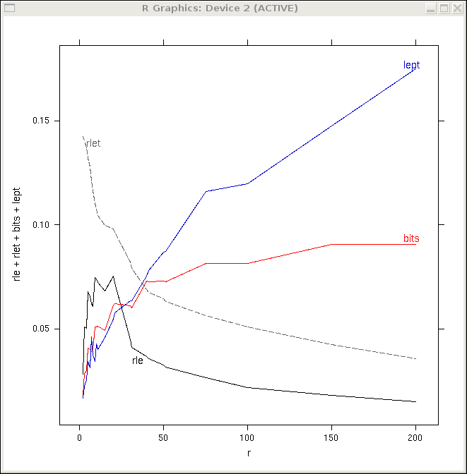
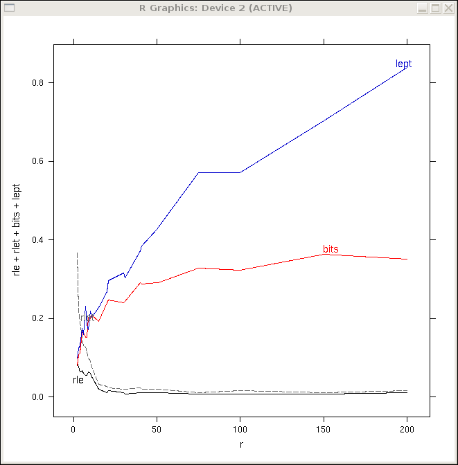
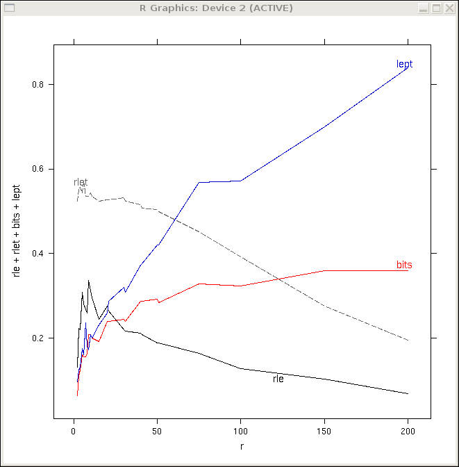
To gain some general insights into the behavior of the run length methods for real-world document images, the running times of morphological operations on the 1600 images of the UW3 [11] database, 300 dpi binary images of scans of degraded journal publication pages, were measured. The results are shown in Figure 2. We see that, except for masks of size five or below, the run length implementation outperforms the bit blit implementation.
By choosing at runtime between the bit blit implementation and the run length implementation, we can obtain a method that shares the characteristics of both kinds of images. As already noted above, the cross-over point can be determined automatically either based on mask size and dpi, or based on output complexity. This is shown as the bold curve in the figures; the curve does not coincide the bit blit based running times because the run length figures include the conversion times from run length representations to packed bit representations and back to run length representations; in many applications, these conversion costs can be eliminated. By switching back to bit blit-based implementations for small mask sizes, we can combine the two methods into a method that gives performance closer to bit blit implementations at small sizes while still retaining the advantages of run length methods at large sizes.
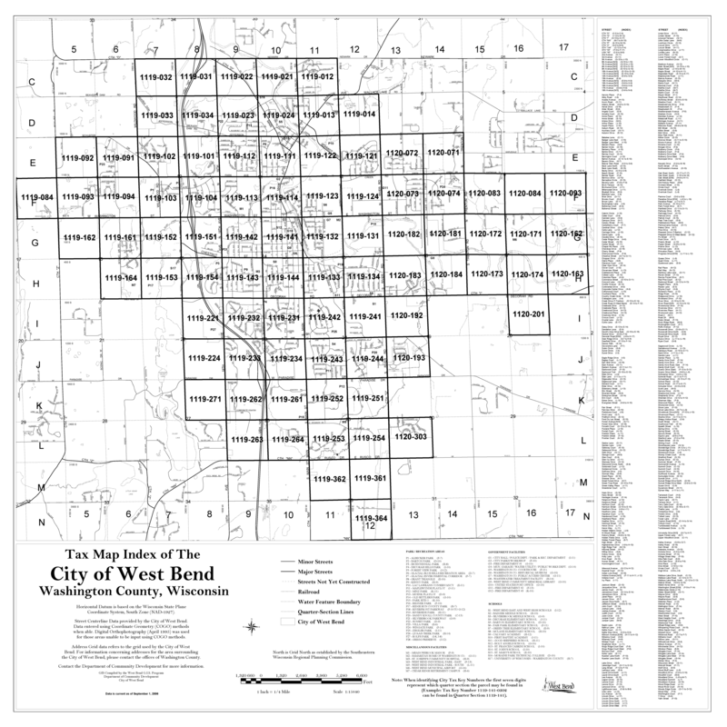
In a second experiment, we compared performance of the run length method to Leptonica’s bit-blit based morphology on a different document type with a binarized pixel cadastral map (Figure 4).
15.2 Circular Masks
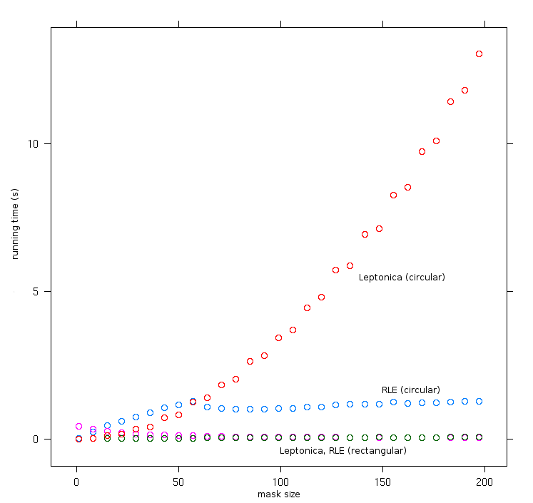
As an illustration of the kind of performance achievable using the run length methods for general purpose structuring elements, Figure 5 shows the performance on circular and rectangular structuring elements using run-length and brute force bit blit morphology.
As expected, the time for the brute force bit blit morphology grows quadratically in the size of the structuring element. Run length morphology grows linearly up to a point where the output complexity (the number of runs in the output image) starts decreasing and dominates the running time.
15.3 Document Analysis Performance
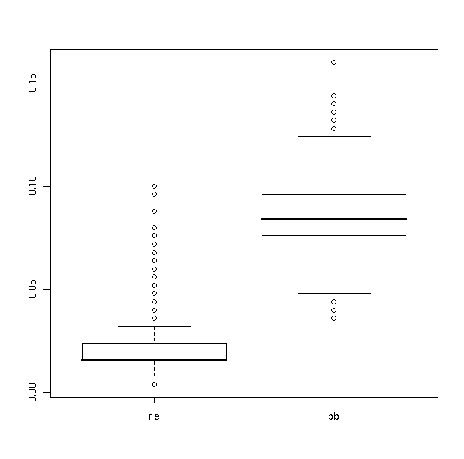
In the third experiment, we want to illustrate overall performance of run length morphology methods as part of a simple morphological layout analysis system. The method estimates the inter-word and inter-line spacing of document images based on black and white run lengths, then performs erosion operations to smear together connected components that are likely to be part of the same blocks based on those estimates, and finally computes the bounding boxes of the resulting large connected components; this approach is similar to the one in [23] As the input, the 1600 pages from the UW3 database were used. These are 300dpi letter sized page images scanned from published journals. Relative performance of the run-length based method and Leptonica’s bit blit based method, including bounding box extraction, are shown in Figure 6. The results show that run length morphological algorithms perform about twice as fast at 300dpi than the bit blit based algorithms in Leptonica (at 600dpi or 1200dpi, the advantage of run length methods would be greater still).
16 Discussion
The paper describes a number of methods used in our open source binary morphology library for performing morphological and related operations on run length representations. Although there is considerable overlap with previously published results, some algorithmic details appear to be not well known, like the use of skew operations for linear structuring elements, and the application of run-length like decompositions and doubling for bit blit based morphology with arbitrary structuring elements. We hope that these methods and implementations will become a useful reference implementation for other work, as well as a practical library for performing binary morphology on document images.
The performance measurements on real-world document images over a wide range of mask sizes, as well as the performance evaluation in the context of a complete layout analysis system demonstrate clearly that the run length morphology is an efficient alternative to bit blit based morphology for realistic document images. Furthermore, comparing 300dpi page images and performance on larger cadastral maps, as well as theoretical considerations, suggest that the advantage of run length methods increases as the size and resolution of images increases.
The algorithms described in this paper were developed originally for document image applications and have proven useful in a variety of practical applications in the years since. Although it is difficult to establish formally, generally, run length based algorithms seem to be somewhat easier to implement efficiently than bit blits, since the boundary conditions and special cases seem to be simpler and fewer. Furthermore, run length morphology has no machine word size dependencies.
It will remain for future work to see how the algorithms presented in this paper relate to methods recently proposed in the literature. Van Droogenbroeck [7], for example, also describes two algorithms using list or rectangular structures to aid in the computation of fast binary morphology. It appears that his methods are considerably more complex to implement. Benchmarking and comparison of these new methods (including the ones presented in this paper) will have to take into account both space and running times, since both are crucial in practical applications. Unlike high performance bit blit methods, these new methods are also sensitive to the complexity of both the input and output. Van Droogenbroeck also raises the issue of implementation complexity; while this is hard to quantify, it appears that the run length methods described in this paper are easier to implement. All these approaches are a trend to taking advantage of coherence in images, similar to the way compression algorithms do.
There are a number of obvious directions for extensions. Operations on arbitrary morphological masks can be represented as run length images as well, and morphology over them can be carried out using similar approaches to those described here. All the accesses within the inner loops of these algorithms are sequential; this presents opportunities for more compact representations, such as variable length multi-byte encodings of run lengths (since shorter run lengths tend to be more frequent than longer run lengths). In fact, even Huffman coding or in-memory zlib compression for each run are possible.
Let us conclude by examining how these results can be used in practice. Run length morphological operations can be incorporated into systems in various ways: (1) a system can use RLE representations and temporarily convert to bitmaps when there is a performance advantage (taking into account the conversion costs), (2) a system can use bitmaps as its primary representation and temporarily switch to RLE when it speeds things up, (3) a system can keep everything in RLE format, or (4) a system can continue to keep everything in bitmap format. It’s clear that, provided the system selects the correct algorithm automatically, (2) is no worse than (4) and that (1) no worse than (3) in terms of performance, and the paper has, in fact, given examples of speedups using such mixed approaches. The experiments presented above on a simple layout analysis system also suggest (but don’t conclusively prove) that (3) may be faster than (4) on average in real-world applications. The question of whether (1) or (2) is faster for real-world applications remains to be determined. Many real-world imaging applications, such as printing engines, already use run length representations internally, and the methods presented in this paper give them the ability to integrate and perform morphological operations directly and efficiently. Existing bitmap-based libraries like Leptonica may want to choose approach (2) to improve performance on large masks without affecting software using the library. Furthermore, the run length conversion and operations can be incorporated directly into a blit-like operation, resulting in a hybrid approach; this will be explored elsewhere. Overall, run length approaches to binary morphology give us another useful option for implementing morphological operations efficiently, in particular in document imaging applications.
Acknowledgements
The author would like Dan Bloomberg, Laurant Najman, Daniel Keysers, and Christian Kofler for valuable suggestions and discussions.
References
- [1] Karen L. Anderson and Joan L. Michell. System for creating transposed image data from a run end or run length encoded image. U.S. Patent #4783834, 1988.
- [2] Ka Man Au and Zaioxun Zhu. Skew processing of raster scan images. U.S. Patent #6490376, 2002.
- [3] H. S. Baird, S. E. Jones, and S. J. Fortune. Image segmentation by shape-directed covers. In Proceedings of the Tenth International Conference on Pattern Recognition, Atlantic City, New Jersey, pages 820–825, 1990.
- [4] D. S. Bloomberg. Implementation efficiency of binary morphology. In International Symposium on Mathematical Morphology VI, 2002.
- [5] D. S. Bloomberg. The Leptonica library. http://www.leptonica.com/, 2007.
- [6] A. K. Das and B. Chanda. A fast algorithm for skew detection of document images using morphology. International Journal on Document Analysis and Recognition, pages 109–114, 2001.
- [7] M. Van Droogenbroeck. Algorithms for openings of binary and label images with rectangular structuring elements. In Mathematical Morphology: Proceedings of the 6th International Symposium (ISMM), 2002.
- [8] M. Van Droogenbroeck and M. Buckley. Morphological erosions and openings: fast algorithms based on anchors. Journal of Mathematical Imaging and Vision, Special Issue on Mathematical Morphology after 40 Years, 22(2–3):121–142, 2005.
- [9] J. Gil and R. Kimmel. Efficient dilation, erosion, opening, and closing algorithms. IEEE Trans. on Pattern Analysis and Machine Intelligence, 24(12):1606–1616, 2002.
- [10] J. Gil and M. Werman. Computing 2D min, median, and max filters. IEEE Trans. on Pattern Analysis and Machine Intelligence, pages 504–507, 1993.
- [11] I. Guyon, R. M. Haralick, J. J. Hull, and I. T. Phillips. Data sets for OCR and document image understanding research. In H. Bunke and P. Wang, editors, Handbook of character recognition and document image analysis, pages 779–799. World Scientific, Singapore, 1997.
- [12] Daniel Keysers and Thomas M. Breuel. Optimal line and arc detection on run-length representations. In Proceedings Graphics Recognition Workshop, LNCS. Springer, 2006.
- [13] Ji Liang, J. Piper, and Jing-Yan Tang. Erosion and dilation of binary images by arbitrary structuring elements using interval coding. Pattern Recognition Letters, 9(3), 1989.
- [14] Vishal Misra, Juan F Arias, and Atul K Chhabra. A memory efficient method for fast transposing run-length encoded images. In Proceedings of the Fifth International Conference on Document Analysis and Recognition (ICDAR), page 161, 1999.
- [15] L. Najman. Using mathematical morphology for document skew estimation. In Proc. SPIE Document Recognition and Retrieval XI, volume 5296, pages 182–191, 2004.
- [16] J. Piper. Interval skeletons. In 11th IAPR International Conference on Pattern Recognition, 1992.
- [17] P. Soille, E. J. Breen, and R. Jones. Recursive implementation of erosions and dilations along discrete lines at arbitrary angles. PAMI, 18(5):562–567, 1996.
- [18] P. Soille and H. Talbot. Directional morphological filtering. Pattern Analysis and Machine Intelligence, IEEE Transactions on, 23(11):1313–1329, 2001.
- [19] Rein van den Boomgaard and Richard van Balen. Methods for fast morphological image transforms using bitmapped binary images. CVGIP: Graphical Models and Image Processing, 54(3):252–258, 1992.
- [20] Marcel van Herk. A fast algorithm for local minimum and maximum filters on rectangular and octagonal kernels. Pattern Recognition Letters, 13(7):517–521, 1992.
- [21] B. J. H. Verwer and L. J. van Vliet. A contour processing method for fast binary neghbourhood operations. Pattern Recognition Lett., 7:27–36, 1988.
- [22] Luc Vincent. Morphological algorithms. In Mathematical Morphology in Image Processing (E. Dougherty, editor), pages 255–288. Marcel-Dekker, New York, 1992.
- [23] K. Y. Wong, R. G. Casey, and F. M. Wahl. Document analysis system. IBM Journal of Research and Development, 26(6):647–656, 1982.
- [24] X. Ye, M. Cheriet, and Ching Y. Suen. A generic method of cleaning and enhancing data from business forms. International Journal on Document Analysis and Recognition, pages 84–96, 2001.
- [25] I. T. Young, R. L. Peverini, P. W. Verbeek, and P. J. van Otterloo. A new implementation for the binary and minkowski operators. Computer Graphics and Image Processing, 17:189–210, 1981.
- [26] Jie Zhu, Michael C. Moed, and Izrail S. Gorian. Method and system for fast rotation of run-length encoded images. U.S. Patent #5581635, 1995.