Optical spin-to-orbital angular momentum conversion in inhomogeneous anisotropic media
Abstract
We demonstrate experimentally an optical process in which the spin angular momentum carried by a circularly polarized light beam is converted into orbital angular momentum, leading to the generation of helical modes with a wavefront helicity controlled by the input polarization. This phenomenon requires the interaction of light with matter that is both optically inhomogeneous and anisotropic. The underlying physics is also associated with the so-called Pancharatnam-Berry geometrical phases involved in any inhomogeneous transformation of the optical polarization.
pacs:
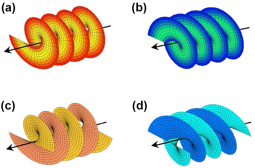
42.25.-p,42.60.Jf,42.81.Gs,42.79.-eA monochromatic light beam travelling along a given axis can transport angular momentum oriented as the propagation direction in two different forms Humblet (1943); Abbate et al. (1991); Allen et al. (1992). The first is the classical “spin-like” form associated with the circular polarizations of light, each photon carrying of angular momentum depending on the handedness of the polarization. The second is an “orbital” form, associated with the optical phase profile of the beam in a plane orthogonal to the propagation axis, i.e. parallel to the plane. Using a complex notation footnote1 , the electric field of a beam carrying a well defined value of the orbital angular momentum can be written as , where are polar coordinates in the plane and is an integer. For such a field, commonly named a “helical mode”, it has been shown that each photon carries a quantized intrinsic orbital angular momentum (-component) given by Allen et al. (1992, 1999); O’Neil et al. (2002). The wavefront of this field is composed of intertwined helical surfaces, with a handedness given by the sign of , as shown in Fig. 1. Moreover, these fields present a topological phase singularity (an “optical vortex”) at the beam axis Nye and Berry (1974); Bazhenov et al. (1990). For definiteness, in the following we will refer to as the orbital-helicity of the beam (also called “charge” of the vortex). In general, any optical wave can be decomposed in circularly polarized helical modes carrying well defined values of both spin and orbital angular momentum. A particularly important example is that given by the Laguerre-Gaussian set of modes, which are exact eigenmodes of the wave equation in the paraxial approximation (Helmholtz equation).
When light propagates in vacuum or in a homogeneous and isotropic transparent medium, both spin and orbital angular momentum are separately conserved. Both forms of angular momentums can be however transferred to matter in suitable conditions. When a photon is absorbed, for example, it transfers all its angular momentum to the absorbing particle, both spin and orbital He et al. (1995); Simpson et al. (1997). However, the two forms of optical angular momentum may couple to different material degrees of freedom, when the particle is located off axis O’Neil et al. (2002). Transfer of spin-only angular momentum to matter is achieved in optically anisotropic media, as in normal birefringent wave plates Beth (1936), trapped microscopic particles Friese et al. (1998), and liquid crystals Santamato et al. (1986); Abbate et al. (1991); Marrucci et al. (1992). An independent coupling of orbital-only angular momentum with matter is instead possible in inhomogeneous isotropic transparent media Beijersbergen et al. (1993, 1994) (see also the related demonstration of optical manipulation of particles with helical beams Paterson et al. (2001)).
Clearly, a simultaneous independent coupling of both the spin and orbital forms of angular momentum of light with matter is to be expected in a medium which is both inhomogeneous and anisotropic Piccirillo and Santamato (2004). As we show in the following, these two separate channels of angular momentum exchange between light and matter do indeed exist in these optical media, but unexpectedly they are not independent at all: in appropriate conditions, the exchange with matter of the spin optical angular momentum affects the direction (sign) of the exchange of the orbital angular momentum. There are even specific geometries in which the two exchanges remain always exactly opposite to each other, so that the total angular momentum transferred to matter (the optical torque) vanishes identically. In these cases, a direct transformation of the optical angular momentum from the spin form to the orbital form takes place, with matter playing only an intermediate role. We note that this is a rather counterintuitive process, in which the input polarization of light controls the shape of the output wavefront.
To illustrate these effects, let us consider the specific case of a planar slab of a uniaxial birefringent medium, having an homogeneous birefringent phase retardation of (half-wave) across the slab, and an inhomogeneous orientation of the fast (or slow) optical axis lying parallel to the slab planes. We assume that the light beam impinges on the slab at normal incidence, so that the slab planes are parallel to the coordinate plane. Moreover, the optical axis orientation in the plane, as specified by the angle it forms with the axis, is assumed to be given by the following equation:
| (1) |
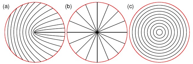
where and are constants. Equation (1) implies the presence of a defect in the medium localized at the plane origin, , similar to the typical defects spontaneously formed by nematic liquid crystals de Gennes (1974). However, if is an integer or a semi-integer there will be no discontinuity line in the slab. In the following, we will refer to inhomogeneous birefringent elements having the above specified geometry as -plates. A few examples of -plate geometries for different values of and are shown in Fig. 2.
To analyze the effect of a -plate on the optical field, it is convenient to adopt a Jones formalism. The Jones matrix to be applied on the field at each point of the -plate transverse plane is the following:
| (2) |
where is the standard rotation matrix by angle (in the plane), and it is understood that depends on the point in the transverse plane according to Eq. (1).
A left-circular polarized plane wave, described by the Jones electric-field vector , after passing through the -plate, will be transformed into the following outgoing wave (up to an unimportant overall phase shift):
| (3) |
The wave emerging from the -plate is therefore uniformly right-circular polarized, as would occur for a normal half-wave plate, but it has also acquired a phase factor with , i.e. it has been transformed into a helical wave with orbital helicity and orbital angular momentum per photon. It is easy to verify that in the case of a right-circular input wave, the orbital helicity and angular momentum of the outgoing wave are sign-inverted. In other words, the input polarization of the light controls the sign of the orbital helicity of the output wavefront. Its magnitude is instead fixed by the birefringence axis geometry.
In passing through the plate, each photon being converted from left-circular to right-circular changes its spin -component angular momentum from to . In the case of a -plate having , the orbital -component angular momentum of each photon changes instead from zero to . Therefore, the total variation of the angular momentum of light is nil and there is no net transfer of angular momentum to the plate: the plate in this case acts only as a “coupler” of the two forms of optical angular momentum, allowing their conversion into each other. This exact compensation of the spin and orbital angular momentum exchanges with matter is clearly related to the circular symmetry (rotation invariance) of the plate, as can be proved by general energy arguments or by a variational approach to the optical angular momentum fluxes Abbate et al. (1991). If , the plate is not symmetric and will exchange an angular momentum of with each photon, with a sign depending on the input polarization. Therefore, in this general case the angular momentum will not be just converted from spin to orbital, but the spin degree of freedom will still control the “direction” of the angular momentum exchange with the plate, besides the sign of the output wavefront helicity.
To demonstrate these optical phenomena, we built a -plate with using nematic liquid crystal (LC) as the birefringent material. The LC was sandwiched between two plane glasses, thus forming a planar cell. The LC cell thickness (about 1 m) and material (E63 from Merck, Darmstadt, Germany) were chosen so as to obtain a birefringence retardation of approximately a half wave, at the working wavelength nm. Before assembly, the inner surfaces of the two glasses were coated with a polyimide for planar alignment and one of them was briefly pressed against a piece of fabric kept in continuous rotation. This procedure led to a surface easy axis (i.e., the preferred orientation of LC molecules) having the desired circular-symmetric geometry, as that shown in Fig. 2, panel (c).
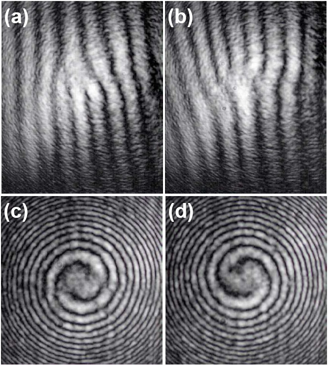
In order to measure the wavefront shape of the light emerging from the -plate, we set up a Mach-Zender interferometer. A He-Ne laser beam with a TEM00 gaussian profile was split in two beams, namely signal and reference. The signal beam was first circularly polarized with the desired handedness by means of properly oriented quarter-wave plate and then was sent through the LC -plate. The beam emerging from the -plate was then sent through another quarter-wave plate and a linear polarizer, arranged for transmitting the polarization handedness opposite to the initial one, so as to eliminate the residual unchanged circular polarization (this step is not necessary when using a -plate having exactly half-wave retardation). Finally, the signal beam was superimposed with the reference and thus generated an interference pattern directly on the sensing area of a CCD camera. We used two different interference geometries. In the first, the reference beam wavefront was kept approximately plane (more precisely, it had the same wavefront curvature as the signal beam) but the two beams were slightly tilted with respect to each other. For non-helical waves, this geometry gives rise to a regular pattern of parallel straight fringes. If the wavefront of the signal beam is helical, the pattern develops a dislocation (double, in this case, since yields ), with an orientation depending on the sign of and the relative orientation of the two beams. In the second geometry, the reference beam wavefront was approximately spherical, as obtained by inserting a lens in the reference arm. For non-helical waves, the resulting interference pattern is made of concentric circular fringes. If the wavefront of the signal beam is helical, the pattern takes instead the form of a spiral (a double spiral, for ), with a handedness depending on the sign of (counterclockwise outgoing spirals, seen against the propagation direction as in our case, correspond to a positive ). Figure 3 shows the CCD-acquired images of the interference patterns we obtained in the two geometries, respectively for a left-circular (panels (a) and c)) and right-circular (panels (b) and (d)) input polarizations. These results show unambiguously that the wavefront of the light emerging from the -plate is indeed helical with (i.e. as shown in panels (c) and (d) of Fig. 1), as predicted, and that it carries an orbital angular momentum just opposite to the variation of spin angular momentum associated with the polarization occurring in the plate.
It must be emphasized that all commonly used methods for generating helical modes of light (cilindrical lenses Allen et al. (1992); Beijersbergen et al. (1993), spiral plates Beijersbergen et al. (1994) and holographic elements Bazhenov et al. (1990)) are associated exclusively with an exchange of orbital angular momentum of light with matter (indeed, they all involve inhomogeneous isotropic media) and do not involve the wave polarization at all. In all these methods the chirality of the medium structure is imprinted on the generated wavefront, whose orbital helicity is therefore fixed (although holographic spatial light modulators allow a slow dynamical control of the generated helicity, by modifying the medium spatial structure). In contrast, in the angular momentum conversion process described here, the chirality of the generated wavefront is determined by the input polarization handedness, and can therefore be easily controlled dynamically.
The generation of electromagnetic helical waves based on spatially non-uniform polarization transformations was previously reported by Biener et al., who used subwavelength diffraction gratings as birefringent elements and therefore were limited to the mid-infrared spectral domain Biener et al. (2002); Niv et al. (2005). However, Biener et al. did not discuss the conversion of optical angular momentum involved in the process. Moreover, the interference geometry adopted by Biener et al. did not allow distinguishing between right- and left-handed helical wavefronts and therefore did not allow measuring the sign of the associated orbital angular momentum. For this reason, the results reported here provide to our knowledge the first actual demonstration of the all-optical spin-to-orbital angular momentum conversion process, as well as the first demonstration of the sign-inversion of the generated orbital helicity occurring upon switching the input polarization handedness.
Biener et al. highlighted another general physical principle at the root of these optical phenomena: different polarization transformations having the same initial and final states involve optical phase differences of a geometrical nature, known as Pancharatnam-Berry phases Pancharatnam (1956); Berry (1987). This principle is actually not limited to the generation of helical waves, but it can be extended to any wavefront shaping controlled by polarization transformations, thus setting the basis for an entirely new approach to the design of phase optical elements Bhandari (1997); Bomzon et al. (2002), an approach of which our work represents the first actual demonstration in the visible domain.
In conclusion, we identified and experimentally demonstrated for the first time an optical process in which the direct conversion of optical angular momentum from the spin to the orbital form takes place. This process leads to the generation of helical modes of light with a wavefront helicity controlled by the input polarization. This approach to the generation of helical modes of light could prove particularly valuable in the foreseen applications of these modes to the multi-state information encoding for classical Gibson et al. (2004) and quantum communication and computation Molina-Terriza et al. (2002); Leach et al. (2002); Vaziri et al. (2002), where the capability for a fast switching of the generated helicity is critical.
We are grateful to Istvan Jánossy for a stimulating scientific discussion which led us to conceiving this work, and to Enrico Santamato and Giancarlo Abbate for lending us some experimental equipment and for introducing us to the subject of the angular momentum of light.
References
- Humblet (1943) J. Humblet, Physica 10, 585 (1943).
- Abbate et al. (1991) G. Abbate, P. Maddalena, L. Marrucci, L. Saetta, and E. Santamato, Phys. Scripta T39, 389 (1991).
- Allen et al. (1992) L. Allen, M. W. Beijersbergen, R. J. C. Spreeuw, and J. P. Woerdman, Phys. Rev. A 45, 8185 (1992).
- (4) We adopt the sign convention of the wave propagation factor , which in turn fixes the sign-convention on the wave orbital helicity and angular momentum.
- Allen et al. (1999) L. Allen, M. J. Padgett, and M. Babiker, Prog. Opt. 39, 291 (1999).
- O’Neil et al. (2002) A. T. O’Neil, I. MacVicar, L. Allen, and M. J. Padgett, Phys. Rev. Lett. 88, 053601 (2002).
- Nye and Berry (1974) J. F. Nye and M. V. Berry, Proc. Roy. Soc. Lond. A 336, 165 (1974).
- Bazhenov et al. (1990) V. Y. Bazhenov, M. V. Vasnetsov, and M. S. Soskin, JETP Lett. 52, 429 (1990).
- He et al. (1995) H. He, M. E. J. Friese, N. R. Heckenberg, and H. Rubinsztein-Dunlop, Phys. Rev. Lett. 75, 826 (1995).
- Simpson et al. (1997) N. B. Simpson, K. Dholakia, L. Allen, and M. Padgett, Opt. Lett. 22, 52 (1997).
- Beth (1936) R. A. Beth, Phys. Rev. 50, 115 (1936).
- Friese et al. (1998) M. E. J. Friese, T. A. Nieminen, N. R. Heckenberg, and H. Rubinsztein-Dunlop, Nature 394, 348 (1998).
- Santamato et al. (1986) E. Santamato, B. Daino, M. Romagnoli, M. Settembre, and Y. R. Shen, Phys. Rev. Lett. 57, 2423 (1986).
- Marrucci et al. (1992) L. Marrucci, G. Abbate, S. Ferraiuolo, P. Maddalena, and E. Santamato, Phys. Rev. A 46, 4859 (1992).
- Beijersbergen et al. (1993) M. W. Beijersbergen, L. Allen, H. E. L. O. van der Veen, and J. P. Woerdman, Opt. Commun. 96, 123 (1993).
- Beijersbergen et al. (1994) M. W. Beijersbergen, R. P. C. Coerwinkel, M. Kristensen, and J. P. Woerdman, Opt. Commun. 112, 321 (1994).
- Paterson et al. (2001) L. Paterson, M. P. MacDonald, J. Arlt, W. Sibbett, P. E. Bryant, and K. Dholakia, Science 292, 912 (2001).
- Piccirillo and Santamato (2004) B. Piccirillo and E. Santamato, Phys. Rev. E 69, 056613 (2004).
- de Gennes (1974) P. G. de Gennes, The Physics of Liquid Crystals (Oxford University Press, Oxford, 1974).
- Biener et al. (2002) G. Biener, A. Niv, V. Kleiner, and E. Hasman, Opt. Lett. 27, 1875 (2002).
- Niv et al. (2005) A. Niv, G. Biener, V. Kleiner, and E. Hasman, Opt. Commun. 251, 306 (2005).
- Pancharatnam (1956) S. Pancharatnam, Proc. Indian Acad. Sci. Sect. A 44, 247 (1956).
- Berry (1987) M. V. Berry, J. Mod. Opt. 34, 1401 (1987).
- Bhandari (1997) R. Bhandari, Phys. Rep. 281, 1 (1997).
- Bomzon et al. (2002) Z. Bomzon, G. Biener, V. Kleiner, and E. Hasman, Opt. Lett. 27, 1141 (2002).
- Gibson et al. (2004) G. Gibson, J. Courtial, M. J. Padgett, M. Vasnetsov, V. Pas’ko, S. M. Barnett, and S. Franke-Arnold, Opt. Express 12, 5448 (2004).
- Molina-Terriza et al. (2002) G. Molina-Terriza, J. P. Torres, and L. Torner, Phys. Rev. Lett. 88, 013601 (2002).
- Leach et al. (2002) J. Leach, M. J. Padgett, S. M. Barnett, S. Franke-Arnold, and J. Courtial, Phys. Rev. Lett. 88, 257901 (2002).
- Vaziri et al. (2002) A. Vaziri, G. Weihs, and A. Zeilinger, Phys. Rev. Lett. 89, 240401 (2002).