On features of the radiation from an electron moving along a helix inside a cylindrical hole in a homogeneous dielectric

S. R. Arzumanyan, L. Sh. Grigoryan, H. F. Khachatryan    A. S. Kotanjyan, A. A. Saharian
Institute of Applied Problems in Physics, National Academy of Sciences
25 Hr. Nersessian Street, 0014 Yerevan, Armenia
Email address: saharian@ictp.it
Abstract

The radiation from a charge moving along a helical trajectory inside a cylindrical hole in homogeneous dielectric medium is investigated. Prompted by availability of materials with large dielectric permittivity Ξ΅πœ€\varepsilon and small absorption, we discuss the features of this type of radiation for media with Ρ≫1much-greater-thanπœ€1\varepsilon\gg 1. It is shown that there are high peaks in the angular distribution of radiation intensity at well-defined harmonics. The conditions are specified for the cavity-to-helix radii ratio, ρ1/ρ0subscript𝜌1subscript𝜌0\rho_{1}/\rho_{0}, under which the angle-integrated radiation intensity on some harmonics exceeds that in the empty space. Though the amplification of radiation intensity increases with increasing Ξ΅πœ€\varepsilon, the corresponding ”resonant” values of ρ1/ρ0subscript𝜌1subscript𝜌0\rho_{1}/\rho_{0} ratio are practically independent of the dielectric permittivity of surrounding medium. It is shown that an analogous amplification of radiation takes place essentially for the same values of ρ1/ρ0subscript𝜌1subscript𝜌0\rho_{1}/\rho_{0} also for the radiation in a cylindrical waveguide with conducting walls. An explanation of this phenomenon is given.


PACS number(s): 41.60.Ap, 41.60.Bq

Keywords: Synchrotron radiation, helical undulators


1 Introduction

The radiation from a charged particle moving along a helical orbit in vacuum has been widely discussed in literature (see, for instance, [1, 2] and references given therein). This type of electron motion is used in helical undulators for generating electromagnetic radiation in a narrow spectral interval at frequencies ranging from radio or millimeter waves to X-rays. The unique characteristics, such as high intensity and high collimation, have resulted in extensive applications of this radiation in a wide variety of experiments and in many disciplines. These applications motivate the importance of investigations for various mechanisms of controlling the radiation parameters. From this point of view, it is of interest to consider the influence of a medium on the spectral and angular distributions of the radiation.

In Ref. [3] we have investigated the radiation by a charged particle moving along a helical orbit inside a dielectric cylinder immersed into a homogeneous medium. Specifically, formulae are derived for the electromagnetic fields and for the spectral-angular distribution of the radiation intensity in the exterior medium. It is shown that under the Cherenkov condition for dielectric permittivity of the cylinder and the velocity of the particle image on the cylinder surface, strong narrow peaks are present in the angular distribution for the number of radiated quanta. At these peaks the radiated energy exceeds the corresponding quantity for a homogeneous medium by some orders of magnitude. A special case of the relativistic motion along the direction of the cylinder axis with non-relativistic transverse velocity is discussed in detail and various regimes for the undulator parameter are considered. The electromagnetic fields generated inside the cylinder by the charge moving along a helical orbit are considered in [4]. Note that the properties of the radiation from a charged particle moving along a helical orbit in homogeneous dispersive medium are studied in [5]. In the present paper we give the results of the further investigation of the radiation features for a charge moving along a helix inside a cylindrical hole in a homogeneous medium. We also compare this results with the radiation properties in the case when the particle moves with helical trajectory inside a cylindrical waveguide with conducting walls [6, 7].

2 Radiation from a charge moving inside a cylindrical hole in a homogeneous medium

Consider a point charge qπ‘žq moving along the helical trajectory of radius ρ0subscript𝜌0\rho_{0} inside a cylindrical hole with radius ρ1subscript𝜌1\rho_{1} in a homogeneous medium with dielectric permittivity Ξ΅πœ€\varepsilon (for simplicity the magnetic permeability is taken to be unit). The particle velocities along the axis of the hole (drift velocity) and in the perpendicular plane we will denote by vβˆ₯subscript𝑣parallel-tov_{\parallel} and vβŸ‚subscript𝑣perpendicular-tov_{\perp}, respectively. In a properly chosen cylindrical coordinate system (ρ,Ο•,z𝜌italic-ϕ𝑧\rho,\phi,z) the corresponding motion is described by the coordinates ρ=ρ0𝜌subscript𝜌0\rho=\rho_{0}, Ο•=Ο‰0​titalic-Ο•subscriptπœ”0𝑑\phi=\omega_{0}t, z=vβˆ₯​t𝑧subscript𝑣parallel-to𝑑z=v_{\parallel}t, where the z𝑧z-axis coincides with the hole axis and Ο‰0=vβŸ‚/ρ0subscriptπœ”0subscript𝑣perpendicular-tosubscript𝜌0\omega_{0}=v_{\perp}/\rho_{0} is the angular velocity of the charge. This type of motion can be produced by a uniform constant magnetic field directed along the axis of a cylinder, by a circularly polarized plane wave, or by a spatially periodic transverse magnetic field of constant absolute value and a direction that rotates as a function of the coordinate z𝑧z.

In [3] it have been investigated the radiation by a charged particle moving along a helical orbit inside a dielectric cylinder immersed into a homogeneous medium. Now we turn to the investigation of the features of the radiation intensity to the exterior medium at a given harmonic mπ‘šm in the case when the particle moves along helical trajectory inside a cylindrical hole in dielectric medium with the dielectric permittivity Ρ≫1much-greater-thanπœ€1\varepsilon\gg 1. At large distances from the charge trajectory the dependence of elementary waves on the space-time coordinates has the form exp⁑[i​ωm​Ρ​(ρ​sin⁑ϑ+z​cosβ‘Ο‘βˆ’c​t/Ξ΅)/c]𝑖subscriptπœ”π‘šπœ€πœŒitalic-ϑ𝑧italic-Ο‘π‘π‘‘πœ€π‘\exp[i\omega_{m}\sqrt{\varepsilon}(\rho\sin\vartheta+z\cos\vartheta-ct/\sqrt{\varepsilon})/c] which describes the wave with the frequency

Ο‰m=m​ω0|1βˆ’vβˆ₯​Ρ​cos⁑ϑ/c|,subscriptπœ”π‘šπ‘šsubscriptπœ”01subscript𝑣parallel-toπœ€italic-ϑ𝑐\omega_{m}=\frac{m\omega_{0}}{|1-v_{\parallel}\sqrt{\varepsilon}\cos\vartheta/c|}, (1)

propagating at the angle Ο‘italic-Ο‘\vartheta to the z𝑧z-axis. The number of the radiated quanta per period of a particle rotation for the harmonic mβ‰ 0π‘š0m\neq 0 is given by the formula (see [3])

d​Nmd​Ω=q2​m​Ρπ2​ℏ​c​|1βˆ’vβˆ₯​Ρ​cos⁑ϑ/c|2​{|Dm(1)βˆ’Dm(βˆ’1)|2+|Dm(1)+Dm(βˆ’1)|2​cos2⁑ϑ}.𝑑subscriptπ‘π‘šπ‘‘Ξ©superscriptπ‘ž2π‘šπœ€superscriptπœ‹2Planck-constant-over-2-pi𝑐superscript1subscript𝑣parallel-toπœ€italic-ϑ𝑐2superscriptsuperscriptsubscriptπ·π‘š1superscriptsubscriptπ·π‘š12superscriptsuperscriptsubscriptπ·π‘š1superscriptsubscriptπ·π‘š12superscript2italic-Ο‘\frac{dN_{m}}{d\Omega}=\frac{q^{2}m\sqrt{\varepsilon}}{\pi^{2}\hbar c|1-v_{\parallel}\sqrt{\varepsilon}\cos\vartheta/c|^{2}}\left\{\left|D_{m}^{(1)}-D_{m}^{(-1)}\right|^{2}+\left|D_{m}^{(1)}+D_{m}^{(-1)}\right|^{2}\cos^{2}\vartheta\right\}. (2)

In (2), d​Ω=sin⁑ϑ​d​ϑ​d​ϕ𝑑Ωitalic-ϑ𝑑italic-ϑ𝑑italic-Ο•d\Omega=\sin\vartheta d\vartheta d\phi is the solid angle element and

Dm(p)superscriptsubscriptπ·π‘šπ‘\displaystyle D_{m}^{(p)} =\displaystyle= vβŸ‚c​ρ1​Wm+p​[Jm+p​(Ξ»0​ρ0)+p​λ12​αm​Jm+p​(Ξ»0​ρ1)​Hm​(Ξ»1​ρ1)β€‹βˆ‘l=Β±1Jm+l​(Ξ»0​ρ0)Wm+l]subscript𝑣perpendicular-to𝑐subscript𝜌1subscriptπ‘Šπ‘šπ‘delimited-[]subscriptπ½π‘šπ‘subscriptπœ†0subscript𝜌0𝑝subscriptπœ†12subscriptπ›Όπ‘šsubscriptπ½π‘šπ‘subscriptπœ†0subscript𝜌1subscriptπ»π‘šsubscriptπœ†1subscript𝜌1subscript𝑙plus-or-minus1subscriptπ½π‘šπ‘™subscriptπœ†0subscript𝜌0subscriptπ‘Šπ‘šπ‘™\displaystyle\frac{v_{\perp}}{c\rho_{1}W_{m+p}}\left[J_{m+p}(\lambda_{0}\rho_{0})+\frac{p\lambda_{1}}{2\alpha_{m}}J_{m+p}(\lambda_{0}\rho_{1})H_{m}(\lambda_{1}\rho_{1})\sum_{l=\pm 1}\frac{J_{m+l}(\lambda_{0}\rho_{0})}{W_{m+l}}\right] (3)
+vβˆ₯​Jm​(Ξ»0​ρ0)c​ρ1​Wm​[p​λ1​Jm+p​(Ξ»0​ρ1)​Hm​(Ξ»1​ρ1)Ξ±m​Wm+p​tanβ‘Ο‘βˆ’tan⁑ϑ].subscript𝑣parallel-tosubscriptπ½π‘šsubscriptπœ†0subscript𝜌0𝑐subscript𝜌1subscriptπ‘Šπ‘šdelimited-[]𝑝subscriptπœ†1subscriptπ½π‘šπ‘subscriptπœ†0subscript𝜌1subscriptπ»π‘šsubscriptπœ†1subscript𝜌1subscriptπ›Όπ‘šsubscriptπ‘Šπ‘šπ‘italic-Ο‘italic-Ο‘\displaystyle+\frac{v_{\parallel}J_{m}(\lambda_{0}\rho_{0})}{c\rho_{1}W_{m}}\left[p\frac{\lambda_{1}J_{m+p}(\lambda_{0}\rho_{1})H_{m}(\lambda_{1}\rho_{1})}{\alpha_{m}W_{m+p}\tan\vartheta}-\tan\vartheta\right].

In these formulae Jm​(x)subscriptπ½π‘šπ‘₯J_{m}(x), Hm​(x)≑Hm(1)​(x)subscriptπ»π‘šπ‘₯superscriptsubscriptπ»π‘š1π‘₯H_{m}(x)\equiv H_{m}^{(1)}(x) are the Bessel and Hankel functions, the coefficients Ξ»jsubscriptπœ†π‘—\lambda_{j} are defined by the expressions

Ξ»0=m​ω0c​1βˆ’Ξ΅β€‹cos2⁑ϑ1βˆ’vβˆ₯​Ρ​cos⁑ϑ/c, ​λ1=m​ω0c​Ρ​sin⁑ϑ1βˆ’vβˆ₯​Ρ​cos⁑ϑ/c,formulae-sequencesubscriptπœ†0π‘šsubscriptπœ”0𝑐1πœ€superscript2italic-Ο‘1subscript𝑣parallel-toπœ€italic-ϑ𝑐 subscriptπœ†1π‘šsubscriptπœ”0π‘πœ€italic-Ο‘1subscript𝑣parallel-toπœ€italic-ϑ𝑐\lambda_{0}=\frac{m\omega_{0}}{c}\frac{\sqrt{1-\varepsilon\cos^{2}\vartheta}}{1-v_{\parallel}\sqrt{\varepsilon}\cos\vartheta/c},\text{ }\lambda_{1}=\frac{m\omega_{0}}{c}\frac{\sqrt{\varepsilon}\sin\vartheta}{1-v_{\parallel}\sqrt{\varepsilon}\cos\vartheta/c}, (4)

and

Wmsubscriptπ‘Šπ‘š\displaystyle W_{m} =\displaystyle= Jm​(Ξ»0​ρ1)β€‹βˆ‚Hm​(Ξ»1​ρ1)βˆ‚Ο1βˆ’Hm​(Ξ»1​ρ1)β€‹βˆ‚Jm​(Ξ»0​ρ1)βˆ‚Ο1,subscriptπ½π‘šsubscriptπœ†0subscript𝜌1subscriptπ»π‘šsubscriptπœ†1subscript𝜌1subscript𝜌1subscriptπ»π‘šsubscriptπœ†1subscript𝜌1subscriptπ½π‘šsubscriptπœ†0subscript𝜌1subscript𝜌1\displaystyle J_{m}(\lambda_{0}\rho_{1})\frac{\partial H_{m}(\lambda_{1}\rho_{1})}{\partial\rho_{1}}-H_{m}(\lambda_{1}\rho_{1})\frac{\partial J_{m}(\lambda_{0}\rho_{1})}{\partial\rho_{1}}, (5)
Ξ±msubscriptπ›Όπ‘š\displaystyle\alpha_{m} =\displaystyle= 1Ξ΅1βˆ’1βˆ’Ξ»0​Jm​(Ξ»0​ρ1)2β€‹βˆ‘l=Β±1l​Hm+l​(Ξ»1​ρ1)Wm+l.1subscriptπœ€11subscriptπœ†0subscriptπ½π‘šsubscriptπœ†0subscript𝜌12subscript𝑙plus-or-minus1𝑙subscriptπ»π‘šπ‘™subscriptπœ†1subscript𝜌1subscriptπ‘Šπ‘šπ‘™\displaystyle\frac{1}{\varepsilon_{1}-1}-\frac{\lambda_{0}J_{m}(\lambda_{0}\rho_{1})}{2}\sum_{l=\pm 1}l\frac{H_{m+l}(\lambda_{1}\rho_{1})}{W_{m+l}}. (6)

In figure 1 we have presented the dependence of the angular density of the number of the radiated quanta per period of an electron rotation, as a function of the angle Ο‘italic-Ο‘\vartheta for the harmonic m=1π‘š1m=1. The values for the other parameters are as follows: electron energy E=10𝐸10E=10 MeV, dielectric permittivity of the surrounding medium Ξ΅=230πœ€230\varepsilon=230, and Ο•0=Ο€/3subscriptitalic-Ο•0πœ‹3\phi_{0}=\pi/3, ρ1/ρ0=11.726subscript𝜌1subscript𝜌011.726\rho_{1}/\rho_{0}=11.726. Here we have introduced the angle Ο•0​ subscriptitalic-Ο•0Β \phi_{0\text{ }}between the particle velocity and the axis z𝑧z:

vβŸ‚=v​sin⁑ϕ0, ​vβˆ₯=v​cos⁑ϕ0.formulae-sequencesubscript𝑣perpendicular-to𝑣subscriptitalic-Ο•0Β subscript𝑣parallel-to𝑣subscriptitalic-Ο•0v_{\perp}=v\sin\phi_{0},\text{ }v_{\parallel}=v\cos\phi_{0}. (7)
Refer to caption
Figure 1: The angular density of the number of the radiated quanta, (ℏ​c/q2)​d​Nm/d​ΩPlanck-constant-over-2-pi𝑐superscriptπ‘ž2𝑑subscriptπ‘π‘šπ‘‘Ξ©(\hbar c/q^{2})dN_{m}/d\Omega, as a function of the angle Ο‘italic-Ο‘\vartheta for the harmonic m=1,π‘š1m=1, E=10𝐸10E=10 M​e​V,𝑀𝑒𝑉MeV, Ξ΅=230,πœ€230\varepsilon=230, Ο•0=Ο€/3,subscriptitalic-Ο•0πœ‹3\phi_{0}=\pi/3, ρ1/ρ0=11.726.subscript𝜌1subscript𝜌011.726\rho_{1}/\rho_{0}=11.726.

In the discussion below (see equation (18)) we will introduce also the angle Ο•1subscriptitalic-Ο•1\phi_{1} for which the velocity of the propagation for the electromagnetic waves along the cylinder axis coincides with the projection of the particle velocity on this axis. From the graph it is seen that, though there are strong narrow peaks in left part of the graph (on the location of these peaks see [3]), the main contribution to the number of radiated quanta integrated over the angle Ο‘italic-Ο‘\vartheta, comes from the peak near Ο‘0=1.53786subscriptitalic-Ο‘01.53786\vartheta_{0}=1.53786. In the reference frame moving along the z𝑧z-axis by the velocity vβˆ₯subscript𝑣parallel-tov_{\parallel}, this angle corresponds to the angle Ο‘0β€²=Ο€/2superscriptsubscriptitalic-Ο‘0β€²πœ‹2\vartheta_{0}^{\prime}=\pi/2. It is related to the angle Ο•1subscriptitalic-Ο•1\phi_{1} by the formula

Ο‘0=arccos⁑(cos⁑ϕ1/Ξ΅).subscriptitalic-Ο‘0subscriptitalic-Ο•1πœ€\vartheta_{0}=\arccos(\cos\phi_{1}/\sqrt{\varepsilon}). (8)

In figure 2 we give the angular density of the number of the radiated quanta on the harmonic m=1π‘š1m=1 as a function of the ratio ρ1/ρ0subscript𝜌1subscript𝜌0\rho_{1}/\rho_{0} for Ο‘0=1.53786subscriptitalic-Ο‘01.53786\vartheta_{0}=1.53786. The values of the other parameters are the same as those for figure 1.

Refer to caption
Figure 2: The angular density of the number of the radiated quanta, (ℏ​c/q2)​d​Nm/d​ΩPlanck-constant-over-2-pi𝑐superscriptπ‘ž2𝑑subscriptπ‘π‘šπ‘‘Ξ©(\hbar c/q^{2})dN_{m}/d\Omega, as a function of the ratio ρ1/ρ0subscript𝜌1subscript𝜌0\rho_{1}/\rho_{0} for Ο‘0=1.53786subscriptitalic-Ο‘01.53786\vartheta_{0}=1.53786. The values of the other parameters are the same as those for figure 1.

Integrating d​Nm𝑑subscriptπ‘π‘šdN_{m} over the angles, we obtain the total number of the radiated quanta on a given harmonic. In figure 3 we have presented the number of radiated quanta Nmsubscriptπ‘π‘šN_{m} for m=1π‘š1m=1 as a function of the ratio ρ1/ρ0subscript𝜌1subscript𝜌0\rho_{1}/\rho_{0}. The values of the other parameters are as follows: E=10𝐸10E=10 MeV, Ο•0=Ο€/3subscriptitalic-Ο•0πœ‹3\phi_{0}=\pi/3, Ξ΅=230πœ€230\varepsilon=230. The horizontal straight line corresponds to the number of the radiated quanta in the vacuum (Ξ΅=1πœ€1\varepsilon=1). As it is seen from figure 3 there are peaks in the number of the radiated quanta for certain values of the ratio ρ1/ρ0subscript𝜌1subscript𝜌0\rho_{1}/\rho_{0}. The distance between the neighboring peaks, Δ​(ρ1/ρ0)peakΞ”subscriptsubscript𝜌1subscript𝜌0peak\Delta(\rho_{1}/\rho_{0})_{\mathrm{peak}}, is approximately the same. The numerical calculations have shown that similar features take place for other values of the dielectric permittivity with the same locations of the peaks. The height of the peaks is a decreasing function of Ξ΅πœ€\varepsilon. For example, the height of the peak at ρ1/ρ0β‰ˆ1.89subscript𝜌1subscript𝜌01.89\rho_{1}/\rho_{0}\approx 1.89 is 3.5023.5023.502 for Ξ΅=3πœ€3\varepsilon=3.

Refer to caption
Figure 3: The number of the radiated quanta, (ℏ​c/q2)​NmPlanck-constant-over-2-pi𝑐superscriptπ‘ž2subscriptπ‘π‘š(\hbar c/q^{2})N_{m}, as a function of the ratio ρ1/ρ0subscript𝜌1subscript𝜌0\rho_{1}/\rho_{0} for m=1π‘š1m=1 . The values of the other parameters are as follows: E=10𝐸10E=10 M​e​V𝑀𝑒𝑉MeV, Ο•0=Ο€/3subscriptitalic-Ο•0πœ‹3\phi_{0}=\pi/3, Ξ΅=230πœ€230\varepsilon=230.

From the numerical calculations it follows that the amplification of the radiation takes place at once on a set of harmonics. In figure 4 we have plotted the dependence of the number of radiated quanta on the number of harmonic mπ‘šm for the values of the parameters ρ1/ρ0=8.595subscript𝜌1subscript𝜌08.595\rho_{1}/\rho_{0}=8.595, E=10𝐸10E=10 MeV, Ο•0=Ο€/3subscriptitalic-Ο•0πœ‹3\phi_{0}=\pi/3, Ξ΅=230πœ€230\varepsilon=230. On the same graph we have also plotted the number of radiated quanta in the vacuum (dashed curve). We see the following regularity: if there are peaks in the dependence of the number of radiated quanta as a function of the ratio ρ1/ρ0subscript𝜌1subscript𝜌0\rho_{1}/\rho_{0} for m=1π‘š1m=1, then the peaks are present also for the harmonics m=4​l+1π‘š4𝑙1m=4l+1, l=1,2,…𝑙12…l=1,2,\ldots.

Refer to caption
Figure 4: The number of radiated quanta, (ℏ​c/q2)​NmPlanck-constant-over-2-pi𝑐superscriptπ‘ž2subscriptπ‘π‘š(\hbar c/q^{2})N_{m}, as a function of the number of harmonic mπ‘šm for the values of the parameters ρ1/ρ0=8.595subscript𝜌1subscript𝜌08.595\rho_{1}/\rho_{0}=8.595, E=10𝐸10E=10 MeV, Ο•0=Ο€/3subscriptitalic-Ο•0πœ‹3\phi_{0}=\pi/3, Ξ΅=230πœ€230\varepsilon=230.

3 Radiation in a cylindrical waveguide

In this section we consider the radiation intensity for a charge moving in a helical orbit inside an empty circular waveguide with radius ρ1subscript𝜌1\rho_{1}. We will assume that the waveguide walls are perfectly conducting. The radiation field inside the waveguide is a superposition of TM and TE waves. The corresponding frequencies are equal

Ο‰m,n(Οƒ,Β±)=m​ω01βˆ’vβˆ₯2/c2​[1Β±vβˆ₯c​1βˆ’bm,n(Οƒ)​2​(1βˆ’vβˆ₯2/c2)],bm,n(Οƒ)≑c​jm,n(Οƒ)m​ω0​ρ1.formulae-sequencesuperscriptsubscriptπœ”π‘šπ‘›πœŽplus-or-minusπ‘šsubscriptπœ”01superscriptsubscript𝑣parallel-to2superscript𝑐2delimited-[]plus-or-minus1subscript𝑣parallel-to𝑐1superscriptsubscriptπ‘π‘šπ‘›πœŽ21superscriptsubscript𝑣parallel-to2superscript𝑐2superscriptsubscriptπ‘π‘šπ‘›πœŽπ‘superscriptsubscriptπ‘—π‘šπ‘›πœŽπ‘šsubscriptπœ”0subscript𝜌1\omega_{m,n}^{(\sigma,\pm)}=\frac{m\omega_{0}}{1-v_{\parallel}^{2}/c^{2}}\left[1\pm\frac{v_{\parallel}}{c}\sqrt{1-b_{m,n}^{(\sigma)2}\left(1-v_{\parallel}^{2}/c^{2}\right)}\right],\;b_{m,n}^{(\sigma)}\equiv\frac{cj_{m,n}^{(\sigma)}}{m\omega_{0}\rho_{1}}. (9)

In these formulae Οƒ=0,1𝜎01\sigma=0,1 correspond to TM and TE waves respectively, jm,n(Οƒ)superscriptsubscriptπ‘—π‘šπ‘›πœŽj_{m,n}^{(\sigma)}, n=1,2,…𝑛12…n=1,2,\ldots, is the n𝑛nth positive zero of the Bessel function Jm​(x)subscriptπ½π‘šπ‘₯J_{m}(x) (Οƒ=0𝜎0\sigma=0) and its derivative Jm′​(x)superscriptsubscriptπ½π‘šβ€²π‘₯J_{m}^{\prime}(x) (Οƒ=1𝜎1\sigma=1). We have carried out numerical calculations for the number of the quanta on a given harmonic radiated per one period of the particle orbiting:

Nm=βˆ‘Οƒ=0,1βˆ‘n=1nmax(Οƒ)Nm,n(Οƒ),m=1,2,….formulae-sequencesubscriptπ‘π‘šsubscript𝜎01superscriptsubscript𝑛1superscriptsubscriptπ‘›πœŽsuperscriptsubscriptπ‘π‘šπ‘›πœŽπ‘š12…N_{m}=\sum_{\sigma=0,1}\sum_{n=1}^{n_{\max}^{(\sigma)}}N_{m,n}^{(\sigma)},\;m=1,2,\ldots. (10)

The upper limit of the summation over n𝑛n in this formula is defined by the relation

jm,nmax(Οƒ)(Οƒ)<m​ω0​ρ1c​1βˆ’vβˆ₯2/c2<jm,nmax(Οƒ)+1(Οƒ).superscriptsubscriptπ‘—π‘šsuperscriptsubscriptπ‘›πœŽπœŽπ‘šsubscriptπœ”0subscript𝜌1𝑐1superscriptsubscript𝑣parallel-to2superscript𝑐2superscriptsubscriptπ‘—π‘šsuperscriptsubscriptπ‘›πœŽ1𝜎j_{m,n_{\max}^{(\sigma)}}^{(\sigma)}<\frac{m\omega_{0}\rho_{1}}{c\sqrt{1-v_{\parallel}^{2}/c^{2}}}<j_{m,n_{\max}^{(\sigma)}+1}^{(\sigma)}. (11)

For separate terms in (10) one has the formulae [7]

Nm,n(0)=8​π​q2​mℏ​c​Jm2​(jm,n(0)​ρ0/ρ1)jm,n(0)​2​Jm+12​(jm,n(0))​1βˆ’bm,n(0)​2​(1βˆ’vβˆ₯2/c2),superscriptsubscriptπ‘π‘šπ‘›08πœ‹superscriptπ‘ž2π‘šPlanck-constant-over-2-pi𝑐superscriptsubscriptπ½π‘š2superscriptsubscriptπ‘—π‘šπ‘›0subscript𝜌0subscript𝜌1superscriptsubscriptπ‘—π‘šπ‘›02superscriptsubscriptπ½π‘š12superscriptsubscriptπ‘—π‘šπ‘›01superscriptsubscriptπ‘π‘šπ‘›021superscriptsubscript𝑣parallel-to2superscript𝑐2N_{m,n}^{(0)}=\frac{8\pi q^{2}m}{\hbar c}\frac{J_{m}^{2}(j_{m,n}^{(0)}\rho_{0}/\rho_{1})}{j_{m,n}^{(0)2}J_{m+1}^{2}(j_{m,n}^{(0)})}\sqrt{1-b_{m,n}^{(0)2}\left(1-v_{\parallel}^{2}/c^{2}\right)}, (12)
Nm,n(1)=8​π​q2ℏ​c​m​(ρ1/ρ0)2​Jm2′​(jm,n(1)​ρ0/ρ1)(jm,n(1)​2βˆ’m2)​Jm2​(jm,n(1))​jm,n(1)​21βˆ’bm,n(1)​2​(1βˆ’vβˆ₯2/c2).N_{m,n}^{(1)}=\frac{8\pi q^{2}}{\hbar cm(\rho_{1}/\rho_{0})^{2}}\frac{J_{m}^{{}^{\prime}2}(j_{m,n}^{(1)}\rho_{0}/\rho_{1})}{\left(j_{m,n}^{(1)2}-m^{2}\right)J_{m}^{2}(j_{m,n}^{(1)})}\frac{j_{m,n}^{(1)2}}{\sqrt{1-b_{m,n}^{(1)2}\left(1-v_{\parallel}^{2}/c^{2}\right)}}. (13)

If the condition

jm,n(Οƒ)​1βˆ’vβˆ₯2/c2=m​(vβŸ‚β€‹Ο1)/(c​ρ0)superscriptsubscriptπ‘—π‘šπ‘›πœŽ1superscriptsubscript𝑣parallel-to2superscript𝑐2π‘šsubscript𝑣perpendicular-tosubscript𝜌1𝑐subscript𝜌0j_{m,n}^{(\sigma)}\sqrt{1-v_{\parallel}^{2}/c^{2}}=m(v_{\perp}\rho_{1})/(c\rho_{0}) (14)

takes place then the intensity for the TE waves defined by formulae (12) goes to infinity. However, under these conditions the absorption in the walls of the waveguide becomes important. We can introduce the angular variable Ο‘m,n(Οƒ,Β±)superscriptsubscriptitalic-Ο‘π‘šπ‘›πœŽplus-or-minus\vartheta_{m,n}^{(\sigma,\pm)} which is related to the frequencies by the formula

Ο‰m,n(Οƒ,Β±)=m​ω01βˆ’vβˆ₯​cos⁑ϑm,n(Οƒ,Β±)/c.superscriptsubscriptπœ”π‘šπ‘›πœŽplus-or-minusπ‘šsubscriptπœ”01subscript𝑣parallel-tosuperscriptsubscriptitalic-Ο‘π‘šπ‘›πœŽplus-or-minus𝑐\omega_{m,n}^{(\sigma,\pm)}=\frac{m\omega_{0}}{1-v_{\parallel}\cos\vartheta_{m,n}^{(\sigma,\pm)}/c}. (15)

It’s possible values are determined by the formula

cos⁑ϑm,n(Οƒ,Β±)=bm,n(Οƒ)​2​vβˆ₯/cΒ±1βˆ’bm,n(Οƒ)​2​(1βˆ’vβˆ₯2/c2)1+bm,n(Οƒ)​2​vβˆ₯2/c2.superscriptsubscriptitalic-Ο‘π‘šπ‘›πœŽplus-or-minusplus-or-minussuperscriptsubscriptπ‘π‘šπ‘›πœŽ2subscript𝑣parallel-to𝑐1superscriptsubscriptπ‘π‘šπ‘›πœŽ21superscriptsubscript𝑣parallel-to2superscript𝑐21superscriptsubscriptπ‘π‘šπ‘›πœŽ2superscriptsubscript𝑣parallel-to2superscript𝑐2\cos\vartheta_{m,n}^{(\sigma,\pm)}=\frac{b_{m,n}^{(\sigma)2}v_{\parallel}/c\pm\sqrt{1-b_{m,n}^{(\sigma)2}\left(1-v_{\parallel}^{2}/c^{2}\right)}}{1+b_{m,n}^{(\sigma)2}v_{\parallel}^{2}/c^{2}}. (16)

Note that the singularity in the radiation intensity (13) noted above corresponds to the values of the angular variable determined by the condition

Ο‘m,n(Οƒ,Β±)=Ο‘βŸ‚,Ο‘βŸ‚β‰‘arccos⁑(vβˆ₯/c).formulae-sequencesuperscriptsubscriptitalic-Ο‘π‘šπ‘›πœŽplus-or-minussubscriptitalic-Ο‘perpendicular-tosubscriptitalic-Ο‘perpendicular-tosubscript𝑣parallel-to𝑐\vartheta_{m,n}^{(\sigma,\pm)}=\vartheta_{\perp},\;\vartheta_{\perp}\equiv\arccos(v_{\parallel}/c). (17)

In the reference frame moving along the direction of the axis z𝑧z with the velocity vβˆ₯subscript𝑣parallel-tov_{\parallel} the angle corresponding to Ο‘βŸ‚subscriptitalic-Ο‘perpendicular-to\vartheta_{\perp} is equal to Ο€/2πœ‹2\pi/2.

In figure 5 we have presented the number of quanta radiated on the harmonic m=1π‘š1m=1 as a function of the ratio ρ1/ρ0subscript𝜌1subscript𝜌0\rho_{1}/\rho_{0} for the values of the parameters: E=10𝐸10E=10 MeV, Ο•0=Ο€/3subscriptitalic-Ο•0πœ‹3\phi_{0}=\pi/3.

Refer to caption
Figure 5: The number of radiated quanta in the waveguide, (ℏ​c/q2)​NmPlanck-constant-over-2-pi𝑐superscriptπ‘ž2subscriptπ‘π‘š(\hbar c/q^{2})N_{m}, as a function of the ratio ρ1/ρ0subscript𝜌1subscript𝜌0\rho_{1}/\rho_{0}. The values of the parameters are as follows: m=1π‘š1m=1, E=10𝐸10E=10 MeV, Ο•0=Ο€/3subscriptitalic-Ο•0πœ‹3\phi_{0}=\pi/3.

Note that the location of the peaks in the number of radiated quanta is determined by formula (14) with Οƒ=1𝜎1\sigma=1. Comparing the numerical results presented in figures 3 and 5, we see that the location of the peaks in the dependence of the radiation intensity of the ratio ρ1/ρ0subscript𝜌1subscript𝜌0\rho_{1}/\rho_{0} is the same for the problems considered in sections 2 and 3. An explanation of this feature will be given in the next section.

4 The reason of radiation amplification

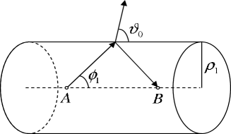
For simplicity let us consider the case when ρ1/ρ0≫1much-greater-thansubscript𝜌1subscript𝜌01\rho_{1}/\rho_{0}\gg 1. In this case for all harmonics the hole radius is much larger than the wavelength of the radiation. We will assume that the particle is relativistic. Obviously, there is a radiation direction Ο•1subscriptitalic-Ο•1\phi_{1} for which the electromagnetic wave radiated at the point A (see figure 6) after the reflection from the wall reaches the point B at the instant of time when the particle is there. That condition is fulfilled if

vβˆ₯=v​cos⁑ϕ0=c​cos⁑ϕ1.subscript𝑣parallel-to𝑣subscriptitalic-Ο•0𝑐subscriptitalic-Ο•1v_{\parallel}=v\cos\phi_{0}=c\cos\phi_{1}. (18)

For certain values of the phase this can lead to the essential change in the radiation intensity. It is clear that the radiation corresponding to the angle Ο•1subscriptitalic-Ο•1\phi_{1} propagates in the exterior medium with the angle (8). As it is seen from figure 1, exactly near Ο‘0subscriptitalic-Ο‘0\vartheta_{0} intense radiation appears. The radiation intensity can be essentially increased if the superposition of the waves at the point B is in the same phase. This is possible if on the optical path 2​ρ12subscript𝜌12\rho_{1} an integer number of waves should be placed:

2​ρ1Ξ›m+Δ​φ2​π=k,2subscript𝜌1subscriptΞ›π‘šΞ”πœ‘2πœ‹π‘˜\frac{2\rho_{1}}{\Lambda_{m}}+\frac{\Delta\varphi}{2\pi}=k, (19)

where Ξ”β€‹Ο†Ξ”πœ‘\Delta\varphi is the phase change in the reflection, Ξ›msubscriptΞ›π‘š\Lambda_{m} is the wavelength in the transverse direction, and k=1,2,β€¦π‘˜12…k=1,2,\ldots. From (19) and data given in figure 2 one can conclude that the change of the phase in the reflection of the wave

Ξ”β€‹Ο†β‰ˆΟ€/2​ at ​ρ1/ρ0≫1.Ξ”πœ‘πœ‹2Β atΒ subscript𝜌1subscript𝜌0much-greater-than1\Delta\varphi\approx\pi/2\text{ at }\rho_{1}/\rho_{0}\gg 1. (20)

By taking into account the relation (18) and formula (4), we have Ξ›m=2​π​c​sin⁑ϕ1/(m​ω0)subscriptΞ›π‘š2πœ‹π‘subscriptitalic-Ο•1π‘šsubscriptπœ”0\Lambda_{m}=2\pi c\sin\phi_{1}/(m\omega_{0}), and for the distance between two neighboring peaks one finds

Δ​(ρ1/ρ0)≃π​tan⁑ϕ1m​tan⁑ϕ0.similar-to-or-equalsΞ”subscript𝜌1subscript𝜌0πœ‹subscriptitalic-Ο•1π‘šsubscriptitalic-Ο•0\Delta(\rho_{1}/\rho_{0})\simeq\frac{\pi\tan\phi_{1}}{m\tan\phi_{0}}. (21)

So the peaks in figures 2, 3 have to be equidistant, which indeed takes place with relative accuracy β‰ˆ0.1%absentpercent0.1\approx 0.1\%.

Now it is obvious from (19), (20) that if a resonance value for ρ1/ρ0subscript𝜌1subscript𝜌0\rho_{1}/\rho_{0} is found for some mπ‘šm, then for the same values of the parameters the amplification of the radiation will be observed for the harmonics mβˆ—=m​(4​l+1)superscriptπ‘šβˆ—π‘š4𝑙1m^{\ast}=m(4l+1), l=0,1,2,…𝑙012…l=0,1,2,\ldots, as well (see figure 4).

Refer to caption
Figure 6: On the explanation of the amplification for the radiation intensity.

As it is seen from formulae (19)-(21), for the problem discussed in section 2 the resonance values for the ratio ρ1/ρ0subscript𝜌1subscript𝜌0\rho_{1}/\rho_{0} do not depend on the dielectric permittivity of the surrounding medium. For this reason, for the same values of ρ1/ρ0subscript𝜌1subscript𝜌0\rho_{1}/\rho_{0} the increase of the radiation intensity has to be observed in the waveguide as well. This is confirmed by the graphs given in figures 3 and 5.

Acknowledgement

The work has been supported by Grant No.Β 1361 from Ministry of Education and Science of the Republic of Armenia.

References

  • [1] V.A.Β Bordovitsyn (Ed.), Synchrotron Radiation Theory and Its Development, World Scientific, Singapore, 1999.
  • [2] A. Hofman, The Physics of Sinchrotron Radiation, Cambridge University Press, Cambridge, 2004.
  • [3] A.A. Saharian, A.S. Kotanjyan, J. Phys. A 38 (2005) 4275.
  • [4] A.A. Saharian, A.S. Kotanjyan, M.L. Grigoryan, J. Phys. A 40 (2007) 1405.
  • [5] L.A. Gevorgian, P.M. Pogosian, Izv. Akad. Nauk Arm. SSR Fiz. 19 (1994) 239.
  • [6] G.G. Karapetyan, Izv. Akad. Nauk Arm. SSR Fiz. 12 (1977) 186.
  • [7] A.S. Kotanjyan, A.A. Saharian, J. Phys. A 40 (2007) 10641.