Coupling of plasmonic nanoparticles to their environments in the context of van der Waals-Casimir interactions
Abstract
We present experiments in which the interaction of a single gold nanoparticle with glass substrates or with another gold particle can be tuned by in-situ control of their separations using scanning probe technology. We record the plasmon resonances of the coupled systems as a function of the polarization of the incident field and the particle position. The distinct spectral changes of the scattered light from the particle pair are in good agreement with the outcome of finite difference time-domain (FDTD) calculations. We believe our experimental technique holds promise for the investigation of the van der Waals-Casimir type interactions between nanoscopic neutral bodies.
pacs:
42.50.-p, 42.50.Lc, 42.25.Fx, 07.79.Fc, 73.22.-fI Introduction
The recent progress in nanotechnology has introduced an immediate need for the optimal design of miniaturized devices and therefore a better understanding and exploitation of the interactions between nanoparticles and surfaces Capasso et al. (2007). In some applications such as mechanical actuation, the main concern is about forces among the nanoscopic components of the system Chan et al. (2001). In some other cases, for example in optical sensing and imaging, the radiation pattern, absorption, emission or scattering spectra of nano-objects are at the center of attention Fritzsche and Taton (2003); Lakowicz (2006). For a number of reasons, metallic nanostructures have played an increasingly important role in these developments. Aside from their electric conductivity, nanoparticles made of noble metals can be chemically and photophysically very stable. Moreover, they provide interesting optical features such as spectral selectivity and the possibility of enhancing optical fields via their plasmon resonances. In this article, we present experimental results on the controlled study of the optical interaction between a single gold nanoparticle and dielectric surfaces as well as the coupling between two individual gold nanoparticles. We discuss our measurements in the context of the van der Waals-Casimir (vdW-C) interactions and point out the potential of our experimental system for investigating the interplay between the classical and quantum mechanical phenomena related to vdW-C interactions.
II A gold nanoparticle as a model dipolar antenna
The scattering properties of nanoparticles can be calculated in terms of multipoles by using the theory developed by G. Mie Mie (1908). If a spherical particle has a diameter that is much smaller than the wavelength of the incident light in the medium surrounding the particle, it can be treated as a dipole with a polarizability Bohren and Huffman (1983)
| (1) |
where and are the dielectric constants of the particle and its surrounding medium respectively, and is the vacuum wavelength. If the material conditions are such that the denominator has a minimum at a certain wavelength, the polarizability and therefore the scattering cross section are enhanced. This can take place for metallic nanoparticles, leading to localized plasmon resonances Bohren and Huffman (1983); Kreibig and Vollmer (1995). The scattering cross section of a subwavelength particle is given by
| (2) |
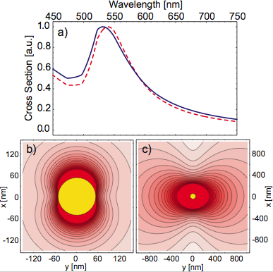
It turns out that a gold nanoparticle placed in air or in a low index dielectric material such as glass shows a resonance in the visible domain (see Fig. 1a). However, plasmon spectra can be varied by changing the size, shape and the dielectric functions of the medium surrounding the particle Bohren and Huffman (1983); Kreibig and Vollmer (1995).
Gold nanospheres of diameter 50 to about 100 nm are in the regime where the dynamical effects become important and the observed plasmon resonance begins to deviate from that predicted by the simple formula in Eq. (1). Nevertheless, it has been shown that the plasmon spectra of such particles can be reproduced very well if one takes into account radiation damping and dynamic depolarization to arrive at an effective dipolar polarizability given by Meier and Wokaun (1983)
| (3) |
Figure 1a shows that the far-field scattering cross section calculated according to Mie theory (blue) agrees quite well with that evaluated by using (dashed red). The contribution of higher multipoles is negligible in the far field, but it could amount to up to 10% of the dipolar one in the near field. This deviation becomes more important for larger particles or higher values of .
It follows that the electric field lines of the light scattered by the nanoparticle trace a dipolar radiation pattern. Figures 1b and c display the strength of the scattered electric field in the near and far fields of the particle, respectively. Thus, gold nanospheres smaller than about 100 nm in diameter can be treated as subwavelength classical dipolar antennae Kalkbrenner et al. (2005); Kühn et al. (2006).
The dipolar character of a gold nanoparticle makes it an ideal approximation to a point-like oscillator, which has been a very useful conceptual construct for relating the classical and quantum mechanical features of an atom Loudon (2000); Haroche (1992). Here, the plasmon resonance plays the roles of the transition between the ground and the excited states. The Rayleigh-like scattering replaces spontaneous emission Mazzei et al. (2007) whereby the particle polarizability and hence its scattering cross section provide a measure for the strength of this process. Furthermore, absorption in a gold particle mimics a nonradiative decay channel in an atom Buchler et al. (2005). Thus, one could expect that optical interactions that influence the spectrum of an atom would have an analog in the context of plasmon resonances of small gold particles.
Of particular interest to the topic of this article is that the plasmon spectrum of a gold nanoparticle can be broadened in a medium of higher dielectric constant Kreibig and Vollmer (1995), similar to the change of the atomic fluorescence decay rate in a dielectric medium Nienhuis and Alkemade (1976). Interestingly, a quick examination of the expression in Eq. (2) shows that as in the case of the Einstein A coefficient, the rate of scattering obtained according to is proportional to and to the square of the dipole moment via . In fact, we recently showed in Ref. Mazzei et al., 2007 that Rayleigh scattering can be also modified if the density of states are manipulated, for example by a high-Q cavity. To this end, one could expect that the plasmon spectrum be modified close to an interface, as was discussed by A. Sommerfeld for a classical dipolar antenna Sommerfeld (1909); Morawitz (1969); Barnes (1998) and by F. London for a quantum mechanical atom London (1930a). In the latter case, the fluctuating quantum mechanical dipole moment of the atomic ground state is assumed to undergo an instantaneous interaction with its image in the nearby mirror. London also showed that the origin of the van der Waals interaction between two atoms is their dipole-dipole interaction London (1930b). Thus, similarly there should be a corresponding van der Waals interaction between a pair of gold nanoparticles.
In this article, we explore such effects by studying the modifications of the plasmon resonances from nanoparticles under controlled conditions. A systematic experimental investigation of the interaction between an oscillating dipole and its surrounding requires a change of its position with an accuracy well beyond where is the dipole oscillation wavelength. This has been explored in atomic physics experimentsSandoghdar et al. (1992); Fichet et al. (1995); Sandoghdar et al. (1996), but neither at the single atom level, nor with nanometer precision. Here we show that both of these issues can be addressed using nanoparticles in the condensed phase.
III Experimental approach
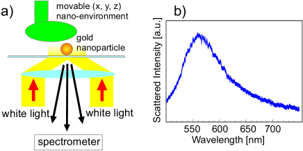
Figure 2a displays the basic setup for recording the plasmon spectrum using an inverted optical microscope. A white light source is used to illuminate the sample in total internal reflection using an immersion oil microscope objective. By proper masking of the incident white light beam Gunnarsson et al. (2005) and using a polarizer, we select a well-defined direction and polarization of illumination. The scattering from the particle is collected by the same microscope objective, passed through a confocal pinhole (not shown) and directed to a spectrometer. Figure 2b shows an experimentally recorded plasmon spectrum of a single gold nanoparticle of diameter 100 nm on a glass substrate.
A home-built scanning near-field optical microscope (SNOM) and a piezo-electric stage are used to move a second object attached to a fiber tip in the immediate vicinity of a gold nanoparticle. The shear-force mechanism Karrai and Tiemann (2000) allows us to control the separation between this object and the gold particle. To do this, the tip is vibrated parallel to the substrate. When the tip comes close to the surface, it experiences a lateral force that dampens its oscillation amplitude. By monitoring this change, the tip can be kept at a constant gap from other objects. Depending on the material of the tip and the substrate, the tip geometry, and the applied oscillation amplitude, the range of the shear-force interaction can be different from a few to a few tens of nanometers Karrai and Tiemann (2000). More details about the setup can be found in Refs. Kalkbrenner et al., 2001, 2005; Buchler et al., 2005
IV The interaction between a gold nanoparticle and two dielectric mirrors
In this section, we examine the interaction of a single gold nanoparticle placed on a glass substrate with a movable glass mirror, as depicted in the inset of Fig. 3. To prepare the sample, we spin coated gold nanoparticles of diameter 100 nm (British Biocell International) on a glass cover slide with a dilute coverage of the order of one particle per . The incident light could be adjusted to have a or polarization. A pinhole is placed in the detection path in order to reduce the background scattering and collect the signal from a very small region of the order of one micrometer. For the movable mirror, we used a microsphere of diameter melted at the end of an optical fiberBuchler et al. (2005). The fiber was mounted in the SNOM stage so that the microsphere surface could be approached to the gold nanoparticle with nanometer precision. Given that we investigate very small separations of the order of one micrometer, in what follows we approximate this slightly curved surface by a flat mirror.
Determining a shift or broadening of the plasmon resonance can be a subtle task because the plasmon resonance is not symmetric and does not possess a simple line profile. To assign the resonance peak, we fitted each plasmon spectrum by using the dipolar approximation and an effective polarizability of Eq. (3), as described in Ref. Buchler et al., 2005. Alternatively, we used the procedure in Ref. Kuwata et al., 2003. Using both methods, we could determine the peak of the resonance with a resolution of about 0.5 nm. Next, by comparing the plasmon spectrum recorded in the presence of the movable curved glass surface with that in its absence, a spectral shift was extracted for each position. The symbols in Fig. 3 show the shift of the plasmon resonance recorded at different surface-surface separations for p-polarized illumination. We see clearly that the plasmon resonance experiences a red shift with a steep gradient at close distances. This can be understood as the attractive near-field interaction of the plasmon oscillation and its instantaneous mirror image in the nearby surface. Such an energy shift has been previously reported for ensembles of metallic nanostructure Holland and Hall (1984); Murray et al. (2006), but to our knowledge this is the first report on the spectral shift of single particles.
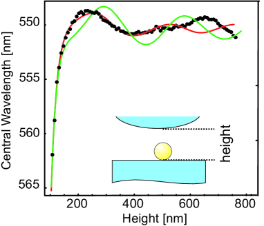
At larger separations, Fig. 3 reveals oscillations, again as expected from the theoretical work on the interaction between a classical dipole and a mirror Chance et al. (1978); Hinds and Sandoghdar (1991). These oscillations have also been reported recently for ensembles of metallic nanostructures Murray et al. (2006), but their analysis requires a great deal of care. The oscillations seem to be irregular and deviate from the theoretical values (green curve) obtained by considering the frequency shift of a classical dipole placed between two flat glass surfaces Sullivan and Hall (1997). In these calculations a point-like dipole was fixed at a distance of 50 nm (the radius of the gold nanoparticle) from a glass substrate and a second glass surface was scanned. We believe the cause of these deviations is a subtle interference effect between the light scattered by the particle and other objects (e.g. the substrate) in its vicinity. In the particular case of the current experiment, the evanescent illumination can be scattered by the gold particle and subsequently reflected back into the detection path by the second curved surface in the vicinity. Since in these experiments the separations between the objects under consideration are very small, the background scattering is coherent with the light that is scattered from the nanoparticle of interest. It turns out that despite the use of a pinhole in detection, some of the background scattering reaches the detector and interferes with the field from the particle. As distances are changed, this interference gives rise to wavelength-dependent intensity modulations and skews the broad plasmon resonance by a small amount, thus causing a systematic error in the extracted resonance wavelength peak values. We have verified that this effect is stronger for the s-polarized illumination because this light is more efficiently scattered along the axis of the microscope objective. A detailed account of this effect can be found in the supplementary materials of Ref. Kalkbrenner et al., 2005. Our efforts to fully eliminate this systematic effect have not been successful so far. However, this phenomenon can be crudely taken into account in the fit to the experimental data by allowing for a small sinusoidal function added to the theoretically calculated values. The outcome of such a fit is shown by the red curve in Fig. 3. The fact that the correction is no longer effective for larger distances might indicate that the background scattering stems from more than one point. We emphasize, however, that this systematic problem is not of concern for near-field measurements.
We note that the point-dipole model breaks down when a nanoparticle is closer than about a particle diameter. Nevertheless, the orders of magnitude and the general trend of the calculated modification of the plasmon resonance seems to yield a good agreement with the experimental results discussed above and in Refs. Kalkbrenner et al., 2005; Buchler et al., 2005. In the next section, we discuss the interaction between two nanoparticles and compare our experimental data with the outcome of numerical simulations.
V The interaction of two gold nanoparticles
In order to investigate the coupling of two gold nanoparticles in a well-defined manner, we have exploited scanning probe technology to control their relative positions in-situ. One gold particle () is attached to the end of a glass fiber tip, following the preparation technique that we have reported previously Kalkbrenner et al. (2001, 2004). The second particle () is selected from a very low concentration of nanoparticles (diameter of 100 nm) spin coated on a glass substrate. The plasmon resonances of each particle can be recorded separately in the configuration shown in Fig. 2a.
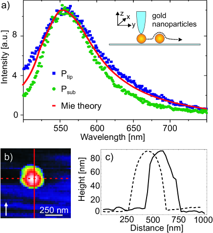
The blue and green symbols in Fig. 4a show the plasmon spectra of and recorded independently, under s-polarized incident light. The two particles were chosen to have very similar plasmon spectra. Furthermore, by examining these spectra as a function of the polarization of the excitation light, we verified that they were spherical Kalkbrenner et al. (2004). The red trace in Fig. 4a represents a calculated Mie spectrum for a 100 nm spherical particle using the tabulated dielectric function of gold Johnson and Christy (1972). In order to obtain the best agreement with the spectra of both and , an effective refractive index of for the surrounding medium was taken. Here, one has to bear in mind that the immediate environments of and (i.e. a glass tip and a glass substrate) are asymmetric, so that it is a nontrivial matter to define a dielectric function for the medium surrounding the nanoparticles. Nevertheless, it has been previously shown that a weighted average of the dielectric constants of the various surrounding media yields reasonably good agreement with experimental data Tamaru et al. (2002); Hilger et al. (2001). In what follows, the red curve in Fig. 4a will be used as the basis for the theoretical modelling of the particle-particle interaction.
After determining the optical properties of the two particles individually, we set out to study the interaction between them. The drawing in Fig. 4a shows the schematics of the experimental arrangement. Using the SNOM stage, we can position both the tip and the sample with nanometer accuracy. Furthermore, shear force tip-sample distance control allows for combined topographic and optical studies. Figure 4b shows the measured topography of as was scanned across it, and Fig. 4c displays the cross sections corresponding to the two cuts parallel and perpendicular to the polarization of the illumination. At each scan pixel of 25 nm, we trigger the spectrometer and record the scattering spectra of the two gold nanoparticles. Figures 5a and b show selections of spectra from the first halves of the scans marked by cross sections shown in Fig. 4b. In an intuitive picture where each particle acts as an induced electric dipole moment directed along the incident field polarization, these two series explore the dipole-dipole interaction for the head-to-tail and side-by-side configurations, respectively Quinten (1998); Rechberger et al. (2003); Dahmen et al. (2007).
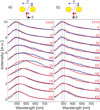
Let us first concentrate on the case of Fig. 5a. As the two particles are brought closer from the large separation of nm, the pair spectrum becomes broader and is shifted to the longer weavelength. Here the parameter denotes the projection of the center-to-center particle separation onto the substrate. This was extracted from the topographic information recorded simultaneously to the optical spectra, taking into account a vertical offset of 15 nm due to the shear force interaction length between tip and substrate Karrai and Tiemann (2000). At nm the spectral shift amounts to a maximum of about nm. As the tip is scanned further in shear-force control, is lifted upward, resulting in a narrower and blue-shifted spectrum. When is above (i.e. ), the spectrum has become even narrower than the starting point, and its center wavelength is shifted to a lower wavelength by about 15 nm.
To compare our findings with theoretical expectations, we have performed Finite-Difference Time-Domain (FD-TD) calculations of the total scattering cross section of two spherical particles with diameters of 100 nm Taflove and Hagness (2005); Oubre and Nordlander (2004). We treat the dielectric function of gold using a Drude-Lorentz model Vial et al. (2005). The space discretization has a step size of nm, which has been shown to be small enough to obtain results with accuracy. Oubre and Nordlander (2004) To ensure that the scattered light exits the computational volume without reflections, we used Convolutional-Perfectly-Matched-Layers (CPML) absorbing boundary conditions Roden and Gedney (2000). The calculations took into account the experimentally measured trajectory of the moving particle extracted from the topography information (see Fig. 4). For positions where the tip is lifted from the substrate, the effective refractive index of the surrounding media had to be reduced to (corresponding to a decrease) in order to obtain a good agreement with the experimental results. We note that consideration of an effective index for the glass-air interface is common also when using fully analytical Mie theory Kreibig and Vollmer (1995).
The agreement between the measured and the calculated spectra in Fig. 5a are generally very good aside from the region about nm. At such small separations the plasmon resonance is very sensitive to the exact distance between the particles. To display this sensitivity to position, in Fig. 6 we compare the experimental spectra for nm with five calculated plasmon spectra in which is varied between nm and nm. We see that changing the particle distance by merely nm shifts the peak of the plasmon spectrum more than nm. Indeed, it is this sensitivity to displacements that constitutes the core idea of the recently proposed “plasmon rulers.” Sönnichsen et al. (2005); Reinhard et al. (2005) During the analysis of these results, we have realized that the tip oscillations (see section III) were excited too strongly in these experiments. We have verified this hypothesis by a direct measurement of the tip oscillation amplitude under the same experimental conditions.
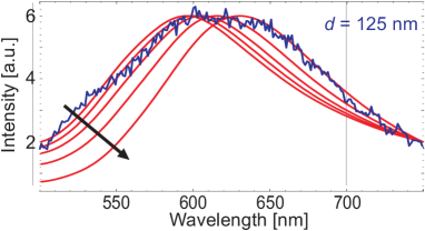
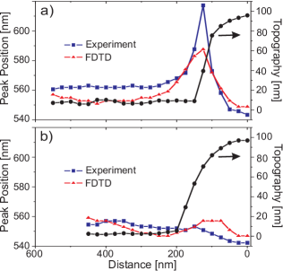
Figure 7a summarizes our results from the configuration depicted in Fig. 5a. The experimental (blue) and theoretical (red) peak wavelengths are plotted as a function of the tip position together with the corresponding topography cross section. For large , and lie along the incident electric field. As is decreased, we observe a shift of the resonance to the longer wavelengths, corresponding to an attractive interaction expected for the induced particle dipoles in a head-to-tail orientation. This red shift is also accompanied by a broadening, which can be attributed to a stronger radiative decay of the coupled system. Although the system of two 100 nm particles no longer behaves as a pure dipolar radiator, the simple picture of two dipoles adding up to yield one larger dipole provides the correct intuition. As mounts , the dipole arrangement quickly changes to a side-by-side configuration, and the interaction becomes strongly repulsive. For , the plasmon resonance of the coupled system is blue shifted by about 15 nm with respect to the non-interacting spectra. All these trends are recovered by the FDTD calculations. Moreover, the theoretical results predict a very small blue shift of the spectrum in the region due to oscillation that stem from the retarded interaction energy between two dipoles Dahmen et al. (2007). Our experimental data do not show this behavior. However, here one has to remember that the small deviations between the plasmon resonances of the individual particles (see Fig. 4a) are not negligible at this level of comparison between theory and experiment.
The situation for the configuration of Fig. 5b is presented in Fig. 7b and is quite different. In comparison to the case of Fig. 7a, the interaction is weaker. Here the polarization is perpendicular to the axis joining the particles so that the relative orientation of the dipoles in the two nanoparticles does not change during the entire scan. As the particles approach each other, there is a shift towards lower wavelengths, signifying a repulsive force. Again, the theoretical calculations show the same trend. The difference between the measured and theoretical peak positions at small distances stems from a lack of perfect agreement between the recorded and calculated lineshapes shown in Fig. 5b.
Next, we remark on the widths of the plasmon resonances. Again, aside from the separations around nm, the agreement between the experimental and the FDTD results are quite good. We find that in Fig. 5a the attractive coupling between the two particles is always accompanied by a spectral broadening. An intuitive interpretation of this result is that at close distances the head-to-tail arrangement gives rise to a total dipole moment that is larger than that of each particle. As a result, the system can radiate more strongly. The strong fields between the particles in this arrangement are also responsible for the large enhancements obtained in surface enhanced spectroscopy. Moskovits (1985) Nevertheless, we emphasize that the simple picture of dipole-dipole coupling breaks down when the particles are very close to each other, and the contribution of multipoles should be taken into account Nordlander et al. (2004).
By changing the interparticle distance and the orientation of the pair relative to the polarization of the excitation, the plasmon spectrum of the coupled system has been tuned by about 70 nm. On the one hand, this shows the feasibility of the recent proposal for using the distance dependent modification of plasmon resonances as a measure for separation Sönnichsen et al. (2005). On the other hand, the data in Figs. 5 and 7 emphasize that great care must be taken when extracting distance information because changes of the polarization in relation to the particle pair axis has a dramatic effect on the interaction. Moreover, variations in the dielectric functions of the immediate surrounding could strongly affect the scattering spectra. Kalkbrenner et al. (2005)
VI Discussion
Modification of plasmon resonances of close lying particles have been studied previously using various approaches. Most commonly, researchers have examined ensembles of particles that have been nanofabricated or chemically produced Rechberger et al. (2003); Su et al. (2003); Atay et al. (2004); Tamaru et al. (2002); Wei et al. (2004); Gunnarsson et al. (2005); Sundaramurthy et al. (2005). To remedy the inevitable inhomogeneities of prefabricated systems, optical trapping of a single pair of silver particlesPrikulis et al. (2004) and directed assembly of silver and gold dimersSönnichsen et al. (2005) have been also attempted. Our experimental approach has the great advantage that a single nanoparticle can be positioned with nanometer accuracy. In addition, our system allows one to explore the analogy between the modifications of plasmon resonances and vdW-C interactions.
Shortly after London’s quantum mechanical description of the van der Waals interactions London (1930b, a), Casimir and Polder showed that a treatment based on quantized electromagnetic fields introduces corrections to the London model Casimir and Polder (1948). In the case of an atom in front of a mirror, the vacuum field experiences boundary conditions and the local density of states are altered, leading to the modification of the energy levels and of the atomic fluorescence lifetime. The functional forms of the vdW-C interactions turn out to be different for the ground and excited states. At short atom-surface distances , the interaction between the atom and the surface can be considered as quasi-instantaneous so that both the ground and the excited states experience a decrease in energy. At larger distances, retardation takes effect and the ground state energy drops as whereas the excited state undergoes oscillatory changes in the energy and decay rate Drexhage (1974); Haroche (1992); Hinds and Sandoghdar (1991); Barnes (1998). A similar situation takes place if the interaction between two atoms is considered Casimir and Polder (1948). In a physical picture, the atoms are polarized by the fluctuating vacuum fields at all possible frequencies, k-vectors and polarizations. When the separations are much smaller than a transition wavelength, the induced dipole moments in the atoms are quasi-instantaneous so that their interaction can be treated as an electrostatic dipole-dipole coupling, yielding a interaction energy London (1930b). For atoms placed at large separations, the finite speed of light leads to an effective dephasing of the dipole moments, changing the distance dependence of the energy from to . The above-mentioned interactions establish the fundament of the forces between neutral bodies.
Interestingly, many of the features of the vdW-C interactions of excited atoms can be described by considering an atom as a “point-like” classical dipolar antenna that interacts with its own radiated field after reflection from the boundaries Chance et al. (1978). However, the classical picture does not match the quantum electrodynamic calculations fully. For example, it has been shown that the excited state energy of the atom cannot be described by a classical dipole near and far from the mirror simultaneously Meschede et al. (1990); Hinds and Sandoghdar (1991). This observation and the fact that the stability and energy shift of the ground state cannot be described by classical models have raised many interesting discussions regarding the role of quantum electrodynamics in the interaction of neutral bodies Milonni (1994). It would be thus intriguing to realize systems where the similarities and differences between a classical point-like dipole and a quantum mechanical atom can be studied experimentally.
Subwavelength gold nanoparticles might provide a promising system for this purpose. On the one hand, such particles (diameter larger than about 10 nm) are much larger than single atoms so that one can use the dielectric function of bulk gold and classical electromagnetic methods to describe their optical properties. In this regard, they can be seen as the miniaturized versions of neutral bodies that have been commonly used for studying vdW-C forces Lamoreaux (1997); Mohideen and Roy (1998); Roy and Mohideen (1999). On the other hand, they can be considered to be point-like since they are much smaller than a wavelength. The plasmon resonance of a gold nanoparticle lets it act as a classical dipolar antenna whose radiation behaves like that of an atomic excited state. At the same time, a nanoparticle is similar to the ground state of a quantum mechanical atom in the sense that it does not emit light and is radiatively stable.
Modification of the plasmon spectra of gold nanoparticles in the near field of an interface has been verified experimentally Holland and Hall (1984); Buchler et al. (2005); Kalkbrenner et al. (2005); Murray et al. (2006) and has been described using classical models. Recently a few publications have viewed such interactions in the light of vdW-Casimir forces Ford (1998); Noguez and Roman-Velazquez (2004); Noguez et al. (2004). Although the plasmon spectra can be determined by solving classical Maxwell equations, one can formulate these interactions also in the common language of cavity quantum electrodynamics. In this picture, the vacuum field excites plasmon oscillations in the gold nanoparticle much as in the case of a ground state atom. If external boundary conditions are present, the density of states are modified, leading to the change of the plasmon spectrum. A similar point of view has been also discussed regarding the role of the surface plasmons in the attraction of metallic mirrors Intravaia and Lambrecht (2005). Thus, by comparing the near- and far-field modifications of the plasmon spectra and by treating the plasmon oscillations quantum mechanically, one might be able to bridge the quantum world of atoms and the classical realm of dipolar antennae.
Although it might be tempting to establish a direct link between the plasmon resonance shifts summarized in Fig. 7 and the vdW-C interaction energies for the coupled particle system, one has to remember that our measurements have recorded spectra for particular directions of illumination and polarizations. However, calculations of the vdW-C interaction energy should take into account contributions of vacuum fluctuations at all wavelengths, polarizations and k-vectors. Nevertheless, given that the “response” of the system is the same for excitations by virtual and real photons, it might be possible to extrapolate the laboratory measurements to infer the vdW-C interaction energy. Such theoretical considerations go beyond the scope of our current work, but very recent advances in calculation of Casimir forces Emig et al. (2007) might be able to investigate such matters.
It is also instructive to consider the orders of magnitudes of the forces involved. The largest measured gradient of the energy-distance curves in Fig. 7a amounts to which corresponds to a force of pN. We estimate the smallest force that is detectable with our signal-to-noise ratio to be a few tens of fN, which is nearly two orders of magnitude smaller than the sensitivity of the recent force experiments Mohideen and Roy (1998); Chan et al. (2001). Investigation of the vdW-C interactions of metallic nanoparticles via spectroscopy could have several advantages over direct force measurements. In particular, one would be less sensitive to residual effects such as electrostatic forces. Moreover, the optical constants of the particles under study could be measured in-situ Stoller et al. (2006).
From an experimental point of view, the controlled laboratory measurements of the vdW-C interactions and comparisons with theory remain not only challenging for atoms and macroscopic objects, but also for nanoparticles. First, the interactions are weak except at very small separations. Second, they are strongly distance dependent so that nanometer distance control is required. Third, the geometrical and material features of the objects play an important role and are not always well defined. In order to address these experimental issues and realize a well-defined and controllable system, we have followed a simple strategy to place a single nanoparticle at the end of a sharp glass fiber tip and have used scanning probe technology to place it in nanoscopic confined geometries Kalkbrenner et al. (2001); Buchler et al. (2005); Kalkbrenner et al. (2005); Kühn et al. (2006). This approach has been very fruitful and has been also pursued by other groups Eah et al. (2005); Anger et al. (2006); Danckwerts and Novotny (2007) for performing controlled measurements with individual nanoparticles.
VII Conclusion
We have studied the weak interaction between a well characterized single nanoparticle and a macroscopic dielectric mirror or a second gold nanoparticle. Both red and blue shifts of the plasmon spectrum as well as its broadening and narrowing were observed. Several aspects of these experiments were not ideal and could be improved for more precise measurements. In the first experiment, residual reflections that can interfere with the light scattered by the particles should be minimized Kalkbrenner et al. (2005). In the latter experiment, more care should be given to maintaining a minimal oscillation of the tip to avoid broadening of the spectra. It would be particularly interesting to perform this experiment in immersion oil to eliminate the influence of the glass substrate and the tip.
We have discussed our measurements in the context of the van der Waals-Casimir interactions between neutral bodies. Both theoretical and experimental reports in the literature have typically considered two extreme cases of vdW-C interactions where the objects are either single atoms and molecules or they are macroscopic bodies with dimensions larger than a few micrometers. Scanning probe manipulation and spectroscopy of very small gold nanoparticles could allow access to an intermediate regime. Mounting a nanoparticle at the end of an AFM tip would also provide the possibility of simultaneously measuring the force and spectral modifications. In particular, such spectroscopic studies could be easily extended to metallic particles of the order of 5 nm in diameter Lindfors et al. (2004); Stoller et al. (2006), which bridge the quantum mechanical and classical regimes.
Finally, our experiments could be considered as the in-situ realization of a tunable optical nanoantenna Greffet (2005); Mühlschlegel et al. (2005). We have recently shown that a pair of gold nanoparticles can act as a very efficient antenna system for enhancing the spontaneous emission of an emitter placed in their gap Rogobete et al. (2007). Given that the performance of such devices requires an extremely high accuracy in the relative coordinates and orientation of both the emitter and the nanoparticles, a tunable setup Kühn et al. (2006) will be of great advantage.
References
- Capasso et al. (2007) F. Capasso, J. N. Munday, D. Iannuzzi, and H. B. Chan, IEEE J. Sel. Top. Quant. Elect. 13, 400 (2007).
- Chan et al. (2001) H. B. Chan, V. A. Aksyuk, R. N. Kleiman, D. J. Bishop, and F. Capasso, Science 291, 1941 (2001).
- Fritzsche and Taton (2003) W. Fritzsche and T. A. Taton, Nanotechnology 14, R63 (2003).
- Lakowicz (2006) J. R. Lakowicz, Plasmonics 1, 5 (2006).
- Mie (1908) G. Mie, Ann. Phys. 25, 378 (1908).
- Bohren and Huffman (1983) C. F. Bohren and D. R. Huffman, Absorption and Scattering of Light by Small Particles (John Wiley and Sons, 1983).
- Kreibig and Vollmer (1995) U. Kreibig and M. Vollmer, Optical Properties of Metal Clusters (Springer Berlin, 1995).
- Meier and Wokaun (1983) M. Meier and A. Wokaun, Opt. Lett. 8, 581 (1983).
- Kalkbrenner et al. (2005) T. Kalkbrenner, U. Håkanson, A. Schädle, S. Burger, C. Henkel, and V. Sandoghdar, Phys. Rev. Lett. 95, 200801 (2005).
- Kühn et al. (2006) S. Kühn, U. Håkanson, L. Rogobete, and V. Sandoghdar, Phys. Rev. Lett. 97, 017402 (2006).
- Loudon (2000) R. Loudon, Quantum Theory of Light (Oxford University Press, 2000).
- Haroche (1992) S. Haroche, Fundamental systems in quantum optics (North-Holland, Amsterdam, 1992), chap. Cavity quantum electrodynamics, pp. 767–940.
- Mazzei et al. (2007) A. Mazzei, S. Götzinger, L. de S. Menezes, O. Benson, and V. Sandoghdar, Phys. Rev. Lett. 99, 173603 (2007).
- Buchler et al. (2005) B. C. Buchler, T. Kalkbrenner, C. Hettich, and V. Sandoghdar, Phys. Rev. Lett. 95, 063003 (2005).
- Nienhuis and Alkemade (1976) G. Nienhuis and C. T. J. Alkemade, Physica 81C, 181 (1976).
- Sommerfeld (1909) A. Sommerfeld, Ann. Phys. 28, 665 (1909).
- Morawitz (1969) H. Morawitz, Phys. Rev. 187, 1792 (1969).
- Barnes (1998) W. L. Barnes, J. Mod. Optic 45, 661 (1998).
- London (1930a) F. London, Z. Phys. Chem. B 11, 222 (1930a).
- London (1930b) F. London, Z. Physik 63, 245 (1930b).
- Sandoghdar et al. (1992) V. Sandoghdar, C. Sukenik, E. A. Hinds, and S. Haroche, Phys. Rev. Lett. 68, 3432 (1992).
- Fichet et al. (1995) M. Fichet, F. Schuller, D. Bloch, and M. Ducloy, Phys. Rev. A 51, 1553 (1995).
- Sandoghdar et al. (1996) V. Sandoghdar, C. I. Sukenik, E. A. Hinds, and S. Harcohe, Phys. Rev. A. 53, 1919 (1996).
- Gunnarsson et al. (2005) L. Gunnarsson, T. Rindzevicius, J. Prikulis, B. Kasemo, M. Käll, S. Zou, and G. C. Schatz, J. Phys. Chem. B 109, 1079 (2005).
- Karrai and Tiemann (2000) K. Karrai and I. Tiemann, Phys. Rev. B 62, 13174 (2000).
- Kalkbrenner et al. (2001) T. Kalkbrenner, M. Ramstein, J. Mlynek, and V. Sandoghdar, J. Micros. 202, 72 (2001).
- Kuwata et al. (2003) H. Kuwata, H. Tamara, K. Esumi, and K. Miyano, Appl. Phys. Lett. 83, 4625 (2003).
- Holland and Hall (1984) W. R. Holland and D. G. Hall, Phys. Rev. Lett. 52, 1041 (1984).
- Murray et al. (2006) W. A. Murray, J. R. Suckling, and W. L. Barnes, Nano Lett. 6, 1772 (2006).
- Chance et al. (1978) R. R. Chance, A. Prock, and R. Silbey, Adv. Chem. Phys. 37, 1 (1978).
- Hinds and Sandoghdar (1991) E. A. Hinds and V. Sandoghdar, Phys. Rev. A 43, 398 (1991).
- Sullivan and Hall (1997) K. G. Sullivan and D. G. Hall, J. Opt. Soc. Am. B 14, 1149 (1997).
- Kalkbrenner et al. (2004) T. Kalkbrenner, U. Håkanson, and V. Sandoghdar, Nano Lett. 4, 2309 (2004).
- Johnson and Christy (1972) P. B. Johnson and R. W. Christy, Phys. Rev. B 6, 4370 (1972).
- Tamaru et al. (2002) H. Tamaru, H. Kuwata, H. T. Miyazaki, and K. Miyano, Appl. Phys. Lett. 80, 1826 (2002).
- Hilger et al. (2001) A. Hilger, M. Tenfelde, and U. Kreibig, Appl. Phys. B 73, 361 (2001).
- Quinten (1998) M. Quinten, Appl. Phys. B 67, 101 (1998).
- Rechberger et al. (2003) W. Rechberger, A. Hohenau, A. Leitner, J. R. Krenn, B. Lamprecht, and F. R. Aussenegg, Opt Comm. 220, 137 (2003).
- Dahmen et al. (2007) C. Dahmen, B. Schmidt, and G. von Plessen, Nano Lett. 7, 318 (2007).
- Taflove and Hagness (2005) A. Taflove and S. C. Hagness, Computational Electrodynamics: the Finite-Difference Time-Domain Method. – 3rd ed. (Artech House, Norwood, MA, 2005).
- Oubre and Nordlander (2004) C. Oubre and P. Nordlander, J. Phys. Chem. B 108, 17740 (2004).
- Vial et al. (2005) A. Vial, A.-S. Grimault, D. Macías, D. Barchiesi, and M. L. de la Chapelle, Phys. Rev. B 71, 085416 (2005).
- Roden and Gedney (2000) J. Roden and S. Gedney, Microw. Opt. Technol. Lett. 27, 334 (2000).
- Sönnichsen et al. (2005) C. Sönnichsen, B. Reinhard, J. Liphardt, and A. P. Alivisatos, Nature Bio. Tech. 23, 741 (2005).
- Reinhard et al. (2005) B. M. Reinhard, M. Siu, H. Agarwal, A. P. Alivisatos, and J. Liphardt, Nano Lett. 5, 2246 (2005).
- Moskovits (1985) M. Moskovits, Rev. Mod. Phys. 57, 783 (1985).
- Nordlander et al. (2004) P. Nordlander, C. Oubre, E. Prodan, K. Li, and M. I. Stockman, Nano Lett. 4, 899 (2004).
- Su et al. (2003) K.-H. Su, Q.-H. Wei, X. Zhang, J. J. Mock, D. R. Smith, and S. Schultz, Nano Lett. 3, 1087 (2003).
- Atay et al. (2004) T. Atay, J.-H. Song, and A. V. Nurmikko, Nano Lett. 4, 1627 (2004).
- Wei et al. (2004) Q.-H. Wei, K.-H. Su, S. Durant, and X. Zhang, Nano Lett. 4, 1067 (2004).
- Sundaramurthy et al. (2005) A. Sundaramurthy, K. B. Crozier, G. S. Kino, D. P. Fromm, P. J. Schuck, and W. E. Moerner, Phys. Rev. B 72, 165409 (2005).
- Prikulis et al. (2004) J. Prikulis, F. Svedberg, M. Käll, J. Enger, K. Ramser, M. Goksör, and D. Hanstorp, Nano Lett. 4, 115 (2004).
- Casimir and Polder (1948) H. B. G. Casimir and D. Polder, Phys. Rev. 73, 360 (1948).
- Drexhage (1974) K. H. Drexhage, Progress in Optics 12, 165 (1974).
- Meschede et al. (1990) D. Meschede, W. Jhe, and E. A. Hinds, Phys. Rev. A 41, 1587 (1990).
- Milonni (1994) P. W. Milonni, The Quantum Vacuum (Academic Press, New York, 1994).
- Lamoreaux (1997) S. K. Lamoreaux, Phys. Rev. Lett. 78, 5 (1997).
- Mohideen and Roy (1998) U. Mohideen and A. Roy, Phys. Rev. Lett. 81, 4549 (1998).
- Roy and Mohideen (1999) A. Roy and U. Mohideen, Phys. Rev. Lett. 82, 4380 (1999).
- Ford (1998) L. H. Ford, Phys. Rev. A 58, 4279 (1998).
- Noguez and Roman-Velazquez (2004) C. Noguez and C. E. Roman-Velazquez, Phys. Rev. B 70, 195412 (2004).
- Noguez et al. (2004) C. Noguez, C. E. Roman-Velazquez, R. Esquivel-Sirvent, and Villarreal, Europhys. Lett. 67, 191 (2004).
- Intravaia and Lambrecht (2005) F. Intravaia and A. Lambrecht, Phys. Rev. Lett. 94, 110404 (2005).
- Emig et al. (2007) T. Emig, N. Graham, R. L. Jaffe, and M. Kardar, Phys. Rev. Lett. 99, 170403 (2007).
- Stoller et al. (2006) P. Stoller, V. Jacobsen, and V. Sandoghdar, Opt. Lett. 31, 2474 (2006).
- Eah et al. (2005) S.-K. Eah, H. M. Jaeger, N. F. Scherer, G. P. Wiederrecht, and X.-M. Lin, Appl. Phys. Lett. 86, 031902 (2005).
- Anger et al. (2006) P. Anger, P. Bharadwaj, and L. Novotny, Phys. Rev. Lett. 96, 113002 (2006).
- Danckwerts and Novotny (2007) M. Danckwerts and L. Novotny, Phys. Rev. Lett. 98, 026104 (2007).
- Lindfors et al. (2004) K. Lindfors, T. Kalkbrenner, P. Stoller, and V. Sandoghdar, Phys. Rev. Lett. 93, 037401 (2004).
- Greffet (2005) J.-J. Greffet, Science 308, 1561 (2005).
- Mühlschlegel et al. (2005) P. Mühlschlegel, H.-J. Eisler, O. Martin, B. Hecht, and D. Pohl, Science 308, 1607 (2005).
- Rogobete et al. (2007) L. Rogobete, F. Kaminski, M. Agio, and V. Sandoghdar, Opt. Lett. 32, 1623 (2007).