Three-dimensional dielectric photonic crystal structures for laser-driven acceleration
Abstract
We present the design and simulation of a three-dimensional photonic crystal waveguide for linear laser-driven acceleration in vacuum. The structure confines a synchronous speed-of-light accelerating mode in both transverse dimensions. We report the properties of this mode, including sustainable gradient and optical-to-beam efficiency. We present a novel method for confining a particle beam using optical fields as focusing elements. This technique, combined with careful structure design, is shown to have a large dynamic aperture and minimal emittance growth, even over millions of optical wavelengths.
Submitted to Physical Review Special Topics – Accelerators and Beams
pacs:
41.75.Jv, 42.70.QsI Introduction
The extraordinary electric fields available from laser systems make laser-driven charged particle acceleration an exciting possibility. Because of the maturity of RF accelerator technology, it is tempting to try to scale down traditional microwave accelerators to optical wavelengths. However, this proposal encounters several obstacles in the structure design. First, because of the significant loss of metals at optical frequencies, we wish instead to use dielectric materials for a structure. Second, manufacturing a circular disk-loaded waveguide on such small scales poses a significant challenge. For these reasons, we must consider structures which differ significantly from those used in conventional accelerators.
So far, macroscopic, far-field structures have been investigated experimentally as a means to exploit high laser intensities for linear particle acceleration. In the Laser Electron Acceleration Program (LEAP), a free-space mode was used to modulate an unbunched electron beam Plettner et al. (2005). The experiment demonstrated the expected linear scaling of energy modulation with laser electric field as well as the expected polarization dependence. The next stage of the experimental program, to be performed at the E163 facility at SLAC, seeks to demonstrate net energy gain by first optically bunching the electron beam using an IFEL Barnes et al. (2002); Sears et al. (2007). Beyond that, the desire is to demonstrate a scalable acceleration mechanism. For that purpose, a near-field, guided-mode structure would be more suitable.
Photonic crystals Joannopoulos et al. (1995) provide a means of guiding a speed-of-light optical mode in an all-dielectric structure. They have been investigated for some time for metallic RF accelerator structures because of their potential for eliminating a major source of beam break-up instability Li et al. (1997); Kroll et al. (1999). In the optical regime, a synchronous mode has been shown to exist in a photonic crystal fiber Lin (2001). Several years ago a study was conducted of two-dimensional planar structures Cowan (2003). While the study was informative, such two-dimensional planar structures are ultimately impractical because they only confine the accelerating mode in one transverse direction. In this paper we present a three-dimensional structure which overcomes this deficiency, confining the mode in both transverse dimensions.
In Sec. II we present the structure geometry and accelerating mode. Then in Sec. III we analyze the performance of the structure in terms of accelerating gradient and optical-to-beam efficiency. In Sec. IV we address single-particle beam dynamics in the structure, presenting a focusing-defocusing lattice and demonstrating stable beam propagation.
II Structure geometry and accelerating mode
The accelerator structure is based on the so-called “woodpile” geometry, a well-established three-dimensional photonic crystal lattice designed to provide a complete photonic bandgap in a structure with a straightforward fabrication process Ho et al. (1994). The lattice consists of layers of dielectric rods in vacuum, with the rods in each layer rotated 90° relative to the layer below and offset half a lattice period from the layer two below, as shown with the coordinate system in Fig. 1.
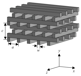
We consider laser acceleration using a wavelength of 1550 nm, in the telecommunications band where many promising sources exist IMR . At this wavelength silicon has a normalized permittivity of Edwards (1985). We let be the horizontal lattice constant, and take . As described in Ho et al. (1994) the lattice has a face-centered cubic structure and exhibits an omnidirectional bandgap. Based on those results, we take the rod width to be . The ratio of the width of the bandgap to its center frequency is 18.7%.
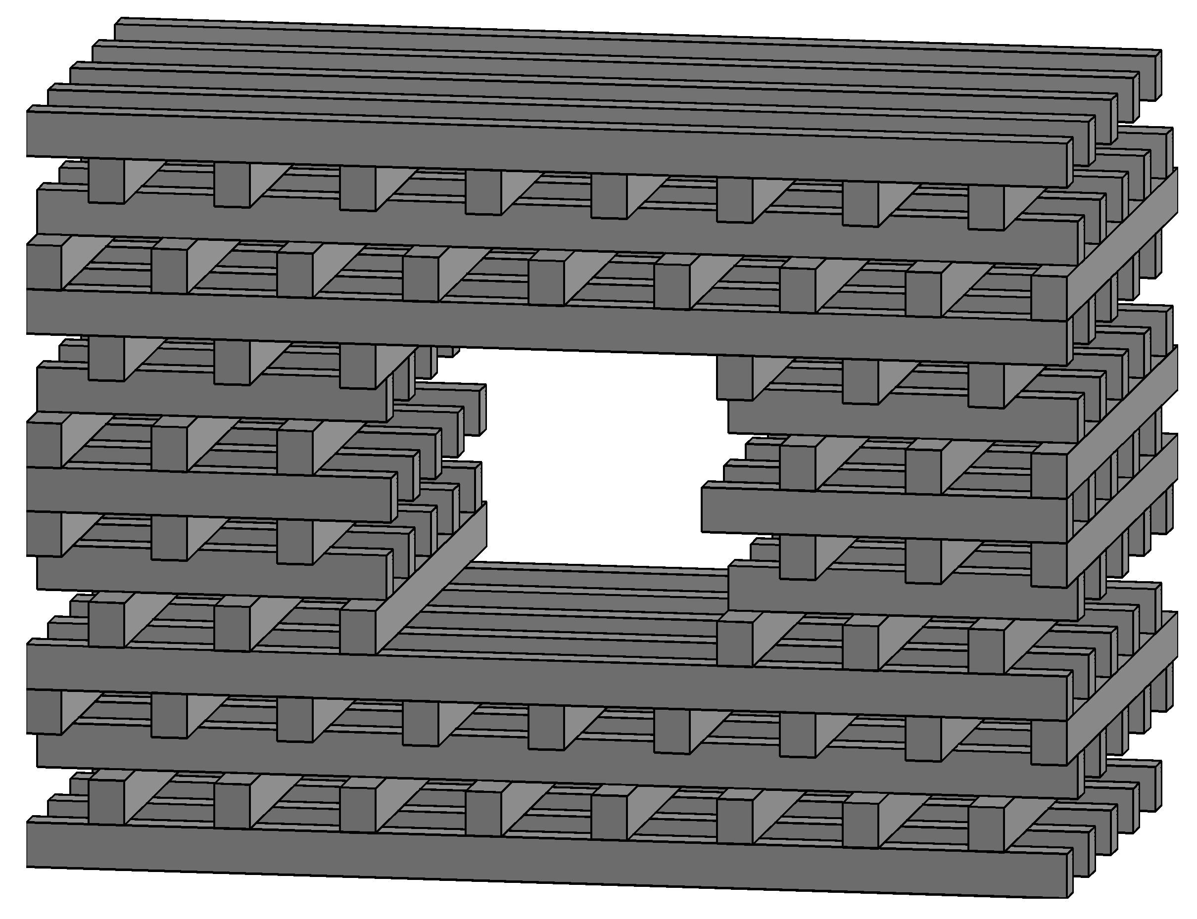
We form a waveguide by removing all dielectric material in a region which is rectangular in the transverse and dimensions, and extends infinitely in the -beam propagation direction . In addition, there are two modifications: In order to avoid deflecting fields in the accelerating mode, we make the structure vertically symmetric by inverting the upper half of the lattice so it is a vertical reflection of the lower half. Second, we extend the central bars into the waveguide by on each side in order to suppress quadrupole fields. The consequences of this perturbation will be discussed further in Sec. IV. The geometry, with a defect waveguide introduced, is shown schematically in Fig. 2 and visually in Fig. 3.
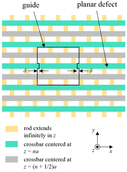
The inversion of half the lattice introduces a planar defect where the two halves meet, but this waveguide still supports a confined accelerating mode. Indeed, the mode is lossless to within the tolerance of the calculation, placing an upper bound on the loss of 0.48 dB/cm. Its fields are shown in Fig. 4.
For this mode , so using a 1550 nm source determines . The individual rods are then 158 nm wide by 200 nm tall. The mode was computed using the finite-difference time-domain method, including a uniaxial perfectly-matched layer to include losses Taflove and Hagness (2000).
III Performance of the accelerating mode
We can now explore the performance of this structure from the point of view of accelerating gradient and optical-to-beam efficiency. The gradient is limited by optical breakdown to the structure material. We can define a parameter, which is a property of the mode itself and independent of the material, which relates the accelerating gradient to the breakdown threshold of the dielectric. While the mechanism of optical breakdown is not fully understood for most materials, let us suppose that breakdown occurs when the electromagnetic energy density exceeds a certain threshold in the material. We then define the damage impedance of an accelerating mode by
where is the accelerating gradient on axis and is the maximum electromagnetic energy density anywhere in the material. Then we can write the sustainable accelerating gradient as
| (1) |
For the mode in the woodpile waveguide, we have . Optical breakdown studies in silicon have shown a breakdown threshold of at and 1 ps FWHM pulse width Cowan (2006), resulting in an unloaded accelerating gradient of 301 MV/m.
With designs for future high-energy colliders calling for beam power exceeding 10 MW, optical-to-beam efficiency is a critical parameter for a photonic accelerator. Here we compute the efficiency, and the characteristics of the particle beam required to optimize the efficiency. Unlike conventional metallic disk-loaded waveguide structures, the waveguide we consider here has a group velocity a significant fraction of the speed of light; in this case . As the particle bunch and laser pulse traverse the structure, the bunch will generate wakefields in the waveguide which destructively interfere with the incident laser pulse. Because the beam-driven wakefield has amplitude proportional to the bunch charge, wakefields limit the practical amount of charge one can accelerate: If is the bunch charge, then the energy gained by the bunch scales as , but the energy loss due to wakefields scales as . Increasing the charge too much ultimately decreases the energy gain, and thus the efficiency, of the structure. To improve the efficiency, we can embed the structure within an optical cavity in order to recycle the remaining laser pulse energy for acceleration of subsequent optical bunch trains.
To compute the efficiency, we follow the treatment described in Na et al. (2005). According to that description, the efficiency of the structure depends upon several parameters. First, the characteristic impedance of the mode, which describes the relationship between input laser power and accelerating gradient Pierce (1950), is
where is the laser power. Second, the group velocity of the mode affects the efficiency, as modes with group velocity closer to the speed of light couple better to a relativistic particle beam. This is quantified by the loss factor, which is given by Bane and Stupakov (2003)
where . An optical bunch with charge will radiate fields in the accelerating mode with decelerating gradient equal to . Finally, the Čerenkov impedance parametrizes the energy loss due to wide-band Čerenkov radiation. Following Siemann (2004), we can estimate from its value for a bulk dielectric with a circular hole of radius , which is
where is the impedance of free space. For arbitrary accelerating structures, we can let be a length characterizing the radius of the vacuum waveguide, even if the guide is not circular. In our case the aperture is rectangular, so we define the parameter by , where is the aperture area. This yields .
Following Na et al. (2005), we assume the accelerator is inside an optical cavity with a round-trip loss of 5%, and the laser pulses are coupled into the cavity through a beamsplitter with reflectivity . We consider a train of optical bunches, each with the same charge, and assume that the duration of the train is much less than the slippage time between the particles and the laser pulse inside the structure. We also assume that , where is the laser pulse duration.
As described above, trying to accelerate too much charge can reduce the efficiency of an accelerator due to wakefield effects. Therefore, for a given and , the structure has a maximum efficiency . For each , we choose to maximize . These optimum values are plotted in Fig. 5.
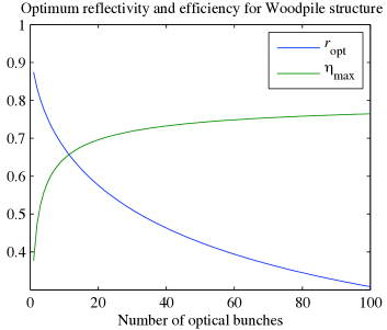
From this we see that the efficiency can be made quite high. Even with just a single bunch, the efficiency reaches 38%, while for a train of 100 bunches, the efficiency is 76%. Once the optimum is computed for each , the total train charge and external laser pulse amplitude are chosen so that they together satisfy two conditions: First, that the peak unloaded gradient is equal to the maximum sustainable gradient in the structure, which we take to be 301 MV/m from the above discussion. Second, we require that the charge maximize the efficiency. We plot the optimum charge as a function of the number of bunches in Fig. 6.
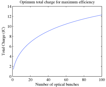
As expected from the results in Na et al. (2005), the optimum total charge is low, only 1.41 fC for a single bunch and 12.3 fC for 100 bunches. With the charge having been computed, we can then find the average initial gradient (the gradient experienced by the first optical bunch in the train) for each . We can also compute the induced energy spread on the beam as the difference between the average accelerating gradient experienced by the first and last bunches in the train, relative to the average initial gradient. These quantities are plotted in Fig. 7.
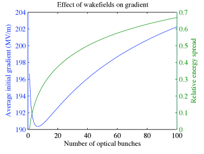
From this plot we see that wakefields have a serious effect on the acceleration. For just a single bunch, the average initial gradient is reduced from 218 MV/m (which is reduced from 301 MV/m due to the advancement of the electrons with respect to the Gaussian laser pulse envelope) to 197 MV/m. The minimum at around 7 optical bunches is due to two competing effects. First, as the number of bunches increases from the single-bunch case, the total charge increases, generating more wakefields which are recycled within the cavity. But we see from Fig. 5 that as the number of bunches increases, the reflectivity decreases, so a smaller fraction of these wakefields are recycled. More concerning is the effect on the energy spread of the beam. Even with only two bunches, the spread in gradient is 6.2%, and with 5 bunches, the spread is 16.5%.
IV Particle beam dynamics
As remarked above, we adjusted the geometry of the structure because of beam dynamics considerations, namely to make the structure symmetric in order to suppress deflecting fields. Here we examine the particle beam dynamics in this structure in more detail. Two concerns immediately arise. First, the structure has an extremely small aperture, approximately in each transverse dimension, so confining the beam within the waveguide presents a serious challenge. Second, since the structure is not azimuthally symmetric, particles out of phase with the accelerating field will experience transverse forces. As it turns out, an investigation of the second problem will yield insight into the first: The optical fields in the structure provide focusing forces which are quite strong compared to conventional quadrupole magnets and can be used to confine a beam within the waveguide. Therefore, we begin with a description of the transverse forces in the woodpile structure. We then propose a focusing scheme, and compute the requirements on the phase space extent of the particle beam.
In our analysis of the beam dynamics in this structure, we use the average of the fields over one longitudinal period of the photonic crystal waveguide. This is justified because the submicron period together with field intensities limited by damage threshold prohibits particles from acquiring relativistic momentum on the scale of a single period. To see this, one need only examine a normalized vector potential of the fields, defined by
where is the electric field magnitude. If , then the variation of a particle’s trajectory within a period is negligible, so the time-averaged force on the particle is well approximated by the force due to the longitudinally averaged fields. In our case, , so . We therefore proceed to define the longitudinally-averaged fields, as seen by a speed-of-light particle beam. Taking the fields to have time dependence, we can define the averaged electric field amplitude by
where is the complex electric field amplitude and is the Bloch wavenumber in the periodic structure. It follows that the average amplitude of the transverse force on a particle is given by
Thus essentially forms a “potential” for the transverse force. We note that the factor of implies that particles experience a transverse force to the extent that they are out of phase with the crest of the accelerating wave.
Since the mode has speed-of-light phase velocity, satisfies in the vacuum region. This implies that , so that focusing in both transverse directions simultaneously is impossible. It also means that we can expand as a polynomial in the complex coordinate . Using the symmetries of the structure, we find we can write as
| (2) |
We then have that
Thus a particle ahead in phase by () will experience focusing gradients and , in the and directions respectively, given by
| (3) |
This is equivalent to a quadrupole magnet with focusing gradient The coefficients for correspond to nonlinear forces.
To examine the implications of these forces for our structure, we extract the coefficients from the computed fields. We do so by fitting polynomials of a form similar to that in Eq. 2 for to the computed and fields; these are sufficient to compute the coefficients of the other components using the Maxwell equations. As noted in Sec. II, we have modified the structure geometry by extending the central bars into the waveguide in order to suppress the quadrupole fields. This insertion distance was determined by computing the fitted coefficient as a function of insertion distance, and finding the value for which . This prevents particles from being driven out of the waveguide by the linear focusing force, but does not yet provide a mechanism for stable propagation within such a small waveguide.
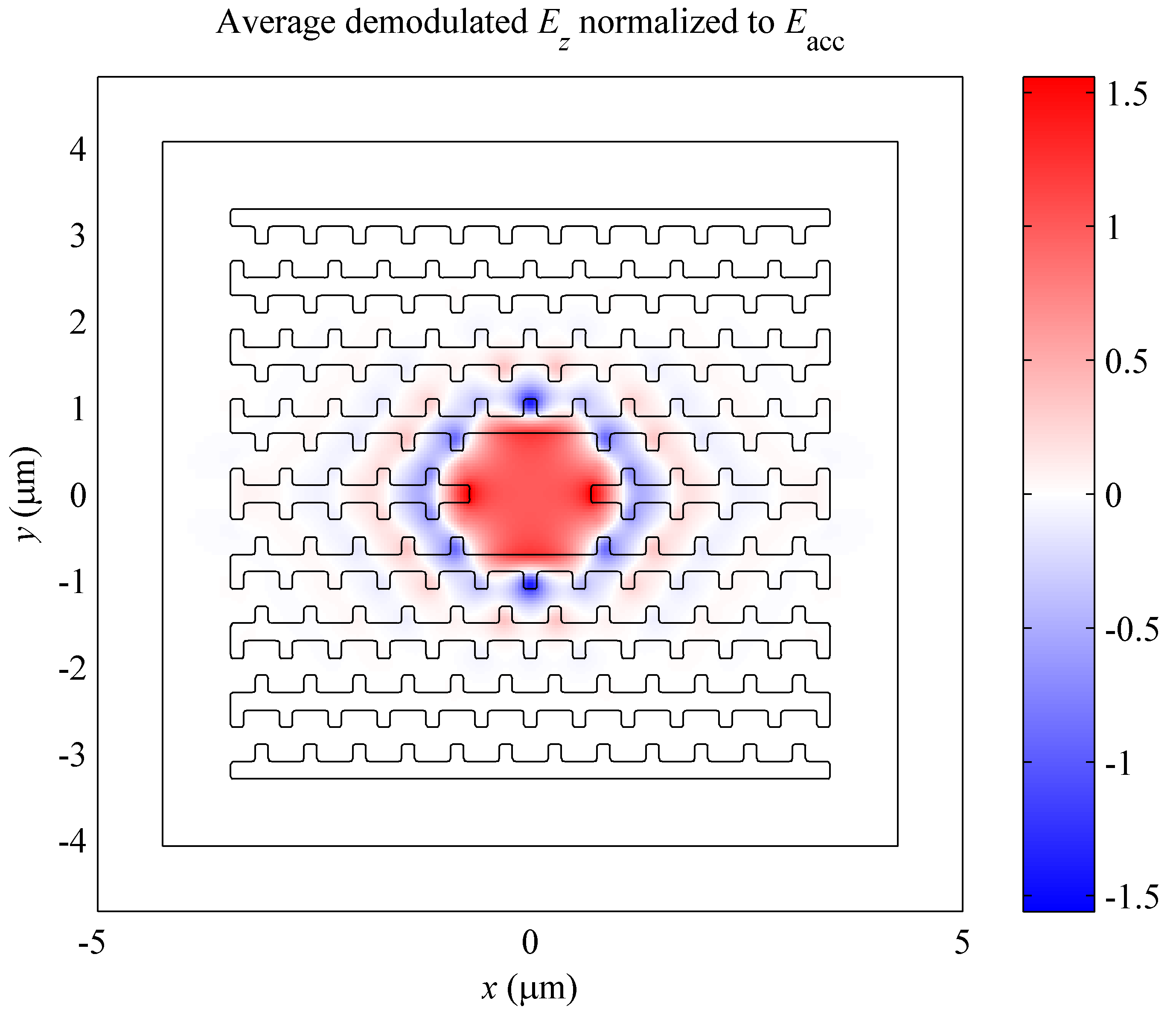
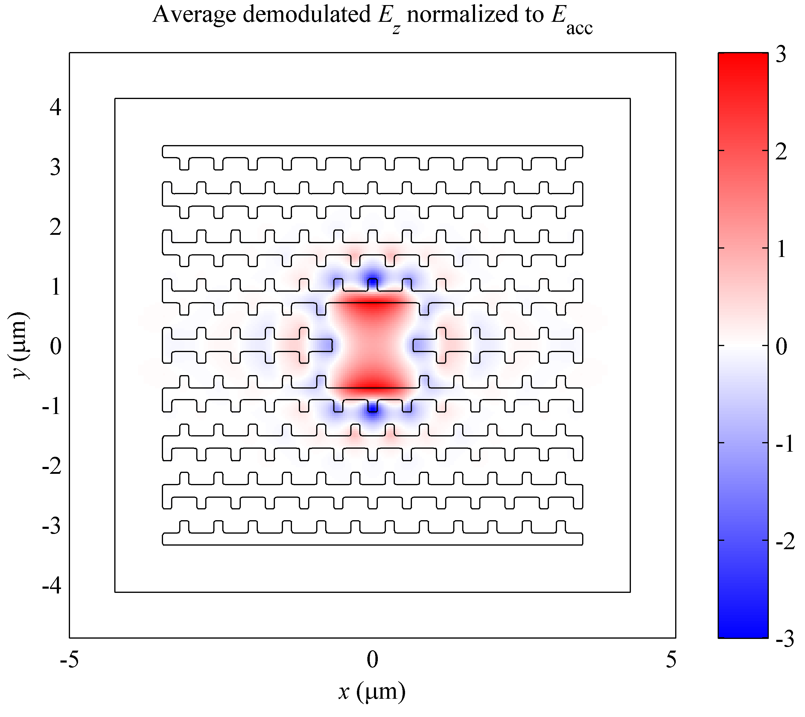
To address the question of stable propagation, we note from Eq. 3 that because of the optical scale of , the focusing gradient can be quite large. This suggests using these strong focusing forces to confine the particle beam by running a similar structure with the laser field out of phase with the particle beam. We explore this possibility by again modifying our structure by inserting the central bars, this time to optimize the fields for focusing. For this purpose we wish to suppress the lowest order nonlinear field component, in this case the octupole field given by the coefficient, for maximum stability. We find that by inserting the central bars by , we can suppress the octupole field, while the focusing gradient for fields at damage threshold is equivalent to an 831 kT/m magnet. The accelerating field for this structure geometry is shown in Fig. 8.
Having found suitable optical modes for both acceleration and focusing, we can now describe a system of focusing elements designed to confine the particle beam. We consider a focusing-defocusing (F0D0) lattice111For the remainder of this section, we refer to the F0D0 lattice as simply the “lattice,” not to be confused with the photonic crystal lattice., in which each cell consists of a focusing segment of length run behind in phase for focusing in the direction, followed by an accelerating segment of length , a focusing segment of length run behind in phase for defocusing in the direction, and then another accelerating segment of length Lee (1999). We are free to choose the parameters and . Let be the peak focusing gradient for the focusing segment, given by Eq. 3 with the energy of the ideal particle. Assuming an initial ideal particle energy of 1 GeV, we find that if we run the focusing structure at damage threshold (with an on-axis accelerating gradient of 133 MV/m), we have . For our lattice we choose , which gives a focal length of . We also choose the betatron phase advance per half-cell to be ; then . The maximum beta function value is then , the length of the unit cell is , and the betatron period is . As the particle energy increases, we consider these lengths to scale as .
The lattice described in the previous paragraph is stable under linear betatron motion. However, nonlinear transverse forces in the accelerating and focusing modes may cause instabilities which limit the dynamic aperture of the lattice and constrain the allowable emittance of the particle beam. To determine the effect of these forces and compute the required emittance of a particle beam, we perform full simulations of particle trajectories. These simulations include the dynamics of the particles in all six phase-space coordinates, with field values taken from the polynomial fits.
To compute the dynamic aperture of the lattice, we simulate particles with initial positions uniformly distributed throughout the waveguide aperture. The initial transverse momenta of the particles are taken to be 0, as are the initial deviations of the particle energies from the ideal case. We first simulate particles which are exactly on crest initially. We propagate the particles for 3 m through the lattice and record whether or not each particle collides with the waveguide edge. The initial particle positions, color-coded as to the particle’s survival, is shown in Fig. 9.
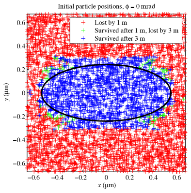
In that figure, a red marker indicates that a particle initially at that position exited the waveguide aperture within 1 m of propagation. A green marker indicates that it remained within the waveguide through 1 m, but exited before 3 m, while a blue marker indicates that the particle remained in the waveguide through all 3 m of propagation. We see from the plot that most particles that are driven out of the waveguide exited within the first meter. The figure also indicates that the dynamic aperture extends to almost the entire physical aperture of the structure (the dynamic aperture being wider in than because the initial longitudinal particle positions are at the high- point of the lattice). The initial energy of the particles is 1 GeV, and after 3 m the energy of the ideal particle is 1.87 GeV. The ellipse indicated in the figure is the ellipse of largest area which still contains only particles which remain in the waveguide. If we take this ellipse to be the boundary of the particle distribution, we can use the relation to obtain the emittance requirement of the lattice. We find normalized emittances of
| (4) |
While these emittances are several orders of magnitude smaller than those produced by conventional RF injectors, because of the small bunch charge as discussed in Sec. III, the transverse brightness (charge per phase space area) required in the optical structure is similar to that of conventional accelerators.
We can also examine the beam dynamics for particles which are slightly out of phase with the crest of the accelerating laser field. Running the same simulation as above, but with the particles given an initial phase offset, we find that the dynamic aperture is reduced as particles become further out of phase. This is shown in Fig. 10.
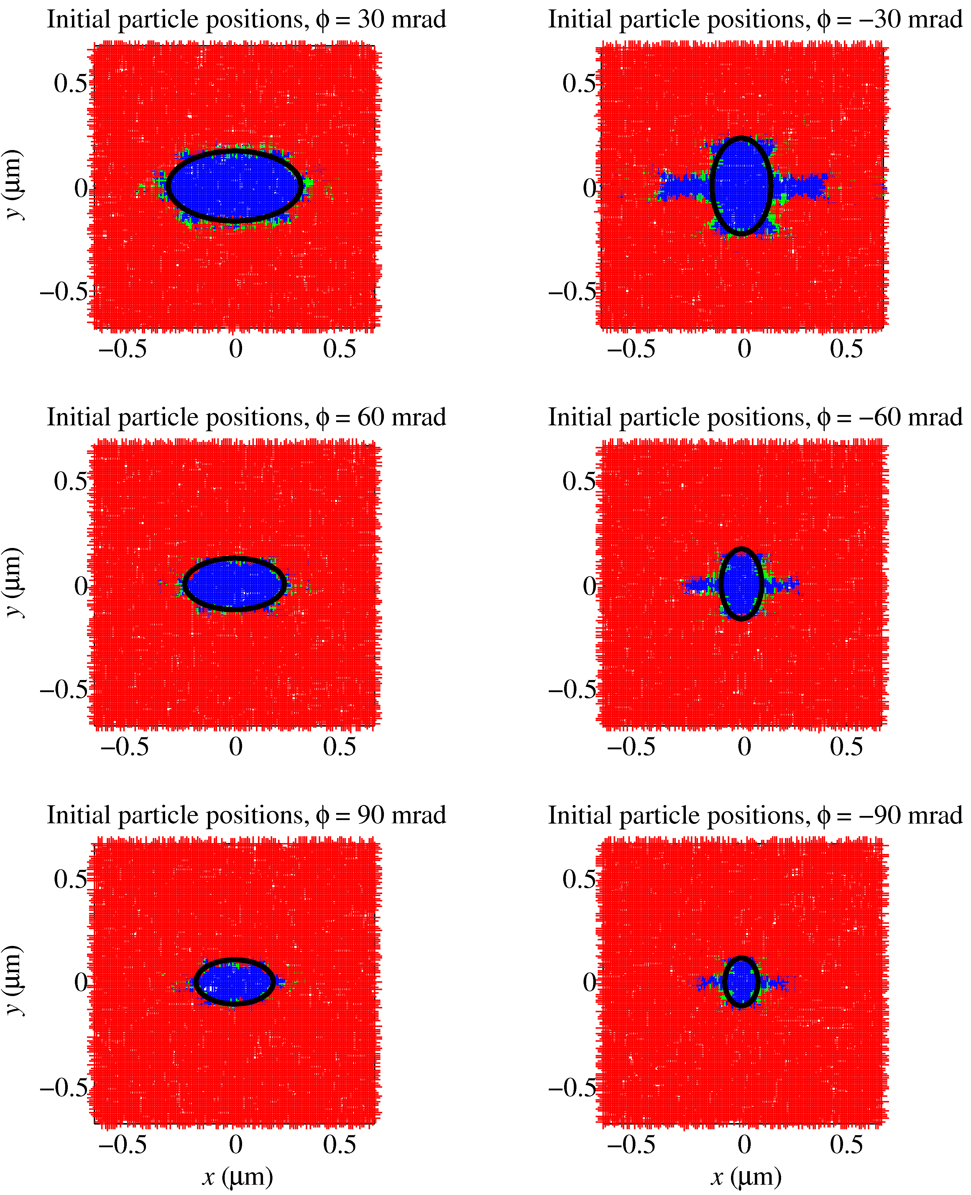
For particles ahead in phase (), we can see in the plots a pattern characteristic of a fourth-order resonance, indicating that the octupole field in the accelerating structure becomes significant as particles become off-crest. The difference in aperture shape between positive and negative phase shifts could be attributed to the sign difference of that octupole field.
With simulations of the dynamic aperture of the lattice for both on- and off-crest particles, we can now compute the dynamics of a realistic particle bunch, with variation in all six phase space coordinates. We take the initial normalized transverse emittances to be those computed above for on-crest particles and given in Eq. 4. We also take the RMS phase spread and relative beam energy deviation to be and , respectively. We track the ensemble of particles for 3 m of propagation, as before, and record the phase space coordinates every 10 cm. We find that 261 of the 13228 particles simulated, or 2.0%, exited the waveguide before completing the 3 m propagation. From the recorded phase space coordinates we can track the normalized emittances as a function of propagated distance. The transverse emittances are shown in Fig. 11.
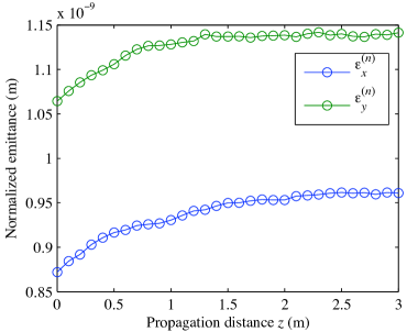
We see that the emittances increase initially, but that this increase slows as the propagation continues. For the full 3 m, increases by 10.1%, while grows by 7.3%. Thus the growth in invariant emittance is much smaller than the energy gain, so that the geometric emittance of the beam will still be adiabatically damped. This shows that particle bunches can be propagated stably in a photonic crystal accelerator without an extraordinary enhancement to beam brightness.
V Conclusion
We have found numerically an accelerating mode in a three-dimensional dielectric photonic crystal structure. This mode propagates with speed-of-light phase velocity and is confined in both transverse directions with low loss, and it is therefore suitable for acceleration of relativistic particles. Based on breakdown measurements for bulk dielectric, we estimate that the structure can sustain unloaded gradients in excess of 300 MV/m. We computed that the structure can operate with high optical-to-beam efficiency using the mechanism of recycling laser energy in an optical cavity. However, the energy spread among optical bunches in a train remains a concern; some mechanism must be found to counter this effect or such an accelerator would need to operate with less than optimum charge.
We also showed a novel method for beam confinement in a small aperture which uses optical fields in a modified structure to focus the particle beam. We found that this mechanism only required brightness comparable to conventional accelerators, and resulted in minimal emittance growth even for significant propagation distance.
Finally, while fabrication of these structures at optical lengthscales is likely to be challenging, much work on fabricating the woodpile lattice is underway in the photonics community. Woodpile lattices with a small number of layers have been constructed using a layer-by-layer technique Fleming and Lin (1999) and via wafer fusion Noda et al. (2000). Other experimental techniques, such as interferometric alignment Yamamoto and Noda (1998) and stacking by micromanipulation Aoki et al. (2003) hold promise for efficient, cost-effective fabrication.
Acknowledgements.
The author would like to thank R. Siemann, S. Fan, and A. Chao for helpful advice. Work supported by Department of Energy contracts DE-AC02-76SF00515 (SLAC) and DE-FG03-97ER41043-II (LEAP).References
- Plettner et al. (2005) T. Plettner, R. L. Byer, E. Colby, B. Cowan, C. M. S. Sears, J. E. Spencer, and R. H. Siemann, Phys. Rev. Lett. 95, 134801 (2005).
- Barnes et al. (2002) C. D. Barnes, E. R. Colby, and T. Plettner, in Advanced Accelerator Concepts: Tenth Workshop, Mandalay Beach, CA, 2002, edited by C. E. Clayton and P. Muggli (American Institute of Physics, Melville, NY, 2002), p. 294.
- Sears et al. (2007) C. M. S. Sears, E. R. Colby, R. Ischebeck, C. M. McGuinness, R. H. Siemann, J. E. Spencer, D. Walz, R. L. Byer, and T. Plettner, in Proceedings of the 2007 Particle Accelerator Conference, Albuquerque, NM, USA, 2007, edited by C. Petit-Jean-Genaz (IEEE, Piscataway, NJ, 2007), pp. 1894–1898.
- Joannopoulos et al. (1995) J. D. Joannopoulos, R. D. Meade, and J. N. Winn, Photonic Crystals: Molding the Flow of Light (Princeton University Press, Princeton, N.J., 1995).
- Li et al. (1997) D. Li, N. Kroll, D. R. Smith, and S. Schultz, in Advanced Accelerator Concepts: Seventh Workshop, Lake Tahoe, CA, 1996, edited by S. Chattopadhyay (American Institute of Physics, Woodbury, NY, 1997), p. 528.
- Kroll et al. (1999) N. Kroll, S. Schultz, D. R. Smith, and D. C. Vier, in Proceedings of the 1999 Particle Accelerator Conference, New York, NY, 1999, edited by A. Luccio and W. MacKay (IEEE, Piscataway, NJ, 1999), p. 830.
- Lin (2001) X. E. Lin, Phys. Rev. ST Accel. Beams 4, 051301 (2001).
- Cowan (2003) B. M. Cowan, Phys. Rev. ST Accel. Beams 6, 101301 (2003).
- Ho et al. (1994) K. M. Ho, C. T. Chan, C. M. Soukoulis, R. Biswas, and M. Sigalas, Solid State Commun. 89, 413 (1994).
- (10) IMRA America, Inc., URL http://www.imra.com/.
- Edwards (1985) D. F. Edwards, in Handbook of Optical Constants, edited by E. D. Palik (Academic Press, 1985), vol. 1, p. 547.
- Taflove and Hagness (2000) A. Taflove and S. C. Hagness, Computational Electrodynamics: The Finite-Difference Time-Domain Method (Artech House, Boston, 2000), 2nd ed.
- Cowan (2006) B. Cowan, in Twelfth Advanced Accelerator Concepts, Lake Geneva, WI, 2006, edited by M. Conde and C. Eyberger (American Institute of Physics, Melville, NY, 2006), pp. 837–843.
- Na et al. (2005) Y. C. N. Na, R. H. Siemann, and R. L. Byer, Phys. Rev. ST Accel. Beams 8, 031301 (2005).
- Pierce (1950) J. R. Pierce, Traveling-Wave Tubes (Van Nostrand, New York, 1950).
- Bane and Stupakov (2003) K. L. F. Bane and G. Stupakov, Phys. Rev. ST Accel. Beams 6, 024401 (2003).
- Siemann (2004) R. H. Siemann, Phys. Rev. ST Accel. Beams 7, 061303 (2004).
- Lee (1999) S. Y. Lee, Accelerator Physics (World Scientific, Singapore, 1999), pp. 48–50.
- Fleming and Lin (1999) J. G. Fleming and S. Y. Lin, Opt. Lett. 24, 49 (1999).
- Noda et al. (2000) S. Noda, K. Tomoda, N. Yamamoto, and A. Chutinan, Science 289, 604 (2000).
- Yamamoto and Noda (1998) N. Yamamoto and S. Noda, Jpn. J. Appl. Phys. 1 37, 3334 (1998).
- Aoki et al. (2003) K. Aoki, H. T. Miyazaki, H. Hirayama, K. Inoshita, T. Baba, K. Sakoda, N. Shinya, and Y. Aoyagi, Nature Mater. 2, 117 (2003).