Further author information: (Send correspondence to B.A.)
B.A.:
E-mail: bra@mpe.mpg.de, Telephone: +49 89 30000 3561
Grazing Incidence Reflection and Scattering of MeV Protons
Abstract
Treating protons as de Broglie waves shows that up to a few MeV energies protons experience total external reflection using the index of refraction concept for the target earlier applied to electrons. Angular scattering distributions can be explained by random surface scattering as known for X-rays. Applied to the Chandra and XMM-Newton X-ray telescopes the calculated reflection efficiencies can explain the observed degradation of the X-ray CCDs for both missions. Some discussion about the possibility of realizing imaging sub-MeV and MeV proton optics is presented.
keywords:
X-rays, X-ray telescopes, X-ray CCDs, X-ray scattering, particle background, Chandra, XMM-Newton, particle imaging1 INTRODUCTION
The X-ray astronomy observatory Chandra was launched into orbit in July 1999. Very early in the mission a performance degradation, predominantly with the front illuminated CCD detector ACIS-FI was noticed. Apparently some damage was done to the CCD which resulted in degradation of spectral performance due to an increase of charge transfer inefficiency (CTI)1. Investigation of the problem revealed that the most likely source for the damaging were protons with energies between 100 keV and a few MeV2. Analysis also showed that the only path for protons getting to the focal plane is through the mirror system of the X-ray telescope as the structure has more than sufficient shielding against such protons. The X-ray astronomy observatory XMM-Newton at that time was prepairing for the flight readiness review (FRR) in October 1999, and the team was badly concerned because the observatory carrys similar CCDs. Meanwhile measures have been taken to prevent the protons reaching the CCDs, like moving the device out of the focal plane (Chandra) or cover it with a solid absorber implemented on the filter wheel in front (XMM-Newton EPIC), where possible.
The scattering of protons off the mirror reflecting surfaces came totally unexpected, and the question is what physical process is at work. Rutherford scattering was considered because of the very pronounced forward scattering, and scattering by an angle of something like 0.5∘ to 1∘ is just needed. However, for a proton of 100 keV energy to get scattered by 0.5∘ it needs an electrical field of about 900 V. This is equivalent to the binding energies of the electrons in the N-shells of a Au atom, whereby Au is the coating of the XMM-Newton mirrors. Most of the interatomic space is found outside of the N-shell region. Therefore it is much more likely that the scattering angle is realized by multiple scattering processes in the coating. Computer based Monte-Carlo routines like TRIM and GEANT4 have been available but had to be substantially modified to simulate multi-scattering of a charged particle in matter under grazing incidence2,3. The dedicated measurements of proton scattering off an XMM-Newton representative flat mirror sample undertaken by Rasmussen et al.4 are quite well reproduced by the GEANT4 simulations4 within a factor of 2 to 3 as far as the efficiency is concerned. I note here that the telescopes employ two reflections or scatterings, which might increase the difference to some larger level. Details of the scattering distributions are not reproduced like a turn down of the efficiency towards low incidence angles. Measurements show a maximum at some scattering angle for fixed incidence angle4. However, at the very low angles the measurements might have had some problems, so that more detailed studies are needed to confirm the trend.
In this paper I would like to present a totally different approach to the proton scattering phenomenon using the dualism between particle and wave, treating the proton as a wave. Much of the material has been presented at several XMM-Newton emergency meetings in October 1999 prior to FRR.
2 Proton reflection
In 1924 Louis de Broglie postulated that any moving particle or object had an associated wave with wavelength = h/p. h is Planck’s constant, p is the momentum of the particle. In 1927 Davisson and Germer turned the postulate into reality, when they observed diffraction patterns of electrons reflected off the surface of crystallized nickel. The diffraction patterns also showed that the target had to have an index of refraction, which is slightly greater than unity for electrons. Subsequently the index of refraction was explained by introducing the concept of an inner potential. This is illustrated by Eqs. (1) to (6).
| (1) |
| (2) |
| (3) |
| (4) |
| (5) |
| (6) |
The particle’s phase velocity in vacuum is expressed by its energy and its momentum and mass (Equation 1). Penetrating the target the particle’s momentum is changed to because of some inner potential energy (Equation 2), and so does the phase velocity (Equation 3). The index of refraction is defined as the ratio of the two phase velocities (Equation 4). Replacing the energies by the corresponding potentials the index of refraction is given by Equation (6). is called the inner potential, is the particle’s charge. For electrons = -1, and since , . In this way has been measured for quite a number of materials, and varies between 13 V and 17 V for Ni, Pb and Ag5. There appears to be a tendency that decreases slightly with energy.
For particles with , for instance a proton, but it may be a positron or a muon or a positively charged ion, . As for X-rays, for which also , total external reflection up to a maximal grazing angle must occur. Using Snell’s law Eqs. (7) and (8) are derived.
| (7) |
| (8) |
For a proton of 100 keV energy or = 9.110-12 cm, = 42 arcmin using V0 = 15 V. This total reflection angle is about the same as the one for X-rays of a few keV energy.
The complex index of refraction can be written as
| (9) |
An index of refraction is complete only with its imaginary part , which for X-rays describes the absorption in matter. I adopt the same relation for protons, such that
| (10) |
with z being the proton penetration depth. Using Eqs. (6) and (9) we get
| (11) |
For positively charged particles with Z1, 0, and vice versa.
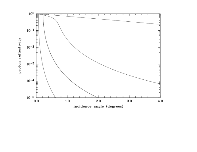
Like for X-rays the reflectance of protons is calculated using the Fresnel equations for an infinitely thin boundary. Fig. (1) shows the change of reflectance with incidence angle for some proton energies. As expected the reflectance can be very high at low incidence angles and then smoothly drops to high angles. At energies as low as 10 keV more than 20 reflectivity is achieved at an incidence angle as high as 4∘.
Because of the similarity of the reflective behaviour of X-rays and protons at their proper energies, and the index of refraction given, I have used ray tracing of both the Chandra and the XMM-Newton telescopes to compute their effective collecting areas for protons as a function of energy. Since the source of protons is diffuse and without angular structure, the source extent has been used to be 2. The grasp of the telescope is defined as proton surface number density in the focal plane per incident fluence unit, such that the product of the actual proton fluence impinging on the full telescope aperture in orbit times the grasp figure provides the proton count rate per detector area unit. For the RGS on XMM-Newton a third reflection is included which takes into account the reflection off the reflection gratings at an angle of 1.8∘. Results are shown in Fig. (2).
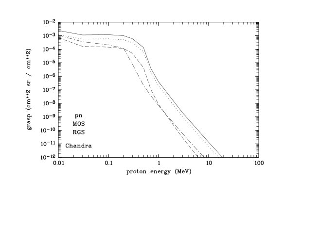
The highest grasp is obtained with the XMM-Newton telescope furnished with the pn-CCD in focus. Slightly lower, by about a factor of two, comes the XMM-Newton telescope with a MOS-CCD in focus. The reduction is due to the obstruction by the RGS gratings. The third reflection off the RGS gratings brings the grasp down by another factor of three at low energies and more than a factor of 15 at energies above 0.5 MeV. The grasp of the Chandra telescope is slightly higher than the RGS combination at energies below 100 keV, significantly higher in the 0.25 to 0.7 MeV range. This is attributed to the different grazing angles and the number of reflections involved.
3 CCD damaging and their lifetimes
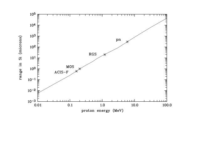
Damage to the X-ray CCDs occurs when protons dump energy in the charge transfer region, creating traps, which increase the CTI, degrade the energy resolution and ultimately render the CCD functionless when a ”lethal” dose has been reached. This happens at a load of about 109 keV cm-2 (L. Strüder, private communication). Above the charge transfer region , i.e. towards the incoming X-rays or protons, the CCDs have covering layers of Si and SiO2, the thickness of which is different for the various types of CCDs used. The ACIS-FI, or more generally the MOS based CCDs, show the thinnest layers, whereas the pn-CCD has a very thick layer, for numerical values of the thicknesses see Table (1). Protons have to have a minimum energy to traverse the top layers and to reach the charge transfer region.
Fig. (3) shows the penetration depth of protons as function of energy. Column 3 of Table (1) displays these critical energies (Ecrit). They run from 160 keV (ACIS-FI) to 6 MeV for the pn. It is interesting to note that the X-ray telescope mirrors exhibit grazing angles at which these MeV or sub-MeV protons experience total external reflection. Though designed for imaging X-rays sources these mirrors are proton telescopes as well. How good their imaging rather than collecting properties are remains to be seen.
| instrument | Si depth | Ecrit | grasp(E | Np(Ecrit) | on-CCD protons | lifetime |
| (m) | (MeV) | (cm2 sr/cm2) | (cm) | (cm | ||
| ACIS-FI | 0.6 | 0.16 | 1.310-4 | 2.1105 | 27 | 3 days |
| MOS | 1.0 | 0.2 | 5.10-4 | 1.3105 | 65 | 1 day |
| RGS | 20. | 1.2 | 3.510-9 | 2.5103 | 910-6 | 10 years |
| pn | 300. | 6.0 | 1.210-10 | 6.5 | 810-10 | 10 years |
Multiplying the grasp with the incident proton fluence gives the on-CCD proton brightness, listed in column 6 of Table (1). The fluence has been taken from an Estec document6 and represents the conditions in the XMM-Newton type of orbit. Because of lack of better knowledge the same proton fluence has been applied to ACIS-FI. Dividing the ”lethal” dose by the on-CCD proton brightness a measure for the functional lifetime of the CCDs is estimated and listed in the last column of Table (1). According to these estimates the functional lifetime of the ACIS-FI would have been just a few days, the MOS CCDs would have degraded very quickly within a day or so. These numbers explain the observed rapid degradation of the ACIS-FI; without the knowledge of the ACIS-FI problems and their explanation the protection measures against sub-MeV protons for the XMM-Newton MOSs must have been taken much faster than for Chandra when in orbit. Clearly the CCD used as detector in the RGS and the pn-CCD are pretty safe.
4 Scattering and imaging - towards a proton telescope?
So far, the proton reflection has been treated as being specular. Of course there will be scattering, both volume scattering, if the penetration depth is large, and surface scattering, if the penetration depth is short or the proton energy is low. For the surface scattering one might use the same formalism as for X-rays. This is described in Eqs. (12) and (13). The total integrated scatter for angles larger than the scattering angle increases with the surface roughness for an incidence angle and wavelength . The imaging quality of the mirror depends on the width of the point spread function and the , which results from randomly distributed surface structures. Because of the short proton wavelength, is very large for reasonable values of . For = 0.5 (equivalent to a resolution half energy width (HEW)) and = 0.5∘, 4 mÅ for a proton of 200 keV. But microroughness is a band limited quantity and related to the spatial frequency distribution of the surface (c.f. Equation (13)). For example, if the spatial resolution of the mirror is set to 1 arcmin HEW ( = 0.5 arcmin), the requirement of 4 mÅ is to be fulfilled for all spatial wavelengths d shorter than 25 nm, i.e. over a microscopic scale. Over such a spatial scale it does not seem to be impossible to reach the required microroughness of a few mÅ. Another aspect of imaging is the contrast, which is defined by the height of the central peak of the image. If one accepts a low contrast image but with a central prominent peak which contains just 0.1 of the total flux, the requirement on is reduced to about 15 mÅ over the same spatial frequency range.
| (12) |
| (13) |
| (14) |
| (15) |
For lower spatial frequencies geometric slope errors dominate the point spread function7. By X-rays the range of spatial frequencies of well polished mirrors has been explored down to scales of millimeters, shorter scales are fairly unexplored, except of upper limits of the microroughness up into the few millimeter spatial wavelength region. The region of shorter spatial wavelength scales is largely unexplored, but leaving polished mirrors aside, microroughness values of the size required may be reached on single crystals, which may actually be of macroscopic size. A double crystal arranged in a Wolter type telescope configuration may actually provide an imaging device.
Present day mirrors are likely to have much larger surface roughness in the sub-mm spatial wavelength scales (this is not an issue for high resolution X-ray mirrors), and their point spread functions are expected to be fairly broad due to the strong scattering. One can use Eqs. (12) and (13) together with Eqs. (14) and (15) to make a rough estimate about the HEW width of an up-to-date polished mirror. For such an estimate one has to make an assumption about the power spectral density (psd) as function of the spatial frequency f. Assuming psd f-γ with d f-1, reads as in Eq. (14). Equation (15) then provides the scatter angle beyond which the TIS equals q. As a numerical example one might take , E = 200 keV, = 1∘, q = 0.2 and a fairly well polished mirror, available in the lab, with = 15 Å and d0 = 3 cm, . Such wide scattering distributions are likely to be expected from polished mirrors and their metallic coatings. For the best polished mirrors with = 3 Å and d0 = 3 cm, arcmin. But it is unknown whether the psd continues down into the micron range with the power law chosen. Any residual microroughness will widen the point spread function with long tails in the scattering distribution.
Shortly before launch of XMM-Newton Rasmussen et al.4 have made proton scattering measurements with 0.3 MeV, 0.5 MeV and 1.3 MeV protons using a representative mirror sample. The measurements were done by scanning over the incidence angle at three fixed scattering angles, from which proton efficiency and scattering distribution were deduced. For all three scattering angles the peak of the scatter distribution was within 5 arcmin of twice the incidence angle, which is expected from Snell’s law and pronounced specuclar rflection. A coarse estimate of the scatter profile can be obtained from the 1.3 MeV measurements at an incidence angle of =0.7∘, which amounts to = -0.35∘ to = 1∘, i.e. a FWHM of 1.35∘. The minus sign means scattering towards the mirror, and the plus sign stands for scattering away from the mirror. At 0.3 MeV the width of the scattering distribution away from the mirror is similar. These experiments seem to confirm the proton wave model using Snell’s law, and produce a wide scattering distribution, as expected from surface scattering. The asymmetry in the scattering distribution with respect to the direction towards and away from the mirror at very shallow incidence has been observed in X-rays and is easily explained in the surface scattering theory.
5 Conclusion
Describing the proton as de Broglie wave in conjunction with an index of refraction less than one, predicts total external reflection of protons. Using the values for the inner potential observed in electron measurements allows, together with the Fresnel equations, computing of reflectance values. Total reflection at incidence angles of less than one degree occurs for protons with energies less than a few MeV. Ordinary targets, even fairly well polished mirrors, are likely to have surface mircroroughness values which lead to scattering distributions one degree or more wide. Targets with much lower microroughness for spatial wavelengths in the sub-micron region are needed, which might be realized with crystals or other materials, to use this effect for building proton optics or a proton scatterometer, with which structures in the nanometer range might be revealed. The total external reflection occurs not only for protons but for any positively charged particle, including positrons, muons and ions. In principle, there is no limit to the particle energy for total external reflection inherent to the theory presented but some experimental practical limits are coming up with the total external reflection angle as small as one arcmin, which would correspond to an energy of about 175 MeV.
6 Acknowledgments
I would like to thank Andy Rasmussen for permission of using measurement results prior to publication, and Gerald Drolshagen for permission of making public use of the cited ESA report.
REFERENCES
-
1.
G. Y. Prigozhin, S. E. Kissel, M. W. Bautz, C. Grant, B. LaMarr, R. F. Foster, G. R. Ricker, ”Characterization of the radiation damage in the Chandra x-ray CCDs”, Proc. SPIE 4140, pp. 123-134, 2000.
-
2.
J. J. Kolodziejczak, R. F. Elsner, R. A. Austin, S. L. O’Dell, S. L., in ”Ion transmission to the focal plane of the Chandra X-Ray Observatory”, Proc. SPIE 4140, pp. 135-143, 2000.
-
3.
R. Nartallo, H. Evans, E. Daly, et al., ”Radiation Environment induced degradation of Chandra and implications for XMM”, ESA report Esa/estec/tos-em/00-015/RN, 2000.
-
4.
A. Rasmussen, J. Chervinsky, J. Golovchenko, ”Proton scattering off XMM optics: XMM mirror and RGS grating samples”, Columbia Astrophysics Laboratory, Document RGS-COL-CAL-99009, 1999
-
5.
E. W. Schpolski, ”Atomphysik I”, VEB Deutscher Verlag der Wissenschaften, Berlin 1965
-
6.
H. Evans, ESA report, esa/estec/wma/he/XMM/9, 1997
-
7.
B. Aschenbach, ”Boundary between geometric and wave optical treatment of x-ray mirrors”, Proc. SPIE 5900, pp. 92-98, 2005.