Calibration systems and methods for the ANTARES neutrino telescope
Abstract
The ANTARES neutrino telescope is currently being constructed in the Mediterranean Sea. The complete detector will consist of 12 strings, supplemented by an additional instrumentation line. Nine strings are at present deployed of which five are already connected to the shore and operating. Each string is equipped with 75 Optical Modules (OMs) housing the photomultipliers to detect the Cherenkov light induced by the charged particles produced in neutrino reactions.
An accurate measurement of the Cherenkov photon arrival times as well as the positions and orientations of the OMs is required for a precise reconstruction of the direction of the detected neutrinos. For this purpose the ANTARES detector is provided with several systems to facilitate the calibration of the detector. The time calibration is performed using light pulses emitted from LED and laser devices. The positioning is done via acoustic triangulation using hydrophones. Additionally, local tilt angles and the orientations of the modules are measured with a set of tiltmeters and compasses.
In this paper, it is demonstrated that the ANTARES time and alignment calibration systems operate successfully in situ. In particular, it is shown that the ANTARES read-out electronics is capable of reaching a sub-nanosecond time resolution.
1 Introduction
The ANTARES neutrino telescope [1] is being constructed at a depth of 2.5 km in the Mediterranean Sea 40 km off shore from Toulon (France).
The complete detector will consist of 12 strings (also referred to as lines) of 450 m length with about 70 m spacing, anchored on the sea bed and maintained vertically by buoys. Each string is equipped with 75 Optical Modules [2], pressure resistant glass spheres housing a photomultiplier tube (PMT), which detects the Cherenkov light emitted by charged particles produced in neutrino reactions with the surrounding matter. The OMs of a string are arranged into triplets on 25 storeys of 14.5 m vertical distance to each other, with the PMTs looking downwards at an angle of with respect to the horizontal.
In 2006, the first ANTARES lines have been deployed and put into operation [3]. Presently, nine strings have been deployed of which five are already connected to shore and taking data continuously. The completion of the ANTARES telescope is foreseen for the beginning of 2008.
The high angular resolution for neutrino astronomy ANTARES aims at ( for muon events above 10 TeV) is intimately connected with a precise resolution of the relative arrival times of Cherenkov photons at the PMTs. The relative time resolution between OMs is therefore of importance. The time resolution is intrinsically limited by the transit time spread of the signal in the PMTs () and the optical properties of the seawater [4] such as light scattering and chromatic dispersion ( at a distance of 40 meters).
The ANTARES read-out electronics and calibrations systems are designed to contribute less than 0.5 ns to the overall timing resolution. In addition, a precise measurement of the relative positions of the OMs with an accuracy of 10-20 cm is required.
2 Time calibration
The time calibration of the ANTARES telescope is performed using several systems which provide complementary information on the propagation of the signal in the detector.
The internal clock calibration system. A precise time reference clock system has been implemented in the ANTARES detector. This system consists of an on shore 20 MHz clock generator connected via a clock distribution system to the clock signal transceiver boards integrated in each storey.
This setup allows to measure the time offsets of a storey using an echo-based time calibration whereby each storey sends back a return signal through the same optical path as the outgoing clock signal. In situ measurements show an excellent stability of . Furthermore the internal clock system facilitates an absolute event time measurement, with a precision of about , by assigning a GPS timestamp to the data. This absolute precision is more than sufficient to attribute possible astrophysical sources to the recorded neutrino events.
The internal Optical Module LEDs. A blue Agilent HLMP-CB15 LED is mounted on the back of the PMT inside the Optical Modules. The light intensity of the LEDs peaks at about 470 nm with a FWHM of 15 nm. These LEDs are used to measure the relative variation of the PMT transit time.
The Optical Beacons. The relative time calibration including the optical properties of the sea water at the ANTARES site is accomplished using LED and Laser devices, so called Beacons [5].
Four LED Beacons are distributed along every string. Each LED Beacon contains 36 individual LEDs. The Beacon LEDs have been synchronized in the laboratory to better than 0.1 ns. The light pulse emitted by the LED Beacons has a rise time of about 2.8 ns.
The Laser Beacon is a more powerful device located at the bottom of selected strings. It uses a diode pumped Q-switched Nd-YAG laser to produce pulses of with a FWHM of at a wavelength of 532 nm. The laser beam is widened by a diffuser which spreads the light out according to a cosine angular distribution. This permits to illuminate adjacent lines.
2.1 Dark room time calibration
Prior to deployment, the strings are tested and pre-calibrated in the laboratory using a dark room setup. An attenuated optical signal pulse is sent from a Nd-YAG solid state laser via an optical splitter to the OMs. One output of the splitter is connected to a reference control module that is used to relate the timing of the different OMs. The dark room calibration provides a set of calibration values for first in situ data taking and is used to cross check subsequent in situ calibrations. Additionally, a test of the clock system is performed in the dark room.
2.2 In situ time calibration
In situ time calibrations have been performed regularly using dedicated measurement setups for all of the five operating lines.
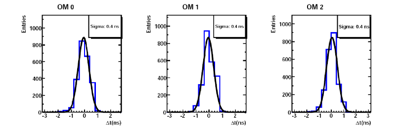
Figure 1 shows, as an example, the time difference distributions between the time of arrival of the light at the three OMs of storey 3 of Line 1 and the time of emission from the LED beacon in storey 2 on the same line. Due to the short distance between the beacon and the OMs () and the high light intensity of the beacon pulse, contributions from the transit time spread in the PMT, from the signal pulse walk, as well as light scattering and line movements are negligible. Hence, the width of the time distribution () reflects the resolution of the read-out electronics and is in agreement with the expected time resolution [6].
3 Alignment of the detector
Being exposed to the sea current, the ANTARES strings undergo drifts of several meters. Therefore, a second essential element of the calibration is the real time measurement of the OM positions within an accuracy of 10-20 cm. Again, several complementary systems are used to measure the positions of the detector elements.
Acoustic modules. The acoustic modules [7] transduce electrical signals to sound waves and vice versa. The transducing part made of a hemispherical piezo-ceramic (1 cm diameter) is referred to as hydrophone. The acoustic modules comprise emitter-receivers (RxTx) located at the anchors of ANTARES strings, receivers (Rx) located on the lines and transponders. Transponders are autonomous units located on the sea bed around the lines at some 300 m distance from each other, providing additional triangulation points to increase the precision of the measurement.
Oceanographic probes. Beside the acoustic emitters and receivers, additional instruments to measure the sound velocity at the site are needed to translate the propagation time of the acoustic signals between two modules into their distance, thus obtaining a relative positioning of the detector. The sound velocity depends on three main properties of the sea water: salinity, temperature and pressure. In order to measure the sound speed variations within the detector, ANTARES utilizes a set of sound velocimeters, conductivity, temperature and pressure probes coupled to sound velocimeters, as well as separate, independent pressure probes.
Compasses and tiltmeter systems. A system of compasses and tiltmeters on every storey of the strings supplements the acoustic positioning. The compasses measure the orientation of the storeys and the tiltmeters provide the inclination of the string.
3.1 In situ acoustic positioning
Relative positioning. The acoustic triangulation is carried out with a period of a few minutes. Triggered by the ANTARES clock system, the RxTx acoustic modules alternately send signals to the other modules being in listening mode. In addition, the triangulation using the transponders is processed separately.
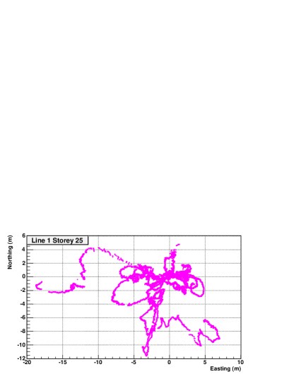
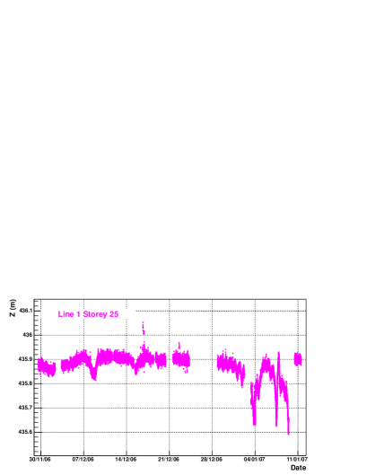
An example of the measurements is given in Fig. 2. Here, the horizontal trajectory as well as the vertical displacements of the hydrophone on top of Line 1 for a certain data period are shown, see Figure caption for further details. The accuracy of the measurement is well within the specifications.
Absolute positioning. The absolute positioning of the ANTARES telescope has been performed by acoustic triangulation of the detector elements from a surface ship equipped with a differential GPS antenna. The triangulation with the ship has been repeated at different ship positions measured by the DGPS receiver. Accuracies of about 1 m are achieved on geodetic positions of anchored detector components.
3.2 Line shape model
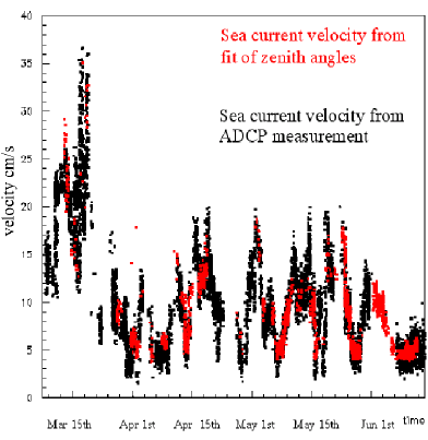
The movements of the strings are caused by the sea current. A model has been developed which allows to calculate the line shape based on the drag forces due to the sea current and the known buoyancy of the detector elements. The free parameters in this model are the sea current velocity and direction which can be fitted to the data. A comparison (see Fig.3) between the sea current velocity obtained by the model and the measurement with an Acoustic Doppler Current Profiler (ADCP) on the MILOM test line shows a good agreement for a wide range (5-35 cm/s) of sea current velocities.
4 Conclusions
In situ calibration for all five operating strings have been performed regularly. The time calibration as well as the positioning systems work well within the specifications.
It has been demonstrated that the ANTARES read-out electronics is capable of reaching a sub-nanosecond time resolution in situ.
This work is supported by the German BMBF Grant No. 05 CN5WE1/7.
References
- [1] A. Kouchner, “The ANTARES neutrino telescope: status report,” In this proceedings, 2007.
- [2] P. Amram et al., “The ANTARES optical module,” Nucl. Instrum. Meth., vol. A484, pp. 369–383, 2002.
- [3] G. Giacomelli and P. Kooijman, “ANTARES Collaboration detects its first muons,” CERN Cour., vol. 46N7, pp. 24–25, 2006.
- [4] J. A. Aguilar et al., “Transmission of light in deep sea water at the site of the ANTARES neutrino telescope,” Astropart. Phys., vol. 23, pp. 131–155, 2005.
- [5] M. Ageron, “The ANTARES optical beacon system,” 2007. Accepted for publication by Nucl.Instrum.Meth., astro-ph/0703355.
- [6] F. Feinstein, “The analogue ring sampler: A front-end chip for ANTARES,” Nucl. Instrum. Meth., vol. A504, pp. 258–261, 2003.
- [7] V. Niess, “Underwater acoustic positioning in ANTARES,” Proceedings of 29th ICRC, vol. 5, 2005.