Short-time dynamics of a packing of polyhedral grains under horizontal vibrations
Abstract
We analyze the dynamics of a 3D granular packing composed of particles of irregular polyhedral shape confined inside a rectangular box with a retaining wall subjected to horizontal harmonic forcing. The simulations are performed by means of the contact dynamics method for a broad set of loading parameters. We explore the vibrational dynamics of the packing, the evolution of solid fraction and the scaling of dynamics with the loading parameters. We show that the motion of the retaining wall is strongly anharmonic as a result of jamming and grain rearrangements. It is found that the mean particle displacement scales with inverse square of frequency, the inverse of the force amplitude and the square of gravity. The short-time compaction rate grows in proportion to frequency up to a characteristic frequency, corresponding to collective particle rearrangements between equilibrium states, and then it declines in inverse proportion to frequency.
pacs:
83.80.FgGranular solids and 45.70.CcStatic sandpiles; granular compaction1 Introduction
The dynamics of dense granular materials subjected to vibrations involves collective phenomena resulting from kinematic constraints (steric exclusions, weak spatial dimensions, …) and energy dissipation Aranson2006 . Well-known examples of the vibration-induced phenomena are compaction, convective flow, size segregation and standing wave patterns at the free surfaceKnight1993 ; aoki96 ; Clement96 ; liffman97 ; Sano2005 ; ribiere2005 ; Ciamarra2007 . Three different states can be distinguished depending on the intensity and frequency of vibrations: 1) Gas-like or fluidized state: The rate of energy input is such that there are no enduring contacts between particles and the material behaves as a dissipative gas jaeger96b ; Brennen93 ; Luding95 . 2) Solid-like state: Vibrational energy propagates through the network of enduring contacts between particles and the material undergoes slow rearrangements and progressive compaction weathers97 ; Josserand2000 ; wassgren2002 ; Kudrolli2004 . 3) Liquid-like state: Both particle migration and enduring contact networks are involved in the dynamics and various collective effects can be observed aoki96 ; ben-naim96 ; aoki96b ; liffman97 ; Hunt99 .
Vibro-compaction is the main feature of the solid-like state. Most investigated systems are unconfined granular beds (with a free surface) subjected to vertical vibrations. The vibrations behave as a source of randomness allowing the system to explore metastable configurations and to reduce its potential energy. There is, however, another mechanism which prevails in the case of confined granular materials. It is well-known that under cyclic straining, a granular material accumulates plastic deformation and the solid fraction tends to a maximum value depending on the material. This phenomenon is sometimes called ”granular ratcheting” due to the irreversible character of compaction under cyclic loading alonzo2004 ; Luding2004 ; Vandewalle2007 . In both confined and unconfined geometries, the solid fraction evolves as a logarithmic function of the number of cycles. In most work reported on vibrated granular media, the collective dynamics of the particles and the influence of various parameters related to the material or the driving system have not been investigated in all details. Moreover, in nearly all studies, spherical or nearly spherical particles in 3D or disks or polygons in 2D have been used alonzo2004 ; Azema2006 ; Vandewalle2007 .
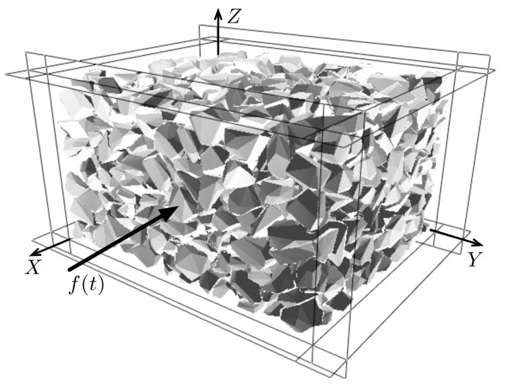
In this paper, we present a numerical investigation of the dynamics and short-time compaction of a system of irregular polyhedral particles confined inside a rectangular box with a retaining wall subjected to horizontal harmonic loading. This system is different from nearly all experimental systems investigated under horizontal vibrations since the packing remains confined inside a box, so that the gravity plays little role during the inward motion of the retaining wall. This geometry is similar to that used in various industrial applications such as the casting of fresh concrete where efficient vibro-compaction of dry and wet granular materials represents a crucial issue Swamy1976 ; Khayat2001 . The tamping operation on railway ballast is another interesting case where vibrating tamping bars are used to restore the initial geometry of the track distorted as a result of ballast settlementSAUSSINE2004 ; XIMENA2001 . With the increase of commercial speed, a better understanding of the physics of compaction is important for long time stability of ballast.
We are interested here in the evolution of the packing in the course of harmonic loading, the short-time compaction (during the first cycles) and the scaling of the dynamics with loading parameters. We used discrete-element numerical simulations by means of the contact dynamics method in 3D with rigid irregular polyhedral particles jean92 ; Moreau1994 ; Radjai1999 ; DUBOIS2003 ; Renouf2005 . The system is explored for a broad set of loading parameters including the frequency and amplitude of the harmonic driving force. A similar study was recently performed in 2D with polygonal particles Azema2006 . The passage from 2D to 3D from a purely numerical point of view involves numerical handling of particles of polyhedral shape and a higher numerical efficiency making 3D simulations over many cycles and for varying parameters possible. In this paper, we will revisit the same phenomenology as in 2D for irregular polyhedral particles. This shows that in granular materials the dynamics is not sensitive to space dimensionality although the influence of particle shape and the details of structural organization can only be appreciated in a 3D geometry.
We begin with an introduction to 3D contact dynamics method as applied to polyhedral particle shapes and the numerical procedures. Then, we present in three sections the dynamics of the packing, the evolution of solid fraction and scaling with loading parameters.
2 Numerical method
The simulations were carried out by means of the contact dynamics (CD) method with irregular polyhedral particles. In this section we present the properties of this numerical method and compare it to a more classical numerical approach molecular dynamics (MD). Then we presents the principle of the contact detection and numerical parameters which have been used for this study.
2.1 Contact dynamics
The CD method is based on implicit time integration and nonsmooth formulation of mutual exclusion and dry friction between particles in case of contact jean92 ; Moreau1994 ; Radjai1999 ; DUBOIS2003 . The equations of motion for each particle are formulated as differential inclusions in which velocity jumps replace accelerations Moreau1994 . The unilateral contact interactions and Coulomb friction law are represented as set-valued force laws according to convex analysis. The implementation of the time-stepping scheme requires the geometrical description of each potential contact in terms of contact position and its unit normal vector.
At a given step of evolution, all kinematic constraints implied by enduring contacts and the possible rolling of some particles over others are simultaneously taken into account, together with the equations of dynamics, in order to determine all velocities and contact forces in the system. This problem is solved by an iterative process (non-linear Gauss-Seidel method) which consists of solving a single contact problem, with other contact forces being treated as known, and iteratively updating the forces until a given convergence criterion is fulfilled. The method is thus able to deal properly with the nonlocal character of the momemtum transfers — resulting from the perfect rigidity of particles in contact. The CD method makes no difference between smooth evolution of a system of rigid particles during one time step and nonsmooth evolutions in time due to collisions or dry friction effects.
The MD-like methods are based on regularization schemes where impenetrability is approximated by a steep repulsive potential and Coulomb’s law by a viscous- or elastic-regularized friction law, to which smooth computation methods can be applied. In this case, the choice of viscous or elastic parameters has to be specified depending on the particle shapes. This regularization implies small time steps in order to ensure numerical stability whereas the implicit time integration method, inherent in the CD method, is unconditionally stable. The uniqueness is not guaranteed by CD approach for perfectly rigid particles in absolute terms. However, by initializing each step of calculation with the forces calculated in the preceding step, the set of admissible solutions shrinks to fluctuations which are basically below the numerical resolution. In MD-based simulations, this “force history” is encoded by construction in the particle positions.
For our simulations, we used the LMGC90 which is a multipurpose software developed in Montpellier, capable of modeling a collection of deformable or undeformable particles of various shapes (spherical, polyhedral, or polygonal) by different algorithmsDUBOIS2003 .
2.2 Simulation of polyhedral particles
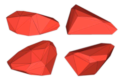
The treatment of a contact interaction between two particles requires the identification of the contact zone and a plane (in 3D), the so-called “common plane”. Obviously, for rigid particles it is possible to define this contact zone by a finite set of points. Before applying the contact detection algorithm between a pair of particles of irregular shapes (see Fig. 2), a “bounding box” method is used to compute a list of particle pairs potentially in contact. Then, for each pair, the first step is to determine if an overlap exists through a 3D extension of the “shadow overlap method” SAUSSINE2004 ; DUBOIS2003 . Several algorithms exist for overlap determination between convex polyhedra nezami2004 ; DUBOIS2003 ; Saussine2006 . In the case of an overlap, the contact plane is determined by computing the intersection between the two particles.
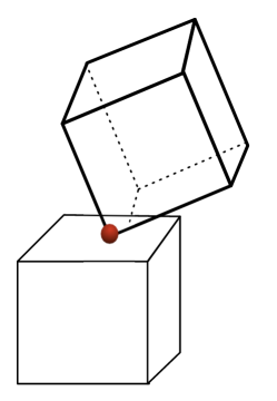
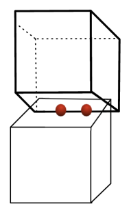
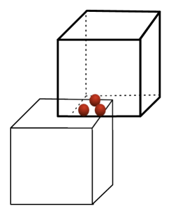
The contacts between polyhedral particles belong to different categories, namely face-face, edge-face, vertex-face, edge-edge, vertex-vertex, vertex-edge; see Fig. 1. The vertex-vertex and vertex-edge contacts are rare, i.e. in practice of “zero measure”. For each case we determine one, two or three contact points which provide a good description of the contact zone. In this paper, the vertex-edge and edge-edge contacts are referred to as “simple” contacts. On the other hand, the edge-face and face-face contacts are treated as “double” and “triple” contacts, respectively, as their representation involves 2 and 3 distinct points on the common plane. The detection procedure is fairly rapid and allows us to simulate large samples composed of polyhedral particles.
2.3 Numerical samples
Our numerical samples are composed of rigid polyhedral particles with shapes and sizes that represent those of ballast grains (Fig. 2). Each particle has at most 70 faces and 37 vertices and at least 12 faces and 8 vertices. A sample contains nearly 1200 particles. The particle size is characterized as the largest distance between the barycenter and the vertices of the particle, to which we will refer as “diameter” below. We used the following size distribution: 50% of diameter cm, 34% of diameter cm, 16% of diameter cm. The particles are initially placed in a rectangular box and compressed by downward motion of the upper wall at zero gravity; see Fig. 3. Then, the gravity is set to and the upper wall is raised 1 cm and fixed. The coefficient of friction between the particles and with the horizontal walls was fixed to 0.4, but it was 0 at the vertical walls. The coefficient of restitution between particles was fixed to zero because of the high solid fraction of the samples. One of the walls is allowed to move horizontally (x direction in Fig. 3) and subjected to a harmonic driving force. All other walls are immobile. For all simulations the time step was .
3 Vibrational dynamics
The free wall is subjected to a harmonic force as a function of time,
| (1) |
where and are the largest and lowest compressive (positive) forces acting on the wall. The first term represents the mean confining force modulated by the second term. At , the external force causes the inward motion (contraction) of the free retaining wall. Jamming occurs when the gap left between the upper wall and the free surface of the packing is filled. If is above the (gravitational) force exerted by the particles on the free wall, will be large enough to prevent the wall from backward motion (extension) during the whole cycle. Then, the granular material is in “passive state” and the major principal stress direction is horizontal nedderman92 . On the other hand, if is below the force exerted by the particles, will never be large enough to prevent the extension of the packing. This corresponds to the “active state” where the major principal stress direction remains vertical.
In all other cases, both contraction and extension occur during each period, and the displacement of the free wall will be controlled by and . Without loss of generality, we set . This ensures the largest possible displacement of the wall in the active state. Four different values of were tested, ranging from N to N.
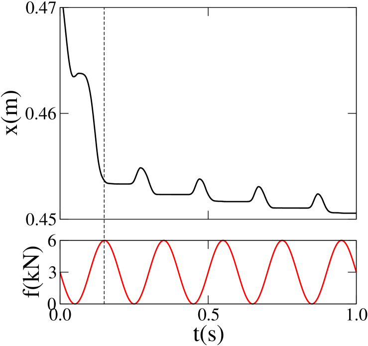
We first consider the trajectory of the free wall which reflects the dynamics of the particles in the box in response to harmonic forcing. Figure 4 shows for frequency Hz over a time interval s. We can observe a fast initial contraction ( s) followed by slow contraction over four periods. The initial contraction is a consequence of the gap left between the free surface of the packing and the upper wall. The subsequent periodic motion of the wall takes place around this jammed state and will be studied below.
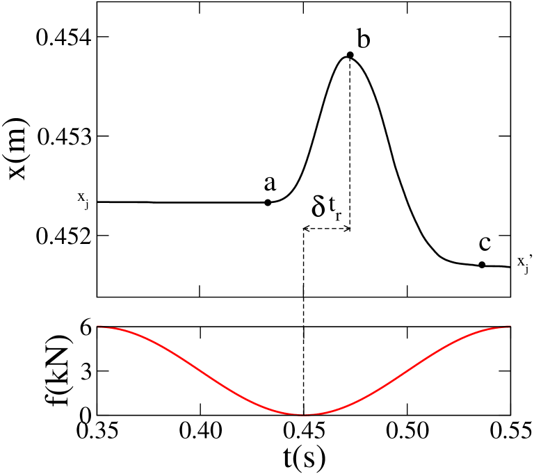
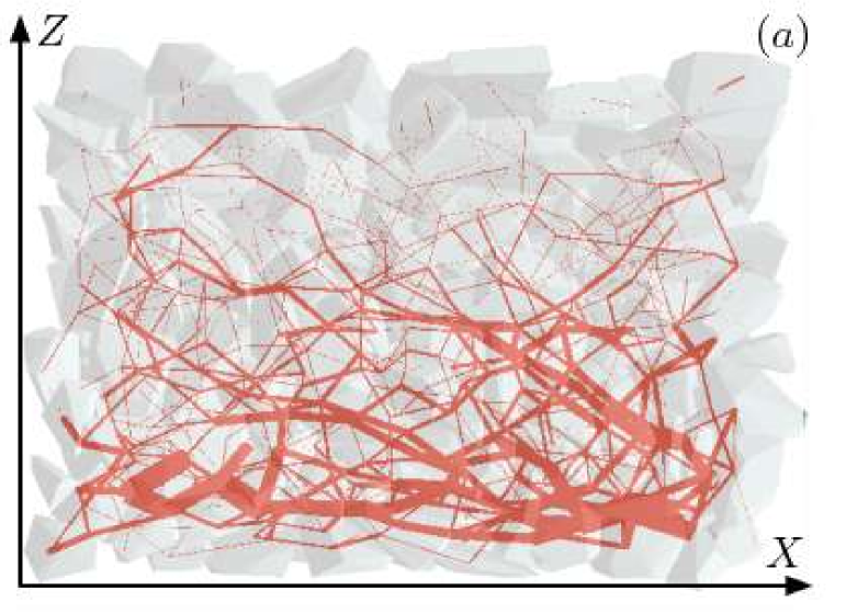
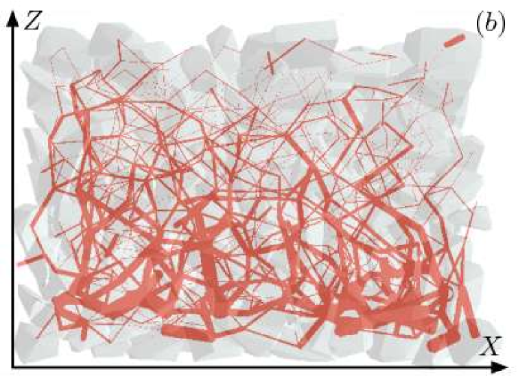
A zoom on a single period is shown in Fig. 5. It begins at the jamming position corresponding to the jamming position reached at the end of the preceding period. The motion of the wall begins (point a in Fig. 5) only when the applied force declines near to its minimum . The maximum displacement occurs at a later time (point b). From a to b, the force exerted by the packing on the free wall is above the applied force, so that the wall moves backward (extension). In this phase, the packing is in an active state. The inverse situation prevails from b to c where the particles are pushed towards the box (contraction). Then, the packing is in a passive state. The new jamming position is below the jamming position reached at the end of the preceding period. The difference represents the net compaction of the packing over one period. The particle velocity field is not a simple oscillation around an average position. The particles undergo a clockwise convective motion in the cell as shown in Fig. 6.
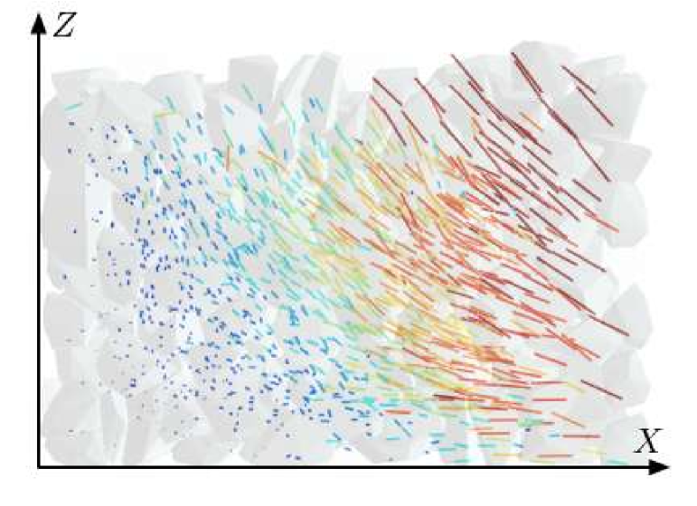

Figure 7 shows the horizontal force exerted by the packing on the wall as a function of over four periods. In the active phase, grows slightly with . In the passive phase, it grows faster and almost linearly as decreases. The vertical line corresponds to the jammed state where decreases with at . We also observe two transients : 1) unjamming and the onset of the active state, 2) jamming from the passive state. Inside the packing, the contact forces evolve between a fully jammed state, where horizontal force chains dominate (Fig. 8(a)), and the active state, where vertical gravity-induced chains can be observed (Fig. 8(b)).
4 Granular ratcheting
In our system, the solid fraction of the packing increases due to horizontal vibrations. This accumulation of plastic strain under oscillatory loading is sometimes called “granular ratcheting” alonzo2004 ; Luding2004 . To evaluate , we consider a control volume inside the box. The initial value of the solid fraction is . Figure 9 shows the evolution of the variation of solid fraction for several periods. An initial compaction of is followed by oscillations with a small increase of in each period. The initial compaction should be attributed to the initial state of the packing is not yet fully confined. We use , reached after a time laps of s, as the reference value for the evolution of solid fraction. The relative compaction of the packing is given by . The compaction rate over several periods and for a total time interval is
| (2) |
The compaction of the packing slows down logarithmically at long times ben-naim96 . But, the short-time compaction can well be approximated by a linear function with a constant compaction per period . Then, we have
| (3) |
For Hz and N, we have s-1. This rate is faster in 3D compared to 2D simulations for the same frequency Azema2006 .

It is important to note that compaction occurs in the active state, i.e. during the extension of the packing. This is shown in Fig. 10, where the variation of the solid fraction is plotted as a function of . The solid fraction increases during extension (increasing ) and decreases during contraction (decreasing ).
Granular ratcheting has been investigated by numerical simulations showing that the anisotropy of critical contacts, where the friction force is fully mobilized, plays an important role alonzo2004 ; Luding2004 . Quasi-static cyclic shearing also leads to cumulative compaction of a granular material at low strain amplitudes radjai01 ; mitchel05 . At large amplitudes, the compaction is followed by decompaction (dilation) and no net compaction can be observed over a full cycle. In our system, compaction is a consequence of unjamming and it is pursued during the whole active state. Decompaction takes place in the passive state, but it is cut short by fast jamming. The outcome of a full cycle is thus a net compaction of the packing.

5 Influence of loading parameters
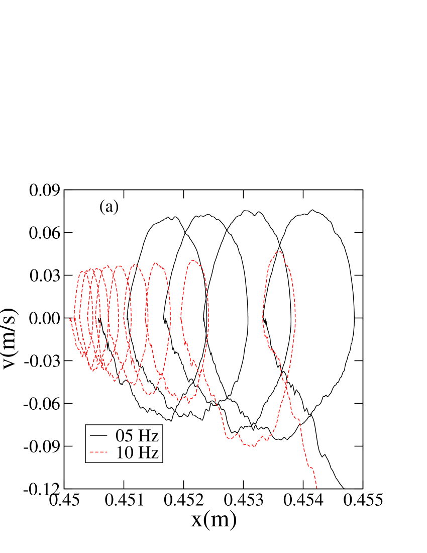
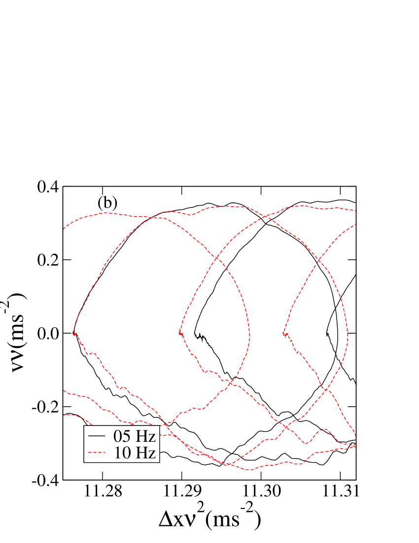
We performed a series of simulations for frequencies ranging from Hz to Hz and for a total time of 1 s. All simulations yield similar results both for dynamics and compaction. Moreover, a simple dimensional analysis leads to the collapse of the data on a single plot. Indeed, the frequency sets the time scale . Force scales are set by the largest driving force in the passive state and the particle weights as well as the smallest driving force in the active state. Hence, dimensionally, for fixed values of , and , all displacements are expected to scale with and all velocities with .
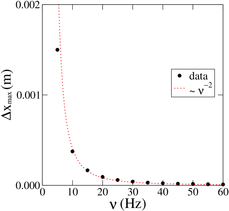
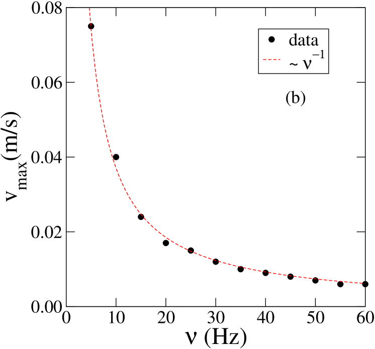
This scaling is shown in Fig. 11 where the phase space trajectory is shown for Hz and Hz without scaling and after scaling the displacements by and the velocities by . We see that the data from both simulations collapse nicely on the same trajectory after scaling. Figure 12 shows the maximum displacement in the active state and the maximum velocity in the passive state as a function of . The corresponding fits by and are excellent.
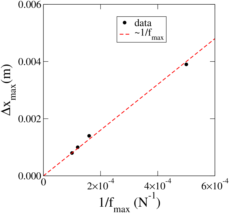
The role of force parameters , and is less evident. Since we have , we expect to be dependent on the ratio representing the relative importance of the gravitational to driving forces. Indeed, our data show that varies as ; Fig. 13. On the other hand, the mass ratio , where and are the mass of the free wall and the total mass of the particles, must control the inertia and thus the maximum displacement of the wall. Our simulations with different values of show that varies as .
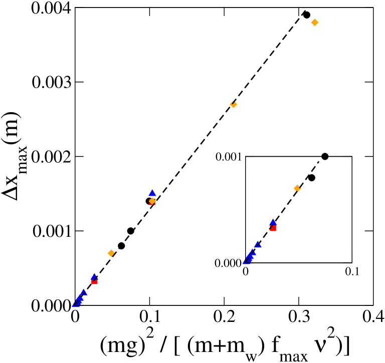
Hence, we propose the following expression for the scaling of displacements with loading parameters:
| (4) |
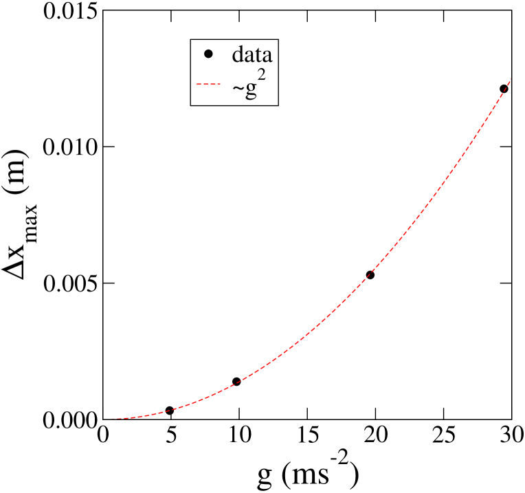
where is a dimensionless prefactor. Fig. 15 shows as a function of from different simulations with different values of , , and . We see that the data are in excellent agreement with Eq. 4. The prefactor is . This scaling is the same as in 2D simulations with a material constant for polygonal particles Azema2006 . Let us also remark that Eq. 4 predicts that varies as . This prediction agrees well with our simulation data shown in Fig. 14 for four different values of .
6 Compaction rates
We now come back to granular ratcheting and we would like to evaluate short-time compaction rates as a function of frequency. According to Eq. 3, the compaction rate varies linearly with the frequency if the total compaction per period is independent of . Fig. 16 shows as a function of . We see that only at low frequencies, increases linearly with . Beyond a characteristic frequency , declines with . The largest compaction rate occurs for Hz. The corresponding time represents the characteristic time for the relaxation of the packing. In the active state, the packing needs a finite rearrangement time to achieve a higher level of solid fraction. As long as the vibration period is longer than , the packing has enough time to relax fully to a more compact equilibrium state. But, when the period is below , the relaxation is incomplete so that , where is the largest compaction between two periods.
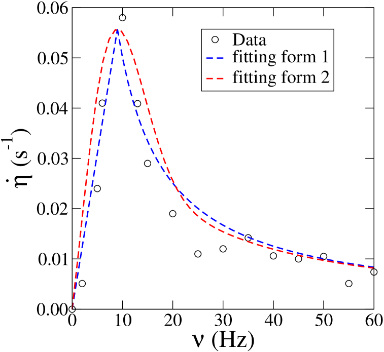
It is expected that should follow the same scaling with the frequency as the displacement of the retaining wall, i.e. . This is because the volume change is proportional to . Hence, from Eq. 3 and imposing the continuity at , we get
| (5) |
Fig. 16 shows this prediction together with the data points. We see that, although is the only fitting parameter, the compaction rate is well adjusted by Eq. 5. The prefactor is , corresponding to . In spite of the sharp transition at , it is convenient to construct a single expression containing the correct behavior both at low and high frequencies. As in 2D for polygon packings Azema2006 , the following fitting form provides a good approximation as shown also in Fig. 16 (fitting form 2):
| (6) |
The characteristic time s is of the same order of magnitude as the time required for one particle to fall down a distance equal to its diameter. Obviously, the above findings concern only short-time compaction ( s). At longer times, declines with time, but the scaling with frequency according to Eq. 5 is expected to hold at each instant of evolution of the packing.
7 Conclusion
In this paper, the contact dynamics method was employed to simulate and analyze the dynamics of a system of polyhedral particles subjected to horizontal harmonic forcing of a retaining wall. Our system is devoid of elastic elements and, hence, the behavior is fully governed by particle rearrangements. Moreover, it involves a jammed state separating passive (loading) and active (unloading) states. Dimensional analysis was used to scale the displacements with the frequency of oscillations. It was shown that the data collapse by scaling the displacements by the inverse square of frequency. We also studied the scaling with confining force and particle weights.
Granular ratcheting under horizontal vibrations was investigated. During each vibration period a small compaction of the system occurs during unloading, i.e. upon sample extension, followed by decompaction upon contraction. The compaction rate increases linearly with frequency up to a characteristic frequency and then it declines in inverse proportion to frequency. The characteristic frequency was interpreted in terms of relaxation time of the packing under its own weight during the unloading phase.
The similarity of the phenomenology of vibrational dynamics and compaction at short times in the 3D system of polyhedral particles with that of a 2D system of polygonal particles suggests that space dimensionality plays a minor role in granular dynamics. The characteristic times and compaction rates are slightly different but the scaling behavior and the functional dependence of the compaction rate with frequency are the same. A comparison with spherical particles would be interesting in order to highlight the effect of particle shapes on these parameters. On the other hand, the characteristic time appears as a crucial parameter for the compaction rate and it merits further investigation as a function of various control parameters of the system.
The authors would like to thank specially F. Dubois for interesting discussions and help with the software LMGC90. This work was supported by a grant from the Région Languedoc-Roussillon and the french railway company SNCF.
References
- (1) I. S. Aranson , Reviews of Modern Physics 78 (2006) 641-692.
- (2) J. B. Knight, H. M. Jaeger, S. R. Nagel , Phys. Rev. Lett. 70 (1993) 3728.
- (3) K. M. Aoki, T. Akiyama , Phys. Rev. Lett. 52 (1996) 3288-3291.
- (4) E. Clement, L. Vanel, J. Rajchenbach, J.Duran, Phys. Rev. E 53 (1996) 2972.
- (5) K. Liffman, G. Metcalfe, P. Cleary, Phys. Rev. Lett. 79 (1997) 4574-4576.
- (6) O. Sano, Phys. Rev. E. 72 (2005) 051307.
- (7) P. Ribière, P. Richard, R. Delannay, D. Bideau, Phys. Rev. E 71 (2005) 011304.
- (8) M. Pica Ciamarra, M Nicodemi, A. Coniglio Phys. Rev. E 75 (2007) 021303.
- (9) H. M. Jaeger, S. R. Nagel, R. P. Behringer, Reviews of Modern Physics 68 (1996) 1259-1273.
- (10) C. R. Wassgren, M.L. Hunt, P.J. Freese, J. Palamara, C.E. Brennen, Physics of Fluids 14 (2002) 3439-3448.
- (11) C.E. Brennen, S. Ghosh, C.R. Wassgren, Vertical oscillation of a bed of granular material in Powders and Grains 93 (C. Thornton, A. A. Balkema, Rotterdam, 1993) 247-252.
- (12) R. C. Weathers, M. L. Hunt, C. E. Brennen, A. T. Lee, C. R. Wassgren, Effects of Horizontal Vibration on Hopper Flows of Granular Material in Symposium of Mechanics of deformation and flow of particulate materials (C.S. Chang, A.Misra, R.Y. Liang, and M. Babic, ASCE, New-York, 1997) 349-360.
- (13) K. M. Aoki, T. Akiyama, Y. Maki, T. Watanabe, Phys. Rev. E 874-883 (1996) 874-883.
- (14) F. Alonso-Marroquin, H. J. Herrmann, Phys. Rev. Lett. 92 (2004) 054301
- (15) S. Luding, M. Nicolas, O. Pouliquen, A minimal model for slow dynamics: Compaction of granular media under vibration or shear in Compaction of Soils, Granulates and Powders (D. Kolymbas and W. Fellin, A. A. Balkema, Rotterdam, 2004) 241-249.
- (16) N. Vandewalle, G. Lumay, O. Gerasimov, F. Ludewig, Eur. Phys. J. E 22 (2007) 241-248.
- (17) S. Luding, Phys. Rev. E, 52 (1995) 4442 - 4457.
- (18) E. Ben-Naim, J. B. Knight, E. R. Nowak, J. Chem. Phys. 100 (1996) 6778.
- (19) M. L. Hunt, R. C. Weathers, A. T. Lee, C. E. Brennen, Physics of fluids 11 (1999) 68-75.
- (20) A. Kudrolli, Rep. Prog. Phys. 67 (2004) 209 - 247.
- (21) C. Josserand, A. V. Tkachenko, D. M. Mueth, H. M. Jaeger, Phys. Rev. Lett. 85 (2000) 3632 - 3635.
- (22) R. N. Swamy, H. Stavrides1, Materials and Structures 9 4 (2000) 243-253.
- (23) Kamal H. Khayat, P. Paultre, S. Tremblay, Materials Journal 98 5 (2001) 371-378
- (24) G. Saussine, Contribution à la modélisation de granulats tridimensionnels : application au ballast, Phd dissertation, Univérsité Montpellier 2, France, 2004.
- (25) X. Oviedo-Marlot, Etude du comportement du ballast par un modèle micromécanique, Phd dissertation, Laboratoire Central des Ponts et Chaussées (LCPC), France, 2001.
- (26) M. Jean, J. J. Moreau, Unilaterality and dry friction in the dynamics of rigid body collections in Proceedings of Contact Mechanics International Symposium (Presses Polytechniques et Universitaires Romandes, Lausanne, Switzerland 1992) 31-48.
- (27) J. Moreau, Some numerical methods in multibody dynamics : application to granular materials. European J. Mech. A Solids, 13(4, suppl.), pp. 93?114, 1994. Second European Solid Mechanics Conference (Genoa, 1994).
- (28) F. Radjai, “Multicontact dynamics of granular systems”, Computer Physics Communications 121-122, p.294.
- (29) M. Renouf, P. Alart, Comput. Methods Appl. Mech. Engrg. 194 (2005) 2019-2041
- (30) P. Cundall, O. Stack, Geotechnique 29 (1979) 47-65
- (31) S. Luding, Collisions and contacts between two particles, in Physics of Dry Granular Media (H. Herrmann, J. Hovi, S. Luding (ed.), 1999) 285-304
- (32) M.P. Allen, D.J. Tildesley , Computer Simulation of Liquids (Oxford University Press, 1987)
- (33) E. Azéma and F. Radjai and R. Peyroux and F. Dubois and G. Saussine, Phys. Rev. E 74 (2006) 031302.
- (34) F. Dubois, M. Jean, LMGC90 une plateforme de développement dédiée à la modélisation des problèmes d’intéraction, in Actes du sixième colloque national en calcul des structures, Vol. 1 (CSMA-AFM-LMS, Giens, 2003) 111-118.
- (35) E.G. Nezami, Y.M.A Hashash, D. Zaho, J. Ghaboussi, Computers and Geotechnics 31 (2004) 575-587.
- (36) G. Saussine, C. Cholet, P.E. Gautier, F. Dubois, C. Bohatier, J.J. Moreau, Comput. Methods Appl. Mech. Eng. 195 (2006) 2841 - 2859.
- (37) R. M. Nedderman, Statics and Kinematics of Granular Materials (Cambrige. University. Press, Cambrige) 1992.
- (38) J.K. Mitchell, K. Soga , Fundamentals of Soil Behavior (Wiley, New York, 2005).
- (39) F. Radjai, S. Roux Contact Dynamics Study of 2D Granular Media : Critical States and Relevant Internal Variables in The Physics of Granular Media (H. Hinrichsen and D.E. Wolf (ed), Wiley, 2004) 165-186.