Corner-Impact Bifurcations: a novel class of discontinuity-induced bifurcations in Cam-Follower Systems ††thanks: This work was partially supported by the European Project SICONOS IST2001-37172.
Abstract
This paper is concerned with the analysis of a class of impacting systems of relevance in applications: cam-follower systems. We show that these systems, which can be modelled as discontinuously forced impact oscillators, can exhibit complex behaviour due to the detachment at high rotational speeds between the follower and the cam. We propose that the observed phenomena can be explained in terms of a novel type of discontinuity-induced bifurcation, termed as corner-impact. We present a complete analysis of this bifurcation in the case of non-autonomous impact oscillator and explain the transition to chaos observed in a representative cam-follower example. The theoretical findings are validated numerically.
1 Introduction
Recently, much research effort has been spent to analyse the dynamics of piecewise smooth dynamical systems with impacts [5, 41]. These systems arise in many areas of engineering and applied science. A typical example is that of mechanical systems characterised by structural components with displacement constraints. Examples include bouncing or hopping robots, systems with backlash or friction, gears, vibro-impacting mechanical devices [5].
Cam-follower systems are a particularly important class of mechanical systems with displacement constraints widely used for the operation of various machines and mechanical devices [30]. Usually, their purpose is to actuate valves or other mechanisms through the movement of a follower forced by a rotating cam. For example, all types of automated production machines, including screw machines, spring winders and assembly machines, rely heavily on this kind of systems for their operation. One of the most common application is to the valve train of internal combustion engines (ICE) [18], where the effectiveness of the ICE is based on the proper working of a cam-follower system. A schematic of a single valve for a typical pushrod type engine is presented in Figure 1. Here, the cam rotation results in a linear motion imparted to the valve. The valve spring in the system provides the restoring force necessary to maintain contact between the components.
To guarantee that the follower moves as required, it is important in applications to carefully design the cam profile. Different cam geometries are used in practice ranging from circular cams to highly complex cam profiles. In general, there is now a large variety of alternative methods to select the cam profile. For example, by using constrained optimization algorithm, it is possible to use splines to obtain the cam geometry from the desired motion that the cam is required to impart on the follower (see for examples [9] and [16]). This often means that while the cam has a continuous displacement profile, it might have discontinuities in its acceleration [31].
It has been observed that, as the cam rotational speed increases, the follower can detach from the cam. This causes the onset of undesired behaviour associated to impacts taking place between the follower and the cam. For example, in automotive engines this phenomenon can seriously deteriorate the engine performance as the valves can close with abnormally high velocity and even bounce off the seat (valve floating and bouncing) [21, 37, 10]. To avoid this phenomenon, a large spring force and preload are applied to the follower [34]. This often causes an increase in the contact force, which induces higher stresses possibly leading to early surface failure of the parts. The resulting high friction valve train reduces the efficiency of the engine system [39].
In general, cam-follower systems can be thought of as impact oscillators with moving boundaries [20, 30, 15, 40]. While the dynamics of impact oscillators with continuous forcing has been the subject of many papers in the existing literature (see for example [32], [17], [6, 7]), the possible intricate bifurcation behaviour of impact oscillators with discontinuous forcing was discussed only recently, as for example in [8]. It was proposed that discontinuously forced oscillators can show a novel bifurcation phenomenon unique to their nature which was termed as corner-impact bifurcation. Namely, in [8] the dynamics are studied of an impact oscillator forced by a discontinuous sinusoidal forcing of the form . It was shown that, under variation of the system parameters, abrupt changes of the system qualitative behaviour are observed when an impact occurs at a point where the forcing velocity is discontinuous (a corner-impact bifurcation point).
The observed behaviour was explained in terms of appropriate local maps. In particular, by using the technique of discontinuity-mappings recently proposed in [17] and [12], it was suggested that a corner-impact bifurcation of the oscillator corresponds to a border-collision of a fixed point of the associated Poincaré map. An important difference was highlighted between corner-impact bifurcations and other types of discontinuity-induced bifurcations [4] in impacting systems such as grazing of limit cycles [28, 38, 22, 26, 33, 24]. While the normal form map of a grazing bifurcation is typically characterised by a square root singularity [28], the local normal form map associated to a corner-impact bifurcation was shown to be a piecewise linear map with a gap such as those studied in [19]. Hence, as explained in [8], an appropriate classification method needs to be used to investigate this novel class of bifurcations.
In [14], it was conjectured for the first time that corner-impact bifurcations are fundamental in organizing the complex behaviour observed in cam-follower systems. It was shown that, as the cam rotational speed increases, these systems can exhibit sudden transitions from periodic solutions to chaos. Such transitions were conjectured to be due to corner-impact bifurcations.
In this paper, we present a careful analysis of corner-impact bifurcations in cam-follower systems. We derive analytically the normal form map associated to such a bifurcation in a representative example of interest where the cam profile is characterised by a discontinuous acceleration. In particular, we investigate the bifurcation behaviour exhibited by this system under variations of the cam rotational speed. We find that following the detachment of the follower from the cam, the system can exhibit complex nonlinear phenomena involving chattering, period adding cascades and the sudden transition from periodic attractors to chaos. We explain the sudden transition to chaos observed in the system in terms of a corner-impact bifurcation. Namely, we show that dramatic changes in the system behaviour are observed when, under parameter variation, one of the impacts characterizing the system trajectory crosses one of the manifolds in phase space where the cam acceleration is discontinuous.
We prove that the normal form map of the corner-impact bifurcation in these systems is a piecewise linear continuous map rather than discontinuous because of the higher degree of discontinuity of the forcing signal provided by the cam with respect to that of the forcing considered in [8]. We wish to emphasize that such a finding is generic for the the wide class of impacting systems characterised by forcing terms with discontinuous acceleration.
As shown in the paper, the derivation of the mapping has an immediate practical relevance. In fact, the derivation of a piecewise linear normal form map implies that the strategy to classify border-collisions in piecewise linear continuous maps due to Feigin [13] can be used, under some circumstances, to classify corner-impact bifurcations in continuous-time impacting flows.
The rest of the paper is outlined as follows. In Sec. 2, we present the modelling of the cam follower system of our concern where the cam profile has been assumed to be characterized by a discontinuous acceleration. Then in Sec. 3 the numerical bifurcation analysis is presented under variation of the cam rotational speed. In Sec. 4 we present the analysis of the corner impact bifurcation phenomenon detected in the system and we classify the ensuing dynamics by using an appropriately derived local mapping. Finally, conclusions are drawn in Sec. 5.
2 Modelling
The formulation of an appropriate model for a cam-follower system can be a challenging task for most applications. Various models with different degrees of complexity have been proposed and extensively studied. They range from simple models with one degree-of-freedom (DOF) such as that described in [20] to complex models characterised by many DOFs, as for example the 21 DOFs model studied in [36] where additional effects of camshaft torsion and bending, backlash, squeeze of lubricant in bearings are included. Nevertheless, there is a general agreement in the literature, confirmed by experiments, that a lumped parameter single degree-of-freedom model is adequate to represent the main qualitative features of the dynamic behavior of the system of interest [3, 20, 1, 15].
The schematic diagram of the cam-follower system under investigation is shown in Figure 2. We consider the following second order equation to model the free body dynamics of the follower away from the cam,
| if , | (1) |
where , , and are constant positive parameters representing the follower mass, viscous damping, spring stiffness and the gravitational constant respectively. The state of the follower is given by the position and the velocity . The cam position is given by and we assume that the follower motion is constrained to the phase-space region where .
The dynamic behavior when impacts occurs (i.e. ) is modelled via a Newton restitution law as [5, 23, 29]:
| if , | (2) |
where and are the post- and pre-impact velocities respectively, is the projection of the cam velocity vector at the contact point along the direction of the free movement of the follower, and is the coefficient of restitution used to model from plastic to elastic impacts.
An essential ingredient of the model is the choice of the cam profile, . The cam is assumed to be rotating at a constant angular velocity and can be interpreted as the “control action” acting on the follower state as suggested in [30]. Therefore, is carefully selected in applications as a trade off between several optimality criteria dependent upon the specific device being considered and the unavoidable physical constraints present on the system.
Typically, this results in a design process where the cam profile is selected by using splines and can contain several degrees of discontinuity. For example, the cam for a single overhead camshaft valve train is designed by using quadratic splines and, as a consequence, discontinuities are present in its acceleration. In general, it is not uncommon in applications, to find cam geometries characterised by continuous cam positions and velocities but a discontinuous second-derivative [30].
In what follows, we assume the cam profile to be characterised by a discontinuous second derivative as shown in Figure 3. For the sake of brevity, the analytical expressions of the cam profile and its derivatives are reported in Appendix A. The case of a smooth cam profile with continuous first and second-order derivatives is also of interest in applications and was studied experimentally in [2].
3 Numerical bifurcation analysis
The model represented by equations (2) and (2) was found to exhibit an intricate bifurcation behaviour including the sudden transition to chaos under variation of the cam rotational speed, [14]. The presence of bifurcations and chaos was also confirmed by experiments as described in [2].
Here we briefly summarize some of the most striking behaviour exhibited by the system focusing on the abrupt transition from a one-periodic impacting solution to chaos observed when rpm.
In general, starting from low values of the system exhibits solutions characterised by permanent contact between the cam and the follower. As increases the follower is observed to detach from the cam during its evolution and then to impact with it. A typical periodic evolution with impacts is shown in Fig. 4(a) when rpm. We observe that the follower and the cam are in contact with zero relative velocity for part of the orbit (sticking) and then detach giving rise to impacting behaviour. As shown in Fig.4(b)-(c) a careful look at the follower evolution shows that a chattering sequence is present, where theoretically an infinite number of impacts accumulate in finite time. (Note that in practice chattering is associated to a large but finite number of impacts.)
Chattering can be associated to an intricate bifurcation structure. In Fig. 5(a), the location of the impacts in the cam surface is depicted for each value of , characterising the follower asymptotic solution. We see that following detachment at about 114 rpm, the follower immediately exhibits multi-impacting behaviour and chattering (characterised by the accumulation of the impact lines in the diagram onto the darker areas corresponding to the chattering accumulation points). An interesting phenomenon is the appearance of resonant peaks associated to impact lines crossing the boundaries where the cam acceleration profile is discontinuous (represented by dotted lines in the figure). A detailed analysis of this bifurcation scenario is presented in [27].
This phenomenon can be classified as due to a corner-impact bifurcation, a type of discontinuity-induced bifurcation recently described in [8]. Namely, at certain values of , one of the impacts characterising the follower motion occurs at a point on the cam profile where the acceleration is discontinuous. We shall seek to investigate analytically this phenomenon and classify the behaviour following the corner-impact event in the cam-follower system of interest. For the sake of simplicity, we focus on a different region of the system bifurcation diagram depicted in Fig. 5(c). Here a one-periodic solution characterized by one impact per period exhibits sudden transitions to chaos as is decreased below rpm. A close look at the impact bifurcation diagram in Fig. 5(c) and in the stroboscopic bifurcation diagram Fig. 5(d) shows that such transitions occur precisely when the impact characterising the solution crosses the cam discontinuity boundaries (the dotted lines in figure 5(c)). Specifically, the sudden transition to chaos is due to the corner-impact bifurcation of the periodic solution depicted in Fig. 5(e). Past the corner-impact bifurcation point the system exhibits chaotic behaviour (see for example the trajectory reported in Fig. 5(f) for rpm). The rest of this paper is devoted to the analysis of this bifurcation scenario.
4 Corner Impact Bifurcation Analysis
The numerical observations reported above indicate that a corner-impact bifurcation is causing the transition to chaos observed in the cam-follower system. Specifically, we are interested in analyzing the occurrence of the corner impact bifurcation depicted in Fig. 5(c) when rpm. Numerically, we detected that the bifurcating orbit, shown in Fig. 5(e) is a one-periodic orbit characterised by one impact per period. As the rotational speed of the cam is decreased, at the bifurcation point, the impact is observed to cross the point on the cam surface where the cam acceleration is discontinuous. To investigate this novel type of discontinuity-induced bifurcation we will construct analytically the Poincaré map of the system close to the bifurcation point. We will then study the bifurcations of the fixed point corresponding to the periodic solution of interest. A crucial point in the analysis is to assess whether the resulting map is piecewise linear continuous or not. Indeed, only if this is the case, the theory of border-collision bifurcations (see [35, 13]) can be used to classify the possible solutions branching from the corner-impact bifurcation point [25].
We use the concept of discontinuity mapping (or normal form map) recently introduced in [17], [12] to construct analytically the Poincaré map associated to the bifurcating orbit of interest. We use the cam-follower system described in Sec 3 as a representative example to carry out the analytical derivations.
4.1 Poincaré Map Derivation
We are interested in the analysis of the period one orbit at the corner-impact bifurcation point. Such orbit is sketched in figure 6. Then, close to such periodic orbit we define the stroboscopic map as the mapping from the follower state at a stroboscopic time instant to the next stroboscopic point . Without loss of generality, we assume that for , where is the period of the cam forcing cycle (note that ). Namely, we have:
| (3) |
To construct we would need to flow forward using the system evolution from to for time taking into account the possible occurrence of impacts and therefore applying Newton’s restitution law as required. Alternatively, as shown in [17], it is possible to construct as the composition of three submappings: (i) an affine transformation from the stroboscopic plane at to the plane going through the corner impact point at ; (ii) an appropriate zero-time discontinuity mapping(ZDM) on accounting for the presence of the discontinuity; and again (iii) an affine transformation from the plane at back to the stroboscopic plane at . Specifically, while and are fixed time maps that accounts for the follower evolution away from the cam as if no impact had occurred, the ZDM represents the correction that needs to be made to the system trajectories because of the presence of impacts. Figure 6 represents the global map composition. This means that we can write
| (4) |
where , will map the state from the initial condition on the stroboscopic plane to a point on the discontinuity plane as if no impacts had occurred. will then map to the point appropriately correcting the evolution for the presence of impacts (See Fig. 7). Finally , will map to a point back onto the stroboscopic plane . In so doing, as discussed in [17], [12], the effect of the system discontinuities due to impacts are all taken into account by the ZDM, , which is therefore often termed as the local normal form map in the context of the theory of discontinuity-induced bifurcations [26].
cm \linewd0.02 \arrowheadtypet:F \arrowheadsizel:0.16 w:0.08 \move(3.5 4.75) \ravec(1 .5) \rmove(-1 -0.5) \ravec(0 1) \rmove(0 -1) \ravec(1 0) \move(0 0) \rlvec(0 2.75) \move(-6 0) \avec(6 0) \move(-3 3.5) \rlvec(2 1) \rlvec(0 2) \rlvec(-2 -1) \rlvec(0 -2) \move(1 3.5) \rlvec(2 1) \rlvec(0 2) \rlvec(-2 -1) \rlvec(0 -2) \move(-1 0.75) \rlvec(2 1) \rlvec(0 1.5) \rlvec(-2 -1) \rlvec(0 -1.5) \lpatt(0.1 0.1) \setgray0.5 \linewd0.02 \move(-2 0) \rlvec(0 5) \lpatt() \setgray0 \linewd0.03 \rmove(-0.5 0.75) \rlvec(1 -1.5) \lpatt(0.1 0.1) \setgray0.5 \linewd0.02 \move(2 0) \rlvec(0 5) \lpatt() \setgray0 \linewd0.03 \rmove(0.5 1.25) \rlvec(-1 -2.5) \setgray0 \linewd0.03 \move(-1 1.5) \rlvec(2 1) \lpatt() \setgray0.5 \linewd0.02 \move(-4.8 0) \clvec(-4.5 0)(-4.2 1.5)(-4 2) \clvec(-3.9 2.25)(-3.8 2.25)(-3.75 2.25) \rlvec(0.25 0) \clvec(-3.45 2.25)(-3.35 2.25)(-3.25 2) \clvec(-3.05 1.5)(-2.75 0)(-2.45 0) \setgray0 \lpatt() \move(-0.8 0) \clvec(-0.5 0)(-0.2 1.5)(-0 2) \clvec(0.1 2.25)(0.2 2.25)(0.25 2.25) \rlvec(0.25 0) \clvec(0.55 2.25)(0.65 2.25)(0.75 2) \clvec(0.95 1.5)(1.25 0)(1.55 0) \setgray0.5 \lpatt() \move(3.2 0) \clvec(3.5 0)(3.8 1.5)(4 2) \clvec(4.1 2.25)(4.2 2.25)(4.25 2.25) \rlvec(0.25 0) \clvec(4.55 2.25)(4.65 2.25)(4.75 2) \clvec(4.95 1.5)(5.25 0)(5.55 0) \lpatt() \setgray0.5 \move(-4 2) \clvec(-3 6)(-1 6)(0 2) \lpatt() \setgray0.5 \move(0 2) \clvec(1 6)(3 6)(4 2) \lpatt() \setgray0 \linewd0.03 \move(-2 5) \clvec(-1.2 5)(-0.5 4)(0 2 ) \clvec(0.5 4)(1.2 5)(2 5) \linewd0.02 \lpatt() \setgray0.3 \move(-2 4.5) \clvec(-1.5 4.5)(-0.5 3)(0 1.25) \move(-2 4.5) \fcirf:0.6 r:0.05 \move(0 1.25) \fcirf:0.6 r:0.05 \lpatt() \setgray0.3 \move(-0.125 1.625) \clvec(0 4)(0.75 4.75)(1.25 5) \move(-0.125 1.625) \fcirf:0.6 r:0.05 \move(1.25 5) \fcirf:0.6 r:0.03 \move(0 2.75) \fcirf:0.6 r:0.05 \lpatt() \setgray0.5 \move(-4 2) \rlvec(-0.3 1.1) \move(4 2) \rlvec(0.3 1.1) \move(4 0) \fcirf:0 r:0.03 \lpatt(0.1 0.1) \rlvec(0 2) \fcirf:0 r:0.03 \move(-4 0) \fcirf:0 r:0.03 \lpatt(0.1 0.1) \rlvec(0 2) \fcirf:0 r:0.03 \textrefh:C v:T \htext(-4 -0.1)-T \htext(-2 -0.1)-T/2 \htext(0 -0.1)0 \htext(2 -0.1)T/2 \htext(4 -0.1)T \textrefh:R v:T \htext(6 -0.1)t \textrefh:R v:C \htext( -3.1 5.3) \htext( -1.1 2.1) \htext(0.9 5.3) \textrefh:R v:B \htext( -2 4.45) \textrefh:C v:B \htext( 1.35 5) \textrefh:L v:T \htext( 0.05 1.35) \textrefh:C v:B \htext( -0.1 2.9) \textrefh:L v:B \htext( -0.8 4.1) \textrefh:C v:B \htext( 1.25 1) \textrefh:L v:B \htext( -1.95 5.1) \move(-2 5) \fcirf:0 r:0.05 \textrefh:R v:B \htext( 2.05 5.1) \move(2 5) \fcirf:0 r:0.05 \textrefh:C v:T \htext( 3.55 6.1) \textrefh:L v:T \htext( 4.55 5.55) \textrefh:L v:T \htext( 4.6 4.9)
4.1.1 Derivation of and
As explained above, the maps and are defined only in terms of the free body dynamics of the follower and the cam rotating period (depending upon the cam rotational speed ). Therefore we can solve equations (2) to get an analytical expression of the flows generating the mappings of interest.
Specifically, we define
as the state vector for the follower and the cam respectively.
Then, as explained in Appendix B, the generalized solution of (2) is:
where , , , is the identity matrix, represents the system flow for time starting from the initial condition and
Note that, in general, the system flow operator can be expressed as:
| (8) |
The submapping can then be easily obtained using (4.1.1) as:
| (9) | |||||
4.1.2 Derivation of
As explained in [12], the ZDM can be obtained by an appropriate composition of backward and forward flows so that the overall time spent following backward and forward is zero. As explained earlier, the ZDM is the correction that maps the point onto the point taking into account the presence of impacts in the trajectory of interest. In what follows we assume that only one impact occurs over one cycle of the periodic orbit of interest as we suppose to be sufficiently close to the bifurcating orbit shown in Fig. 6. Figure 7 shows a schematic diagram that describes the construction of the ZDM, close to the corner-impact bifurcations. Without loss of generality we assume that the origin is placed at the Poincaré section . To derive analytically the mapping we need to perform the following steps:
-
1.
Starting from , we find the time at which the impact occurs. Namely, is obtained by looking at the difference, , between the follower position and the cam position close to . Given a vector , we indicate by its first component. Then and therefore, close to , can be obtained as the nearest solution of the equation:
(10) where .
Hence, is implicitly defined by the equation . Once, is found, the pre-impact state of the system, , can also be obtained as
(11) Note that can be either negative or positive according to whether the impact occurs to the left or to the right of .
-
2.
Using the restitution law (2), we can then write the post-impact state of the follower as
(12) where
-
3.
Finally, to obtain , we flow forward for time starting from the post-impact state found at the previous step. In so doing, the state of the follower can be computed as:
(13)
cm \linewd0.02 \arrowheadtypet:F \arrowheadsizel:0.16 w:0.08 \move(0 0) \ravec(0 5) \move(-3 0) \avec(2.5 0) \lpatt() \lpatt() \move(-2.5 0.4) \clvec(-2.2 0.5)(-1.8 0.7)(-0 2.5) \clvec(1.2 3.6)(1.5 3.7)(1.7 3.8) \linewd0.03 \lpatt() \setgray0.6 \move(-2 5) \clvec(-1.8 4.8)(-1.5 4.5)(-0.5 2) \linewd0.02 \lpatt(0.1 0.1) \setgray0.6 \move(-2 5) \clvec(-1.8 4.8)(-1.4 4.4)(0 0.75) \arrowheadsizel:0.2 w:0.1 \lpatt(0 0.2) \move(0 0.75) \ravec(-0.5 1.25) \ravec(0.5 1.24) \arrowheadsizel:0.26 w:0.08 \linewd0.03 \lpatt() \setgray0.6 \move(-0.5 2) \clvec(0.5 4.5)(0.8 4.8)(1 5) \linewd0.02 \move(-0.5 0) \fcirf:0 r:0.03 \lpatt(0.1 0.1) \rlvec(0 2) \fcirf:0 r:0.025 \move(0 0.75) \fcirf:0 r:0.025 \move(0 3.2) \fcirf:0 r:0.025 \move(0 2.5) \fcirf:0 r:0.025 \textrefh:C v:T \htext(0.1 -0.1) \textrefh:C v:T \htext(-0.5 -0.1) \textrefh:R v:T \htext(2.5 -0.1) \textrefh:L v:C \htext(0.1 0.75) \textrefh:R v:C \htext(-0.65 2.0) \textrefh:L v:C \htext(-0.4 2.0) \textrefh:L v:C \htext(0.1 3.2) \textrefh:L v:C \htext(1.8 3.9) \textrefh:L v:C \htext(-2.7 4.9) \textrefh:C v:C \htext(0 5.25)
4.1.3 Constructing the Stroboscopic Map
Composing the submappings , and given by (9) and (14), we can then construct the stroboscopic Poincaré map, , of the system close to the corner-impact bifurcation point from a generic to as:
| (15) | |||||
where is implicitly defined by the equation .
Note that the fixed point ( associated to the periodic solution existing for a fixed value of the cam period ), can be obtained by solving equation (15) for i.e.,
| (16) |
with .
In what follows we are interested in studying such mapping locally to the corner-impact bifurcation point detected when rpm, corresponding to a period s. The fixed point associated to the bifurcating orbit is These values were detected firstly numerically and then obtained analytically by solving (16) through an algebraic manipulation software (For the sake of brevity we leave out the computer algebra here).
4.2 A locally piecewise-linear continuous map
Let and be sufficiently small variations of the state and parameter from the bifurcation point . We can then linearize the map in (15) about this point as:
| (17) |
For the computation of it is essential to take into account the implicit dependance of on and . Hence, using implicit differentiation, we have
| (18) |
Using (15), we can then write
| (19) | |||||
| (20) |
Moreover, using implicit differentiation theorem, from (10) we have:
The above expression can be used to compute the remaining term in (18) as:
| (21) |
where
and .
In an analogous way, for the computation of , it is essential to take into account the implicit dependance of on and . Hence, by using implicit differentiation, we have
| (23) |
Using (15), we can then write
| (24) |
Again, from (10) we have:
that can be used to compute the remaining term in (23). Namely, we obtain:
| (25) |
where
and
Finally, substituting (20), (24) and (25) into (23), yields
| (26) |
We can then compute explicitly these quantities for the cam-follower system of interest. In particular, after some algebraic manipulation, we have:
| (27) |
and
| (28) |
Note that both the matrices and as defined by (27)-(28) depend on the value of the second derivative of the cam acceleration at the impact point. Therefore the map is actually piecewise-linear locally to the bifurcation point where the cam acceleration is discontinuous, i.e.
Then, the local map can be expressed as:
| (32) |
where
with the index indicating whether the matrices are evaluated with or .
We have established that close to the corner-impact bifurcation point, the dynamics of the follower can be studied by means of the local mapping (32).
Now, from (15), the global Poincaré map is known to be a continuous function of the cam position and velocity through the term . Moreover, the map is independent from the cam acceleration. It follows, that the map is continuous at the bifurcation point, i.e. we must have that
when
Therefore we have
Substituting the numerical values of the map parameters for the cam follower system of interest, we obtain the following analytical estimates of the map matrices:
| (37) |
| (42) |
and
4.2.1 Numerical Validation
We will now validate our numerical findings by comparing the map (32), which was derived analytically, with the numerical estimates of the mapping obtained by means of simulation and an optimized fitting algorithm close to the bifurcation point.
To derive such an estimate, we use an accurate event-driven numerical algorithm to simulate the cam dynamics over one period starting from a set of different initial conditions and parameter values. Namely, say the vector of possible perturbations of and the vector of possible perturbations of . We then simulate the cam dynamics from each of the perturbed initial conditions and parameter values to obtain the vector after one period. We repeat the set of simulation twice, once with the cam acceleration set to and once with the acceleration set to . In so doing, we obtain numerically the vectors
We then use a least-squares fitting algorithm to estimate the matrices and that minimize the error
The estimated map matrices found using this numerical strategy are
| (47) |
| (52) |
We notice that these numerical estimates are almost identical (up to at least 5 decimal places) to those obtained analytically earlier in the paper. This validates our analysis and shows the reliability of the analytical derivation used to get a leading order estimate of the Poincaré map close to the bifurcation point under investigation.
4.3 Classification of the Non-Smooth Bifurcation Scenario
We can now use the locally derived map (analytical or numerical) to classify and explain the bifurcation scenario due to the corner-impact bifurcation detected in the cam-follower system of interest. In particular, the map derived above is a piecewise linear continuous map. As the cam rotational speed is increased, the period of the forcing provided by the cam varies. Correspondingly, at the corner-impact bifurcation point (), the map fixed point undergoes a border collision. Feigin strategy for border-collision bifurcations can then be used to classify the corner-impact bifurcation scenario [13].
The idea is to start by recasting the map (32) into a canonical form following the procedure presented in [4]. Specifically,
-
1.
We eliminate the term depending on by considering an appropriate change of coordinates. In particular if we say and the coefficients of , we choose:
so that the map becomes
(56) where
with being the coefficients of .
- 2.
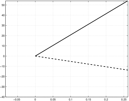
As explained in [13, 4], we can now classify the type of bifurcation scenario observed at the bifurcation point under investigation by computing the map eigenvalues on both sides of the boundary. For the case under investigation, we have that: (i) the eigenvalues of are and ; (ii) the eigenvalues of are . Hence, according to Feigin’s classification strategy, since the total number of real eigenvalues greater than unity on both sides of the boundary is odd, the bifurcating fixed point will undergo a nonsmooth saddle node bifurcation and ceases to exist [13]. This is in perfect agreement with what observed numerically as shown in Fig. 8, where the local bifurcation scenario observed in the map is shown.
Therefore, we can explain the sudden transition to chaos observed in the cam-follower system under investigation as due to the occurrence of a corner-impact bifurcation. Namely, the corner-impact is associated to a nonsmooth-fold scenario causing the disappearance of the stable impacting solution undergoing the bifurcation. This causes trajectories to leave the local neighborhood where they are confined before the bifurcation and converge towards the stable coexisting chaotic attractor when is decreased below the corner-impact bifurcation point.
Hence, we can conclude that corner-impact bifurcations in cam follower systems can indeed lead to dramatic changes of the system qualitative behavior including sudden transitions from periodic solutions to chaos.
5 Conclusions
We have studied a novel type of discontinuity-induced bifurcation in a class of mechanical devices widely used in applications: cam-follower systems. Using a representative second-order model of the follower, we have shown that its dynamics can undergo several bifurcations including sudden transitions to chaos as the cam rotational speed is varied. We analysed in detail the corner-impact bifurcation of a one-periodic solution characterised by one impact per period. In particular, we observed that the system behaviour undergoes dramatic changes when the impact occurs at a point where the cam profile is discontinuous. Using the concept of discontinuity mappings, we derived analytically the Poincaré map associated to the bifurcating orbit in the case where the cam profile has a discontinuous acceleration. Then, using the classification strategy for border-collision bifurcations, we proved that the corner-impact causes the fixed point associated to the bifurcating orbit to undergo a nonsmooth saddle-node bifurcation. Namely, the fixed point ceases to exist, with the trajectories being attracted towards a chaotic invariant set.
We wish to emphasize that:
-
•
the analysis presented above applies with minor changes to the case of impact oscillators forced by signals with discontinuous second derivative. As shown above, this leads to maps which are locally piecewise linear continuous close to a corner-impact bifurcation point. This extends the analysis presented in [8] for the case of an impact oscillator forced by a function with discontinuous first derivative. We conjecture that the properties of the local mapping depend on the degree of discontinuity of the forcing signal. This is the subject of ongoing work.
-
•
As shown in [12], discontinuity-induced bifurcations in flows are usually associated to maps which are not piecewise linear. Grazing bifurcations of limit cycles where known to be associated to maps with square-root singularities in impacting systems and Filippov systems [26] or maps with higher order nonlinear terms in the case of piecewise-smooth continuous flows (PWSC). The only cases in the literature where the map was indeed found to be piecewise linear-continuous were corner-collisions in PWSC systems and grazing sliding bifurcations in Filippov systems. So far, no evidence was given of a bifurcation event in impacting systems associated to locally piecewise-linear continuous maps. The corner-impact bifurcation scenario presented in this paper fills this gap in the literature.
-
•
We believe cam follower systems are a particularly useful set-up to show generically the behaviour of impacting systems with discontinuous forcing.
Finally, the results presented here can open a way to future work towards a better understanding of the complex dynamics of cam-follower systems. This can lead to less conservative solutions to detachment avoidance, hopefully without recurring to highly stiff closing springs and maybe active control strategies.
Acknowledgments
The authors wish to thank the anonymous reviewers whose comments led to a consistent revision of the original version of this manuscript. They also gratefully acknowledge support from the European Union (EU Project SICONOS - V Framework Programme, IST2001-37172) and the project MIUR-PRIN MACSI funded by the Italian Ministry for Research and University. The paper was completed during a research visit of the authors at the Centre de Recerca Matematica in Barcelona thanks to support from the Government of Catalunya.
Appendix A - Cam Profile
We report below the analytical description of the representative cam profile considered in this paper. As shown in Fig. 9, in this case the cam profile is the result of a geometrical based design.
The lift profile can be defined from the construction as a piecewise smooth function of the angle as:
| (61) |
where , , . Additionally, and are constant parameter given by our particular geometrical construction of the cam as (See Fig.9)
| (64) |
References
- [1] K. Akiba and H. Sakai. A comprehensive simulation of high speed driven valve trains. SAE Transactions, 810865, 1981.
- [2] R. Alzate, M. di Bernardo, U. Montanaro, and S. Santini. Experimental and numerical verification of bifurcations and chaos in a cam-follower system. Nonlinear Dynamics, Special Issue Springer Verlag, 2007.
- [3] P. Barkan. Calculation of high speed valve motion with a flexible overhead linkage. SAE Transactions, 61, 1953.
- [4] M. Di Bernardo, Ch. Budd, A. Champneys, and P. Kowalczyk. Bifurcations and Chaos in Piecewise-smooth Dynamical Systems: Theory and Applications. Springer–Verlag, 2007.
- [5] B. Brogliato. Nonsmooth Mechanics. Springer, 2nd edition edition, 1999.
- [6] Ch. Budd and F. Dux. Chattering and related behavior in impact oscillators. Phil. Trans. Royal Society London A, 347:1191–1224, 1994.
- [7] Ch. Budd, F. Dux, and A. Cliffe. The effect of frequency and clearance variations on single-degree-of-freedom impact oscillators. Journal of Sound and Vibration, 3(184):475–502, 1996.
- [8] Ch. Budd and P. Piiroinen. Corner bifurcations in non-smoothly forced impact oscillators. To appear in Physica D, 2007.
- [9] A. Cardona, E. Lens, and N. Nigro. Optimal design of cams. Multibody System Dynamics, 7:285 –305, 2002.
- [10] T. D. Choi, O. J. Eslinger, C. T. Kelley, J. W. David, and M. Etheridge. Optimization of automotive valve train components with implicit filtering. Optimization and Engineering, 1(1):9 – 27, 2000.
- [11] M. di Bernardo. Normal forms of border collisions in high-dimensional maps. In Proceedings IEEE ISCAS, Bangkok, Thailand., pages 76–79, 2003.
- [12] M. di Bernardo, C.J. Budd, and A.R. Champneys. Corner collision implies border-collision bifurcation. Physica D, pages 171–194, 2001, 154.
- [13] M. di Bernardo, M. I. Feigin, S.J. Hogan, and M. E. Homer. Local analysis of c-bifurcaiotions in n-dimensional piecewise-smooth dynamical systems. Chaos, Solitons & Fractals, 10(11):1881–1908, 1999.
- [14] M. di Bernardo, G. Osorio, and S. Santini. Chattering and complex behavior behavior of a cam-follower system. In Proc. ENOC-2005 Fifth Euromech Nonlinerar Dynamics, pages 345–354. Eindhoven, Netherlands, August 2005.
- [15] T. L. Dresner and P. Barkan. New methods for the dynamic analysis of flexible single-input and multi-input cam-follower systems. Journal of Mechanical Design, 117:151, 1995.
- [16] B. C. Fabien. The design of dwell-rise-dwell cams with reduced sensibility to parameter variation. Journal of the Franklin Institute, 332B:195 –209, 1995.
- [17] A. Nordmark H. Dankowicz. On the origin and bifurcations of stick-slip oscillations. Phisica D, 136(3-4):280–302, 2000.
- [18] J. Heywood. Internal Combustion Engine Fundamentals. McGraw-Hill, 1998.
- [19] J. Hogan, L. Higham, and T. C. L. Griffin. Dynamics of a piecewise linear map with a gap. Article submitted to Phil. Trans. R. Soc. A. London., 463:49 –65, 2006.
- [20] M. P. Koster. Vibrations of Cam Mechanisms. Phillips Technical Library Series, Macmillan Press Ltd.: London, 1974.
- [21] M. Kushwaha and H. Rahnejat. Valve-train dynamics: a simplified tribo-elasto-multi-body analysis. IProceedings of the Institution of Mechanical Engineers, Part K: Journal of Multi-body Dynamics, 214:1464–4193, 2001.
- [22] R. I. Leine, D. H. van Campen, and B. L. van de Vrande. Bifurcations in nonlinear discontinuous systems. Nonlinear Dynamics, 23(2):105–164, October 2000.
- [23] R.I. Leine, B. Brogliato, and H. Nijmeijer. Periodic motion and bifurcations induced by the painlav paradox. European Journal of Mechanics A/Solids, 21:869–896, 2002.
- [24] R.I. Leine and H. Nijmeijer. Dynamics and Bifurcations in Non-Smooth Mechanical Systems. Springer-Verlag, 2004.
- [25] A.R. Champneys M. di Bernardo, C.J. Budd. Corner collision implies border collision. Physica D, 160:222–254, 2001.
- [26] A.R. Champneys M. di Bernardo, C.J. Budd. Normal form maps for grazing bifurcations in n-dimensional piecewise smooth systems. Physica D, 154:171–194, 2001.
- [27] I. Merillas, G. Osorio, M. di Bernardo, E. Fossas, and P. Piiroinen. Complex dynamics of cam follower systems. Internal report, 2006.
- [28] A. Nordmark. Non-periodic motion caused by grazing incidence in an impact oscillator. Journal of Sound and Vibration, 145(2):279–297, March 1991.
- [29] H. Fredriksson A. B. Nordmark. Bifurcation caused by grazing incidence in many degrees of freedom impact oscillators. Proc. R. Soc. Lond., 453:1261–1276, 1997.
- [30] R. L. Norton. Cam Design and Manufacturing Handbook. Industrial Press Inc, 1st edition edition, 2002.
- [31] R.L. Norton, D. Eovaldi, J. R. Westbrook, and R. L. Stene. Effect of the valve-cam ramps on valve train dynamics. SAE paper 1999-01-0801, 1999.
- [32] F. Peterka. Impact oscillator. In Bram de Kraker Marian Wiercigroch, editor, Applied Nonlinear Dynamics and Chaos of Mechanical Systems with Discontinuities, volume 28 of A, chapter 5, pages 103,126. World Scientific Publishing Co. Pte. Ltd, 2000.
- [33] P. T. Piiroinen, L. N. Virgin, and A. R. Champneys. Chaos and period=adding; experimental and numerical verification of the grazing bifurcation. Journal of Nonlinear Science, 14:383–404, 2004.
- [34] E. Raghavacharyulu and J.S. Rao. Jump phenomena in cam-follower systems a continuous-mass-model approach. American Society of Mechanical Engineers, Proceedings of the Winter Annual Meeting, pages 1–8, 1976.
- [35] C. Grebogi S. Banerjee. Border collision bifurcations in two-dimensional piecewise smooth maps. Physical Review E, 59(4):4053–4061, April 1999.
- [36] S. Seidlitz. Valve train dynamics - a computer study. SAE Transactions, 890620, 1989.
- [37] M. Teodorescu, V. Votsios, H. Rahnejat, and D. Taraza. Jounce and impact in cam-tappet conjunction induced by the elastodynamics of valve train system. Meccanica, 41(2):157 – 171, 2006.
- [38] M. D. Todd and L. N. Virgin. An experimental impact oscillator. Chaos, Solitons and Fractals, 8:699–714, 1997.
- [39] T. S. Tumer and Y. Samim Unlusoy. Nondimensional analysis of jump phenomenon in force-closed cam mechanisms. Mechanism and Machine Theory, 6:421–432, 1991.
- [40] H. S. Yan, M. Tsai, and M. H. Hsu. An experimental sudy ofthe effect of the cam speed on cam=follower systems. Journal of Mech. Mach. Teory, 31:397=412, 1996.
- [41] Zh. Zhusubaliyev and E. Mosekilde. Bifurcations and Chaos in Piecewise-Smooth Dynamical Systems: Applications to Power Converters, Relay and Pulse-Width Modulated Control Systems, and Human … Series on Nonlinear Science, Series a). World Scientific, 2003.