Phase and alignment noise in grating interferometers
Abstract
Diffraction gratings have been proposed as core optical elements in future laser-interferometric gravitational-wave detectors. In this paper we derive equations for the coupling between alignment noise and phase noise at diffraction gratings. In comparison to a standard reflective component (mirror or beam splitter) the diffractive nature of the gratings causes an additional coupling of geometry changes into alignment and phase noise. Expressions for the change in angle and optical path length of each outgoing beam are provided as functions of a translation or rotation of the incoming beam with respect to the grating. The analysis is based entirely on the grating equation and the geometry of the setup. We further analyse exemplary optical setups which have been proposed for the use in future gravitational wave detectors. We find that the use of diffraction gratings yields a strong coupling of alignment noise into phase noise. By comparing the results with the specifications of current detectors we show that this additional noise coupling results in new, challenging requirements for the suspension and isolation systems for the optical components.
pacs:
04.80.Nn, 07.60.Ly, 42.79.Dj, 95.55.YmKeywords: Article preparation, IOP journals
1 Introduction
The search for gravitational waves has led to a new class of extremely sensitive laser interferometers. The first generation of large-scale laser-interferometric gravitational wave detectors [1, 2, 3, 4] is now in operation with the aim of accomplishing the first direct detection of gravitational waves. Simultaneously, new interferometer concepts are evaluated for future detectors.
Traditionally, partly transmissive mirrors are used in interferometers to split and combine coherent optical light fields. For high precision laser interferometers, such as for gravitational wave detection, non-transmissive reflection gratings offer a useful alternative way of splitting and combining. The resulting all-reflective interferometers are beneficial because, firstly, they reduce the impact of all thermal issues that are associated with absorbed laser power in optical substrates and, secondly, they allow for opaque materials with favourable mechanical and thermal properties. With these two qualities all-reflective interferometer concepts have, in principle, great potential to become key technologies for enhancing the sensitivity of future generations of laser interferometric-gravitational wave detectors.
From a functional viewpoint every partly transmissive mirror within an interferometer can be substituted by an appropriate reflection grating because of its analog input-output phase relations. However, the geometry of the interferometer changes considerably when diffraction gratings are used. In this context several interferometer concepts based on gratings have been proposed [5, 6] and some of them have been demonstrated experimentally [7, 8, 9]. Also the influence of a grating structure on the mechanical quality factor of a test mass has been studied [10]. Here we investigate how certain peculiarities of grating interferometers affect their ability to reach high strain sensitivities. In particular we derive formulae for the alignment noise of such interferometers.
Grating movements within these interferometers or beam movements on the grating affect the phase of the light differently than movements of mirrors and beam splitters in conventional interferometers. This is due to the reduced symmetry that diffraction gratings show compared to mirrors. Usually, the test masses in gravitational wave detectors show cylindrical symmetry, therefore their roll movement is of no concern. Gratings are merely invariant against translational displacement in direction parallel to the grating grooves, but certainly not for rotation. Therefore roll movement can be considered an additional degree of freedom that will be treated here. Moreover, a translational displacement of a grating parallel to its surface in direction perpendicular to the grating grooves will induce a phase shift [11] to the reflected light.
After a brief review of known all-reflective interferometer concepts we derive analytic expressions that describe the phase effects for various motions of optical components in the particular interferometer and compare them to the well known ones for conventional interferometers.
1.1 Gratings as functional optical elements in interferometers
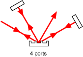
A surface with a periodic modulation of optical properties, so-called grooves, defines a diffraction grating. Let’s have a look at Figure 1 and consider incident light of wavelength in the plane perpendicular to the grating grooves and its surface. For a grating period and an incidence angle of , measured from the grating normal, the angle of the th diffraction order is given by the well-known grating equation
| (1) |
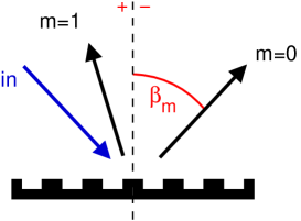
For transparent materials the orders will exist in transmission and reflection. One obtains an all-reflective beam splitter when the grating is combined with a high reflectivity coating, or transmitted orders are suppressed by some other means. The existence of higher orders depends on the choice of and . For our purposes only one or two additional orders are required, so that .
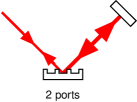
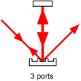
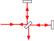
For appropriately chosen parameters there is only one additional diffraction order and no degeneracy of ports thus one obtains the analog to a four-port mirror. This device enables, for instance, an all-reflective version of a Michelson interferometer as shown in Figure 2, provided that the efficiencies for the specular reflection and for the diffraction into the first order are roughly the same.
The analog to a transmissive mirror with two ports (in the case of normal incidence) is given by a first-order Littrow configuration. In this case also only one additional order exists but the diffracted beam coincides with the incoming beam . An all-reflective linear Fabry-Perot interferometer can be constructed, also shown in Figure 2. The maximal finesse of such a cavity is limited by the first-order diffraction efficiency of the grating that is used to couple light to the cavity.
Parameters can likewise be chosen to allow for a second-order Littrow configuration (two additional orders and ). This results in a beam splitter with three ports, which can also be used to construct a linear Fabry-Perot interferometer (Figure 2). Its maximal finesse is limited by the specular reflectivity of the grating rather than the diffraction efficiency. Such a three-port splitter has no simple analog to a conventional transmissive mirror and its input-output phase relations are more complex [12]. However, the resulting properties of such resonators are well understood and controllable [13].

Linear Fabry Perot Cavity
Michelson Interferometer
2 The geometry of the optical setup
In this section we consider the effects of geometry changes, namely translations and rotations of the grating or the incident beam away from the initial, correctly aligned setup. We derive the mathematical relation between each geometry change and the change in optical path length, tilt and translation of the outgoing beam. In the following we often use the word beam when referring to the light fields interacting at the grating. However, it should be noted that all computations are based on the assumption of plane waves and infinite sized gratings. Furthermore we only consider an idealised reflection grating while any influence from a diffractive coating is neglected. The purpose of this is to summarise the differences between the ideal grating and ordinary (ideal) mirrors or beam splitters.
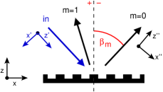
Unless otherwise noted, the grating is located in a three-dimensional coordinate system such that the impinging beam hits the grating at the origin with the grating lying in the - plane and the grating structure (grooves) being parallel to the -axis. Thus, the nominal use of the grating requires the incoming beam to be in the - plane. The incoming and outgoing beams can be defined by unit vectors in the direction of propagation and respectively. In addition, it is useful to define coordinate systems based on the incoming and outgoing beam in the perfectly aligned systems: The coordinate system of the incoming beam (denoted as ) is rotated with respect to the coordinate system of the grating by an angle around the -axis with being the angle of incidence. The coordinate systems of the outgoing beam will be denoted as (see Figure 3). In a well-aligned system the coordinate system of an outgoing beam is rotated with respect to that of the grating around the -axis by the angle .
Any change of the geometry of the optical setup can change the angle of the outgoing beams as well as the longitudinal phase (optical path length). The change in optical path length between the initial setup and the respective new geometry will be denoted as .
For a description of diffracted beams in three dimensions the commonly used scalar grating equation is not adequate. Instead we will base the following on the grating equation in vector form which, for a reflective grating (in vacuum) reads:
| (2) |
with the normal vector of the grating and the unit vector in the direction of the grooves. In the aligned setup we can set and :
| (3) |
We can write this in separate equations for the vector components:
| (4) |
Here, is not directly defined through the cross product but is given by the definition of and as unit vectors.
3 Alignment of the outgoing beam
3.1 Translation
The translations of the grating along and have no particular effect on the geometry of the outgoing beam, only a translation of the grating along the -axis by an amount will translate the outgoing beam along the axis. From three triangular equations:
| (5) |
We obtain:
| (6) |
3.2 Rotation
There are three independent degrees of freedom for rotating the incoming beam. However, in this work we restrict the analysis to rotations around and and neglect the influence of changes in the direction of polarization. At the same time we want to know the effects of a rotation of the grating around the three axes of its coordinate system. In the following we will first consider a rotation of the incoming beam by around the axis and around the axis and compute the resulting rotation of the outgoing beam ( around axis and around axis). Later we will derive all other alignment relations from this result.
We project the unit vector of the incoming beam to the coordinate system of the grating and get:
| (7) |
We can compute the vector in the direction of any outgoing beam using the grating equation (4). From the condition for the coordinate we can immediately compute :
| (8) |
The projection on can thus be written as:
| (9) |
The minus sign originates from the fact that we consider a reflection grating which turns the direction vector; e.g. for we must obtain . Using the above and the grating equation we get:
| (10) |
For small we can write:
| (11) |
Rotation of the incoming beam around the -axis:
For small rotations of the incoming beam by around the axis we obtain:
| (12) |
Rotation of the incoming beam around the -axis:
A single rotation by around the axis yields:
| (13) |
Rotation of the grating around the -axis:
In order to compute the effect of a rotation of the grating around its normal by an angle we again make use of the vectorial grating equation (2). In this case the unit vector along the direction of the grooves is given as and we obtain the following set of equations:
| (14) |
With the input beam aligned we can use the following projections and . This leads to:
| (15) |
For small we can approximate the rotation around the axis as:
| (16) |
We can derive as before; for small we obtain:
| (17) |
This shows that in first order the roll motion of the grating will couple into a rotation of the beam around the axis. The order of magnitude is the same as for a tilt motion of the grating (or mirror). Thus in contrast to a reflective element the suspension of a grating must be designed such that the roll motion is suppressed to the same level as the other two rotational degrees of freedom.
In addition, during installation and pre-alignment one must ensure the right roll angle for the grating. In the case of the VIRGO detector [14], where the pre-alignment requires to align a diffracted beam with an accuracy of 30 cm to a mirror 3 km far away, the grating would have to be positioned correctly with:
| (18) |
The precision and dynamic range of the pre-alignment control must be designed such that any initial mis-orientation larger than this can be corrected. This can be achieved already with technology used in current gravitational-wave detectors.
Frequency Change:
It is worth noting that a change of the laser frequency will also result in a grating specific change in the angle of the outgoing beam. In an otherwise aligned setup this is given by:
| (19) |
Hence
| (20) |
with the speed of light. By using typical values for the frequency stability in gravitational wave detectors we can show that in this case this effect can usually be neglected:
| (21) |
4 Optical path length
The optical path length is neither affected by the alignment of the grating nor by a translation of the grating along the axis. It only shows a dependence on and .
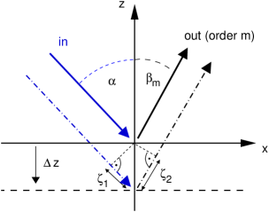
The optical path length change following a translation of the grating by can be computed from the geometry alone, see Figure 4:
| (22) |
The minus sign reflects the definition of the phase change: The optical path length must become larger when the grating is moved towards smaller ().
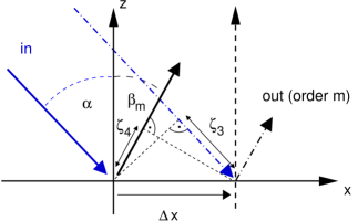
Also the translation of the grating along the -axis introduces a change in the optical path length. This phase change is rather counter-intuitive [11] but follows similarly from the geometry of the problem. The bottom plot in Figure 4 shows two parallel rays diffracted by the grating. These rays are understood to be components of the same plane wave. By definition both rays have the same phase (modulo ) in every reference plane perpendicular to their direction of propagation. However, if we assume no (or a constant) phase change at the grating surface and follow the rays through the system to a reference plane in the outgoing field we will obtain a phase difference between the two rays of
| (23) |
(please note that as shown in Figure 4 would be negative). This has two implications for the phase of the diffracted beam:
-
•
the diffraction at the grating must advance or retard the phases for those parts of the plane wave that hit the grating with a spatial distance to a chosen reference.
We can follow that the grating introduces a change in the optical path length as:
(24) -
•
We can for example define the center of the incoming wave such that the phase of the center ray can be computed by following the ray path through the system. A lateral displacement of the incident wave will then change the phase of the outgoing beam by the same amount with as the displacement of the wave projected on the grating surface.
Using the grating equation we can also write (23) as:
| (25) |
It should be clear that a translation of the grating by is equivalent to a translation of the incoming wave. Hence we can conclude that a translation of the grating produces also a change of the optical path length as stated in (25). However, due to the periodic symmetry of the grating all measurable quantities must be identical for and with an integer. Thus, in this case, the change in the optical path length is periodic with Equation 25 being defined for a translation of less than one grating period, i.e. is periodic with a period of .
It is possible to find an eigenvector such that for a translation of the grating along this vector the change of the optical path length is zero [15]. By comparing the gradient of the path length change for translations parallel to and we find a vector along which the change in optical path length cancels ().
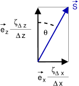
We take the ratio between the slopes of the optical path length change for and :
| (26) |
The unit vector for motion with exactly compensating changes of the optical path length must be perpendicular to as shown in Figure 5; the direction of is defined by the angle which defines the bisection between the incoming and the diffracted beam.
Hence a translating of the grating perpendicular to the bisection of the input and diffracted wave vector yields no change in the optical path length. This fact can be utilised for example by carefully choosing a mounting and seismic isolation strategy such that the translational degree of freedom containing the largest amount of (seismic) noise is made perpendicular to the bisection of the incoming and one outgoing beam. However, the fact that the axis for zero phase change can only be chosen with respect to one pair of beams and that it cannot be perpendicular to an incoming beam makes it impossible to avoid all couplings of alignment noise into phase noise for higher diffraction orders, especially for a mis-alignment of the incoming beam.
5 Alignment noise in exemplary optical setups
In this section we will compute the coupling of alignment noise into phase noise for a few simplified, exemplary optical setups. The optical systems are analysed in the plane perpendicular to grating grooves, ignoring the second alignment degree of freedom of each optical component.
We will compare the phase noise due to component or beam misalignment in standard two-mirror cavities to that of a Fabry-Perot cavity with a grating as the input coupler. We will further briefly discuss the alignment-related phase noise at beam splitters.
5.1 Two-mirror cavity
In this section we recall the basic geometry of a two-mirror cavity with a flat input mirror and a spherical end mirror. The misalignment of the optical system can be described by a misalignment of the input mirror and/or the end mirror. Both effects result in a displacement of the cavity eigenmode and a change of the optical path length.
Figure 6 shows the geometry for our two-mirror example cavity with both mirrors being misaligned. In practice, also the input mirror might be spherical and the center of rotation will probably not coincide with the optical surface. However the calculations below provide the order of magnitude of the misalignment effects.
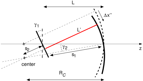
By using some basic geometry we see that the new cavity length is given by . We further find that
| (27) |
and
| (28) |
Thus we can write the new cavity length as
| (29) |
or for small angles:
| (30) |
This result shows a quadratic dependency on the mirror misalignment. The change in the cavity length yields a change in the phase of the circulating light. In the following we will refer to the term also as phase noise which implies some assumptions on the frequencies of the alignment fluctuations with respect to the cavity linewidth, see below.
To quantify the alignment noise coupling we can compute a limit on the fluctuation of one mirror with respect to a phase noise sensitivity. Due to the nature of the seismic isolation systems the alignment fluctuations of the core optical components in a gravitational wave detector have similar spectral distributions: the alignment fluctuations are largest at Fourier frequencies below a cut-off frequency (often 1 Hz) and decrease rapidly with increasing frequency. Thus the phase noise at a given frequency as a function of the quadratic coupling of alignment fluctuation as shown in (30) is dominated by the mix-terms between a low-frequency (quasi-static) misalignment and the fluctuations at . We therefore write the alignment fluctuations as a sum of a DC term and an AC term:
| (31) |
This yields for the phase noise at a given Fourier frequency :
| (32) |
This change in cavity length is equivalent to that of a mirror displacement of if the frequency of the alignment fluctuations are within the cavity linewidth . In general the frequencies of interest are largely outside the cavity bandwidth. However, the low frequency limit of the measurement band can be considered to be within the cavity linewidth (limits for third generation ground based detectors are expected to be between 1 Hz and 50 Hz). Alignment noise specification are of special interest at this lower bound because the alignment fluctuations fall steeply with increasing frequency. The following alignment noise limits will be computed for Fourier frequencies in the low frequency band of the detector sensitivity.
Commonly the alignment noise specifications are computed such that a certain amount of quasi-static misalignment is assumed, based on experience with suspension control systems, and then a limit for the high frequency fluctuations can be derived with respect to a given sensitivity limit. A typical value for the residual root mean square misalignment integrated over a band between 0 Hz to 10 Hz for future gravitational-wave detectors can be assumed to be nrad [16]. We consider the mirrors to be misaligned statically by and and the far mirror is rotating further with an amplitude of at frequency . This yields a phase noise of:
| (33) |
Equation 33 shows that the maximum phase noise is reached when , which yields:
| (34) |
If we take to be the (differential) phase noise in the arm cavities of a Michelson interferometer and we further assume a sensitivity goal for that Michelson of we can use (34) to compute a limit for , i.e. the alignment noise at the second mirrors. Using exemplary parameters for the cavity length and mirror curvature from the VIRGO interferometer [2], we obtain the following alignment noise limit:
| (35) |
In the following sections we will use the same method to compute limits on alignment fluctuations for cavities that employ gratings. In the presence of gratings we also need to know the displacement of the optical axis. In order to compute the lateral translation of the eigenmode with both mirrors misaligned we first compute the coordinate of the center of the sphere associated with the end mirror:
| (36) |
With this we can compute the coordinate of the point where the eigenmode touches the front mirror:
| (37) |
which gives a new coordinate for the eigenmode of
| (38) |
And for small angles
| (39) |
We find that the lateral displacement is linearly dependent on the misalignment angles. This displacement does not result in a dominant phase noise contribution when conventional mirrors are used but is shown in the next section to be critical when gratings are employed.
5.2 Two-port grating as coupling ’mirror’ into arm cavity
In this section we will compare the above results to those of a similar cavity with a grating as the input couplers (see Figure 2 bottom, left). We use the same parameters as above; i.e. the grating is flat and the end mirror is spherical. It should be clear that the cavity with a grating experiences exactly the same coupling of alignment into phase noise as computed for the two-mirror cavity. However, there is an additional coupling process through the transversal displacement of the eigenmode on the grating.
The displacement of the optical axis for a misalignment of the end mirror by can be approximated as:
| (40) |
With respect to the grating coordinate system we shall write:
| (41) |
As shown above, the translation of the beam on the grating will result in a variation of the optical path length during the refraction as:
| (42) |
Such change in phase corresponds to an apparent fluctuation in the cavity length of . From this we can compute, for example, new limits for the alignment noise of the second mirror. Assuming again a sensitivity goal of , VIRGO-like parameters and typical values for the grating parameters we can write:
| (43) |
which proves to be a much more stringent alignment requirement than the direct coupling mechanism of alignment into phase noise given in (35).
5.3 Three-port grating as coupling ’mirror’ into arm cavity
In the case of a three-port grating as the cavity input mirror with the cavity mode impinging on the grating at normal incidence the situation is a little different: Since the cavity mode does not experience refraction at the grating but rather a zero order reflection, a translation of the mode will not create an optical path length change within the cavity. However, the beams leaving or entering the cavity will experience exactly the same phase noise as described above. The main difference is that the limits in this case are relaxed by the finesse of the arm cavity. Hence, for a cavity with finesse and a three-port grating coupling mirror we can compute limits for the misalignment of the far mirror to be:
| (44) |
However, the presence of the grating will result also in more stringent requirements for the input beam jitter [16] which are beyond the scope of this article.
5.4 Four-port grating and beam splitters
When a four-port grating is used for a beam splitter (as shown in Figure 2) the outgoing beams are given by the interference between a zero-order and a first-order diffracted beam. Any translation of the grating or the incoming beams along their respective -axis results in phase noise in the first-order beams causing the interference to be directly affected by the translation. The effect is comparable to a translation of a standard beam splitter along its surface normal. If a four-port grating was used as a central beam splitter in a VIRGO-like optical layout any translation of the beams impinging on this beam splitter would be caused primarily by changes in the optical axes of the arm cavities as computed above. We can thus derive alignment specifications for the arm cavity mirrors, and again, the specifications are relaxed by the cavity finesse because the phase noise originates outside the arm cavities. In the example of the VIRGO interferometer this translates into the same alignment limits for the far mirror as given in Equation 44.
6 Conclusion
Diffraction gratings have been proposed as replacements of traditional mirrors and beam splitters for interferometric gravitational-wave detectors. However, so far only draft optical layouts have been published without an in-depth analysis of their noise performance. To our knowledge we have for the first time presented the effects of beam and grating alignment on the outgoing beam in a form required to estimate the sensitivity and performance of a long-baseline laser interferometer with reflective diffraction gratings as core optical elements. Diffraction gratings differ from traditional mirrors and beam splitters in several ways; in particular they reduce the symmetry between the interacting beams. Comparing ideal diffraction gratings with traditional, ideal mirrors and beam splitters shows that the reduced symmetry results in extra coupling of geometry changes of the grating or the incoming beam into alignment and phase changes of the outgoing beam. In particular, a displacement of the grating along the -axis (perpendicular to the grating normal and to the grating grooves, see Figure 3) introduces a periodic change of the optical path length while a displacement of the incoming beam along (perpendicular to the beam axis and to the grating grooves) introduces a continuous change of the optical path length. The optical path length change is proportional to the order of the diffracted beam, especially it is zero for the zeroth order.
The extra alignment changes are of the same magnitude and quality as the normal alignment effects. The additional coupling of a roll motion into beam misalignment probably requires a careful design of the suspension system of diffraction gratings. However, the additional coupling of beam alignment noise into phase noise at a grating results in much more stringent alignment specification for main interferometer components if a grating is used either as coupling mirror for arm cavities or as the main beam splitter. By analysing a simplified example, using VIRGO-like parameters for the optical system, we could show that the currently proposed draft topologies for the use of diffraction gratings would result in challenging requirements for the alignment of the optical components - the grating as well as the other main interferometer mirrors. Even considering the ongoing development of suspension systems [17] for the core optical elements of future gravitational-wave detectors, the all-reflective topologies discussed so far would very likely be limited by alignment noise. In order to benefit from advantages of diffraction gratings, these optical layouts of refractive interferometers must be designed carefully, and topologies with higher symmetry found, in order to minimise the alignment related phase noise. Furthermore, new suspension systems should be investigated, which could provide a reduction of alignment noise to the required level.
7 Acknowledgment
We thank S. Hild, R. Schilling, S. Chelkowski and M. Mantovani for useful discussions. A. F. would like to thank STFC for financial support of this work. We also thank the Deutsche Forschungsgemeinschaft (DFG) and the SFB TR7 for support. This document has been assigned the LIGO Laboratory document number LIGO-P070094-00-Z.
References
References
- [1] S. Hild and the LIGO Scientific Collaboration. The status of GEO 600. Classical and Quantum Gravity, 23:643, October 2006.
- [2] F. Acernese and the VIRGO Collaboration. The Virgo status. Classical and Quantum Gravity, 23:635, October 2006.
- [3] D. Sigg. Commissioning of LIGO detectors. Classical and Quantum Gravity, 21:409, March 2004.
- [4] R. Takahashi and the TAMA Collaboration. Status of TAMA300. Classical and Quantum Gravity, 21:403, March 2004.
- [5] R.W.P. Drever. Concepts for extending the ultimate sensitivity of interferometric gravitational wave detectors using non-transmissive optics with diffractive or holographic coupling. volume -, page 1401. Proceedings of the Seventh Marcel Grossman Meeting on recent developments in theoretical and experimental general relativity, gravitation, and relativistic field theories. Proceedings of the Meeting held at Stanford University, 24-30 July 1994, 1996.
- [6] R. Schnabel, A. Bunkowski, O. Burmeister, and K. Danzmann. Three-port beam splitters-combiners for interferomter applications. Opt. Lett., 31:658, 2006.
- [7] Ke-Xun Sun and Robert L. Byer. All-reflective michelson, sagnac, and fabry-perot interferometers based on grating beam splitters. Opt. Lett., 23:567, 1998.
- [8] A. Bunkowski, O. Burmeister, P. Beyersdorf, K. Danzmann, and R. Schnabel. Low-loss grating for coupling to a high-finesse cavity. Opt. Lett., 29:2342, 2004.
- [9] A. Bunkowski, O. Burmeister, T. Clausnitzer, E.-B. Kley, A. Tünnermann, K. Danzmann, and R. Schnabel. Optical characterization of ultrahigh diffraction efficiency gratings. Appl. Opt., 45(23):5795–5799, 2006.
- [10] R Nawrodt, A Zimmer, T Koettig, T Clausnitzer, A Bunkowski, E B Kley, R Schnabel, K Danzmann, S Nietzsche, W Vodel, A Tünnermann, and P Seidel. Mechanical q-factor measurements on a test mass with a structured surface. New Journal of Physics, 9(7):225, 2007.
- [11] S. Wise, V. Quetschke, A. J. Deshpande, G. Mueller, D. H. Reitze, D. B. Tanner, B. F. Whiting, Y. Chen, A. Tünnermann, E. Kley, and T. Clausnitzer. Phase Effects in the Diffraction of Light: Beyond the Grating Equation. Physical Review Letters, 95(1):013901, June 2005.
- [12] A. Bunkowski, O. Burmeister, K. Danzmann, and R. Schnabel. Input-output relations for a three-port grating coupled fabry-perot cavity. Opt. Lett, 30:1183, 2005.
- [13] A. Bunkowski, O. Burmeister, K. Danzmann, R. Schnabel, T. Clausnitzer, E.-B. Kley, and A. Tünnermann. Demonstration of three-port grating phase relations. Opt. Lett, 31:2384, 2006.
- [14] R. Barille, F. Frasconi, A. Freise, P. La Penna, M. Loupias, E. Majorana, J. Marque, A. Paoli, L. Paoli, P. Ruggi, and E. Tournefier. The pre-alignment of the virgo 3-km interferometer. Technical Report VIR-NOT-EGO-1390-271, VIRGO, 2004.
- [15] M. C. Rushford, W. A. Molander, J. D. Nissen, I. Jovanovic, J. A. Britten, and C. P. Barty. Diffraction grating eigenvector for translational and rotational motion. Optics Letters, 31:155–157, January 2006.
- [16] G. Mueller. Beam jitter coupling in advanced LIGO. Opt. Express, 13:7118–7132, September 2005.
- [17] N. A. Robertson et al. Seismic isolation and suspension systems for Advanced LIGO. In J. Hough and G. H. Sanders, editors, Gravitational Wave and Particle Astrophysics Detectors. Edited by Hough, James; Sanders, Gary H. Proceedings of the SPIE, Volume 5500, pp. 81-91 (2004)., volume 5500 of Presented at the Society of Photo-Optical Instrumentation Engineers (SPIE) Conference, pages 81–91, September 2004.