Transfer and teleportation of quantum states encoded in decoherence-free subspace
Abstract
Quantum state transfer and teleportation, with qubits encoded in internal states of the atoms in cavities, among spatially separated nodes of a quantum network in decoherence-free subspace are proposed, based on a cavity-assisted interaction by single-photon pulses. We show in details the implementation of a logic-qubit Hadamard gate and a two-logic-qubit conditional gate, and discuss the experimental feasibility of our scheme.
pacs:
03.67.Hk, 42.50.DvQuantum state transfer and teleportation are significant components in quantum information processing, especially for quantum network. As the confined atoms in cavity QED system are well suited for storing qubits in long-lived internal states, spatially separated cavities could be used to build a quantum network assisted by photons cirac ; photon ; cpf ; xue ; ng ; tr ; deng ; J . On the other hand, decoherence due to the inevitable interaction with environment destroys quantum coherence. So decoherence-free subspaces (DFSs) of Hilbert space has been introduced to protect against some errors due to environmental coupling with certain symmetry dfs0 ; dfs1 ; dfs2 . For example, Ref. dfs2 utilized two atoms to encode single-logic-qubit, i.e., , , which are robust to collective dephasing error caused by ambient magnetic fluctuation.
In this Brief Report, for the quantum state encoded in DFS mentioned above, we present implementation of single-logic-qubit Hadamard gate and two-logic-qubit conditional gate based on cavity-assisted interaction with single-photon pulses. Based on these gates, we will carry out the quantum state transfer and teleportation between two spatially separated nodes in a quantum network. Compared with previous related works, our proposal does not rely on the synchronous optical lattices xue in implementation of the single-logic-qubit Hadamard gate. In addition, auxiliary entangled photon pairs, as employed in ng , are unnecessary in our two-logic-qubit conditional gate. Moreover, for quantum state transfer, neither the entangled photon pairs tr nor the special time-symmetric wave packet of the photons cirac is necessary in our scheme. So our scheme could not only protect quantum information from some decoherence, but also reduce the experimental difficulty compared to the previous schemes cirac ; xue ; ng ; tr . Furthermore, in our scheme, each node of the quantum network in DFS has individual input port for photons to complete necessary operations, and different operational results can be distinguished by detecting output photons.
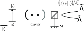
The main idea using cavity-assisted photon scattering to realize a controlled phase flip (CPF) between two atoms cpf ; xue ; ng ; tr ; deng , is sketched below. Suppose that two identical atoms, each of which has a three-level configuration, are well located in a high-finesse cavity. The levels and of the atom are resonantly coupled by the bare cavity mode with polarization or by the component of an input photon, while level is decoupled because of the large detuning, as shown in Fig. 1. If the duration of the input photon pulse is sufficiently long and the atom-cavity coupling is much stronger than both the cavity decay and spontaneous emission of the atomic state, the pulse in resonance with the bare cavity mode, i.e., the two atoms in the state , would yield the pulse shape almost unchanged but with a phase added when reflected by the cavity. On the contrary, if any of the two atoms is in the state , as the cavity mode is shifted by the resonance with the atom, the pulse will be reflected by the cavity with both its shape and phase unchanged cpf . Therefore, by reflecting a single-photon pulse with polarization, the two-atom controlled phase gate is available.
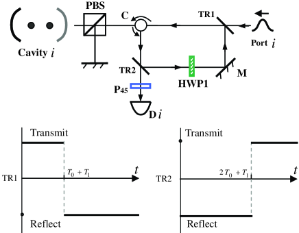
To carry out a quantum transfer and a teleportation in the DFS, we need to construct a Hadamard operation on the single-logic qubit and a conditional gate operation on the two-logic qubit. The operation is shown in Fig. 2 for the logic-qubit at arbitrary node (or, say, cavity ). The half-wave plate 1 (HWP1), with its axis at to the horizontal direction, rotates the photon polarization as . P45 is a polarizer projecting the polarization . TR is a device which can be controlled exactly as needed to transmit or reflect a photon tr , and the switching-time sequences of TR1 and TR2 are also given in Fig. 2.
Assume that the state of the logic-qubit in cavity is . The operation can be performed by following four steps. (1) A single-photon pulse in state is imported from port . It passes through TR1 and C, and then reaches the polarizing beamsplitter (PBS) and the cavity . Meanwhile, we perform a flip operation on the logic-qubit inside the cavity , i.e., whose function is to flip the logic-qubit deng , and thereby the state becomes after the photon pulse comes back from the cavity and the PBS. (2) Reflected by TR2, the photon pulse goes through HWP1, yielding the state . (3) After being reflected by M and TR1, the single-photon pulse arrives at PBS again. We need two NOT operations on atom 1, one before and another after the photon pulse is reflected by the cavity, i.e., the operation sequence . So we get to the state . (4) Finally, when the single-photon pulse passes TR2 and P45, the photon is detected by D, and thereby the logic-qubit inside the cavity is left in the state . The operation process above can be shown more specifically as follows,
| (1) |
So a click of D means the success of the Hadamard gate on the logic qubit. Otherwise, we have to repeat above steps from the very beginning with the single photon input and initial atomic state preparation. It is easy to check that Fig. 1 also works for to be . Compared with the previous operation of a single-logical-qubit Hadamard gate xue , our proposal needs neither the ancilla system to store information nor the optical lattices to transfer atoms synchronously across the cavity.
To ensure the success of above operations, we require the switching time sequences of TR to be implemented accurately tr . Actually, in addition to the time control sequences of TR1 and TR2 designed in Fig. 2, we have an alternative. Take TR1 for instance: Once the single-photon pulse from port has gone through TR1, we change the transmitting state of the TR1 into reflecting state without waiting for the time . The switching-time sequence designed for is general for arbitrary states of the single-logic qubit.

A two nodes controlled phase gate for logic-qubits encoded in a DFS, without using the entangle photon pairs as in ng , can be implemented with the aid of an additional channel shown by dashed gray lines in Fig. 3. HWP2, at an angle of to the horizontal direction, performs a Hadamard gate on the photon polarization states, i.e., , . is a controlled z (C-Z) phase- flip gate with subscripts and indicating the control and target logic-qubits in cavities and , respectively. Assume that the two logic-qubits are in superposition state, , where and are normalized constants. The operation is completed by following three steps. (1) A single-photon pulse in state is input from the port , passes through PBS, and reaches the cavity . We need to perform following operations , i.e., operation on the atom 2 in cavity before and after the single-photon pulse is reflected by the cavity . (2) Due to reflection of TR2, the single-photon pulse passes through HWP1 and goes into the additional channel connected to the node . (3) After going through HWP2 and reflected by TR3*, the single-photon pulse arrives at the PBS and then the cavity . As previously, we have to perform , i.e., the operation, on the atom 1 in the cavity before and after the single-photon pulse is reflected by the cavity . Then the single-photon pulse goes through and would be detected by D. The operation process above can be shown step by step as
| (2) |
If we get a click of D, the operation succeeds. The silence of D means failure and we must repeat above steps from the very beginning. Considering the symmetric operation for the two qubits gate, the operation can be done by a similar process to Eqs.(2), where the single-photon pulse is input from port , as shown in Fig. 3. The corresponding controlled-NOT(CNOT) operation for the logic qubits in a DFS is given by and . It should be mentioned that, the TR1* (or TR3* for node ), whose function is to connect spatially separated nodes, has no action during the single-logic-qubit Hadamard operation. So we can keep them always on in transmitting state during the time the operation is carried out in individual nodes.
The transfer of information in a quantum network is an important subject for quantum information processing cirac ; photon . Based on the operations investigated above, we realize below the information exchange between the th logic-qubit and the th logic-qubit , using following single-photon pulse sequence:
| (3) |
The corresponding process reads . Compared with previous work cirac , we do not need the special laser pulses with time-dependent Rabi frequency and laser phases to excite a time-symmetric wave packet of the photon from the sending node to the receiving node. In addition, we do not require a transfer channel made using auxiliary entangled photon pairs tr . More importantly, compared to cirac ; tr , our logic-qubits are encoded in DFS which is robust to collective dephasing error.
| Alice’s measurements | Bob’s operations |
|---|---|
| Nothing | |
Now we turn to a proposal for quantum state teleportation bennett for the logic qubits described above. Assume that we have three logic-qubits in states , and , respectively, with the former two belonging to Alice and the third to Bob. is an unknown state and would be teleported to Bob. Firstly, teleportation need entanglement between Alice’s second qubit and Bob’s qubit in a Bell state. We take for example. The Bell-style entanglement can be implemented by and operation for the initial state , i.e.,
| (4) |
The Bell state measurement in teleportation also uses and operations, i.e., a operation between and and an operation to . As a result, we get the final state . Following the operations shown in Table 1, we finish the teleportation of a quantum state from the logic-qubit to the logic-qubit .
From the schematic setup in Fig. 3 and the operations presented above, we can learn that the single-logical-qubit Hadamard operation and the two-logical-qubit conditional operation are coexisting in our scheme and could work independently by controlling the transmitting or reflecting state of the connecting devices TR1* and TR3*. This is very important for scalability of the quantum network.
Experimentally, the currently achieved technology of deterministic single-photon source hij provides potential support for our scheme. As 300,000 high-quality single photons could be generated continuously within 30 sec, a fast implementation of our scheme is available. Moreover, to fix two atoms in an optical cavity, we have to confine the atoms in optical lattices embedded in an optical cavity, and this has been achieved experimentally sauer . To confine each atom in a particular lattice, a more advanced technique is needed. Alternatively, we may consider an ion-trap-cavity combinatory setup with two charged atoms fixed by the trap potential and optically coupled by the cavity mode. A single Calcium ion has been successfully trapped in such a device blatt . The experimental extension to two ions satisfying Purcell condition would be in principle available in the near future.
In our scheme, if the duration for the photon pulse input in the cavity and the cavity decay rate satisfies , the basic operation is insensitive to both the atom-cavity coupling strength and the Lamb-Dicke localization. According to the numerical simulation cpf , if and the atom-cavity coupling is several times stronger than the dissipative factors of the system, the gate fidelity is almost unity. In terms of the numerical cpf and the experimental results J , a takes for . With the experimental numbers MHz, MHz, MHz J ; time , we may estimate the time for the logic-qubit operations and to be of the order of . In realistic experiments, however, we should pay attention to photon loss during the experiment and to the detector efficiency. Fortunately, as the different operational results in each step are distinguishable in our scheme, (for example, the single-logic-qubit operation in the th cavity is associated with a single-photon pulse input in port and the detector D, whereas the two-logic-qubit operation is relevant to the input port and the response of D), the successful detections of the single-photon pulses ensure the high fidelities of the gate operations. That implies that, as we discard the events without detector clicks, the errors due to photon loss can be completely removed, i.e., this is a repeat-until-success operations repeat . So, for our proposal, high-fidelity quantum gatings are possible even in the case of the photon loss p .
In summary, we have proposed the implementation of a single-logic-qubit Hadamard operation and a two-logic-qubit conditional gate, based on which we may carry out quantum state transfer and teleportation between spatially separated nodes of a quantum network in a DFS. As the cavity QED technique develops very quickly, we hope for more applications of the quantum logic operation in DFS regarding our scheme.
This work is partly supported by National Natural Science Foundation of China under Grant Nos. 10474118 and 60490280, by Hubei Provincial Funding for Distinguished Young Scholars, and partly by the National Fundamental Research Program of China under Grant No. 2005CB724502 and No. 2006CB921203.
References
- (1) J. I. Cirac, P. Zoller, H. J. Kimble and H. Mabuchi, Phys. Rev. Lett. 78, 3221 (1997).
- (2) Q. A. Turchette, C. J. Hood, W. Lange, H. Mabuchi, and H. J. Kimble, Phys. Rev. Lett. 75, 4710 (1995);M. Brune et al., Phys. Rev. Lett. 77, 4887 (1996); K. Mattle, H. Weinfurter, P. G. Kwiat, and A. Zeilinger, ibid. 76, 4656 (1996).
- (3) L.-M. Duan, B. Wang, and H. J. Kimble, Phys. Rev. A 72, 032333 (2005); L.-M. Duan and H. J. Kimble, Phys. Rev. Lett. 92, 127902 (2004);J. Cho and H.-W. Lee, ibid. 95, 160501 (2005); B. Wang and L.-M. Duan, Phys. Rev. A 72, 022320 (2005).
- (4) P. Xue and Y. F. Xiao, Phys. Rev. Lett. 97, 140501 (2006).
- (5) X.F. Zhou, Y.S. Zhang and G.C. Guo, Phys. Rev. A 71, 064302 (2005).
- (6) Z. J. Deng, M. Feng and K. L. Gao, Phys. Rev. A 75, 024302 (2007).
- (7) J. McKeever et al., Phys. Rev. Lett. 90, 133602 (2003); J. McKeever et al, Nature (London) 425, 268 (2003).
- (8) D. A. Lidar, D. Bacon, J. Kempe and K. B. Whaley, Phys. Rev. A 63, 022307 (2001); J. Kempe, D. Bacon, D. A. Lidar and K. B. Whaley, Phys. Rev. A 63, 042307 (2001).
- (9) A. Beige, D. Braun, B. Tregenna and P. L. Knight, Phys. Rev. Lett. 85, 1762 (2000); A. Beige, D. Braun, and P. L. Knight, New J. Phys. 2, 22 (2000); Paul G. Kwiat et al., Science 290, 498 (2000); D. Kielpinski et al., ibid. 291, 1013 (2001).
- (10) L.-M. Duan and G. C. Guo, Phys. Rev. Lett. 79, 1953 (1997); M. Feng, Phys. Rev. A 63, 052308 (2001); D. Kielpinski, C. Monroe, and D. J. Wineland, Nature (London) 417, 709 (2002).
- (11) L. M. Liang and C. Z. Li, Phys. Rev. A 72, 024303 (2005); Y. F. Xiao et al., ibid. 70, 042314 (2004).
- (12) C. H. Bennett et al, Phys. Rev. Lett. 70, 1895 (1993).
- (13) M. Hijlkema et al., Nature Phys. 3, 253 (2007).
- (14) J. A. Sauer et al, Phys. Rev. A 69, 051804(R) (2004).
- (15) A. B. Mundt et al, Phys. Rev. Lett. 89, 103001 (2002).
- (16) A. Boca et al, Phys. Rev. Lett. 93, 233603 (2004); Z. J. Deng, K. L. Gao and M. Feng, J. Phys. B 40, 351 (2007).
- (17) Y.L Lim, A. Beige and L.C. Kwek, Phys. Rev. Lett. 95, 030505 (2005).
- (18) L.-M. Duan and R. Raussendorf, Phys. Rev. Lett. 95, 080503 (2005).