Superlens imaging theory for anisotropic nanostructured metamaterials with broadband all-angle negative refraction
Abstract
We show that a metamaterial consisting of aligned metallic nanowires in a dielectric matrix has strongly anisotropic optical properties. For filling ratio , the composite medium shows two surface plasmon resonances (SPRs): the transverse and longitudinal SPR with wavelengths . For , the longitudinal SPR, the material exhibits , , relative to the nanowires axis, enabling the achievement of broadband all-angle negative refraction and superlens imaging. An imaging theory of superlens made of these media is established. High performance systems made with Au, Ag or Al nanowires in nanoporous templates are designed and predicted to work from the infrared up to ultraviolet frequencies.
pacs:
72.80.Tm,78.20.Ci,42.30.Wb,78.66.BzSince the demonstration of negative refraction (NR) Veselago at microwave frequencies Shelby , a variety of approaches have been described to observe the phenomenon at optical frequencies Shalaev07 . There are several reasons for the interest in NR, the most prominent application being the concept of perfect lens Pendry00 which can lead to sub-wavelength imaging beyond the diffraction limit. So far NR has been realized in periodic or quasiperiodic structures such as metamaterials Shelby and photonic crystals Notomi ; Luo ; Parimi04 .
As the frequency is increased to the optical spectrum, the structure size and the unit cell size shrink to nanometer dimensions. Important developments in nanofabrication do allow the fabrication of nanostructures down to 10 nm sizes over large areas. Using either top-down nanolithography or bottom-up self assembly, it is possible to fabricate aligned nanowires in dielectric matrices with large aspect ratios. For example, in alumina nanoporous templates Jessensky , the pore diameter can be modified between 10 to 200 nm and the thickness can be a few nanometers up to 160 m Lee . Typical sizes of the pore diameter of 10 nm, pore distance of 50 nm can be easily obtained. Au nanowires synthesized inside the template make a uniform array of vertical nanowires arranged parallel to each other Sander ; McMillian ; Menon .
In this paper we show that such aligned nanowire structures in dielectric matrices constitute a class of indefinite index media with strongly anisotropic optical properties that can be used to achieve broadband all-angle NR (AANR) and superlens imaging. We show that these anisotropic media will have two surface plasmon resonances (SPR): a longitudinal SPR and a transverse SPR. For wavelength larger than that of the longitudinal SPR, these media are negative index metamaterials and can be used for superlens imaging Pendry00 ; Lu05 in the frequency range from the deep-infrared up to the ultraviolet. NR and superlens imaging are possible due to the anisotropic optical properties. These structures do not need to be periodic. Disordered structures can also be used for NR. Example systems are designed and demonstrated.
We consider a metal with embedded in an ambient medium with positive . In the long wavelength limit, one has the Bruggeman’s effective medium theory (EMT) Aspnes ; Sihvola ; Mackay
| (1) |
Here is the metal filling ratio and is a measure of the aspect ratio. The solution is
| (2) |
with . The sign is chosen such that . For sphere inclusion, one has Aspnes . For slab inclusion, and for the effective permittivity perpendicular and parallel to the slabs, respectively.
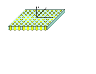
For cylinder inclusion with cylindrical axis in the -direction as shown in Fig. 1, one has
| (3) |
There exists a minimal filling ratio
| (4) |
such that for , . Also that if , . If one desires but , one should have so that . We note that for the modelling of real systems, the values of can be different from the ones we used note1 .
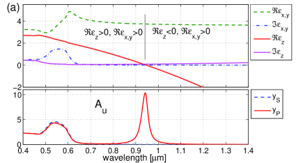
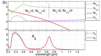
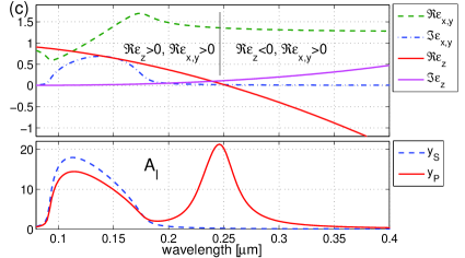
The physical meaning of is the following. At this filling ratio which also corresponds to a fixed frequency or wavelength since is dispersive, the composite medium has which gives strong absorption of the medium. This frequency corresponds to the so-called longitudinal SPR Yu ; Atkinson . For example for a Drude metal with and the plasmon wavelength, one has . Thus is very sensitive to the filling ratio and dielectric constant of the host medium. The increase of the filling ratio results in a blue-shift of the longitudinal SPR. The smaller the refractive index of the host medium, the shorter the longitudinal SPR . High absorption is also expected for frequency at the so-called transverse SPR, which is located around the surface plasmon wavelength () and has very weak dependence on the filling ratio. For a Drude metal, there is a frequency range with , such that and the medium shows strong absorption. Here and . For , one has .
For composite media with embedded Ag, Au, and Al nanowires, the effective permittivities and the absorption spectra are calculated and shown in Fig. 2. Here and are the reflection and transmission intensities of waves through a slab. The optical constants are taken from Ref. Weaver and fitted with polynomials. The absorption spectra clearly show the longitudinal SPRs for the -polarized waves.
When the metamaterial has and , this so-called indefinite medium Smith03 has unusual wave refraction phenomena and can be used for NR and superlens imaging for incident waves along the nanowire axis. We consider a slab of such medium whose surface is along the -axis and surface normal is along the -axis as shown in Fig. 3(b). We assume the relative permeability is of unity. For the -polarization with the magnetic field in the -direction and the electric field in the -plane, the dispersion is . Here the wave number in free space. When and , the equi-frequency surface (EFS) is hyperbolic instead of elliptic as shown in Fig. 3(a). For this medium, it is more meaningful to discuss the energy flow. The group velocity refraction is governed by Lu05
| (5) |
Here is the angle for the incident group velocity and is that for the refracted group velocity (see Fig. 3(b)). The material property is defined and evaluated as Lu05
| (6) |
Here . One has for all propagating waves, thus AANR Luo can be realized in this medium. The group refractive index is related to through . One has . For small the EFS can be approximated elliptically by with and .
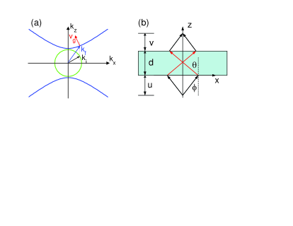
When is constant, then the phase across the lens is stationary and an image will be formed without aberration. Here , , and obey the equation (Fig. 3(b)). This is the lens equation for a generalized superlens. In this case the refractive index is angle-dependent, and one can achieve “perfect focusing” without an optical axis, as discussed in Ref. Lu05 . Note that the Veselago lens has , where the EFS is circular.
In the present anisotropic metamaterial, is angle-dependent and not a constant, because the EFS is hyperbolic and not elliptic Lu05 ; hence the lens has caustics, and the image is not “perfect”. Nevertheless, a high quality image can be formed by the lens with and . Furthermore, though the nonlocal effect Pokrovsky02 ; Belov03 ; Silveirinha06 ; Simovski07 ; Elser on effective permittivity indicates the limitation of Bruggeman’s EMT, it will render the EFS to be more elliptic than hyperbolic, thus can reduce the caustics.
The composite medium with cylinder inclusion can be used for NR and superlens imaging in three-dimensional free space for frequencies below the surface plasmon frequency. These metamaterials do not support surface waves. The enhancement of subwavelength imaging resolution is still possible Ono ; Silveirinha07 ; Shvets07 . If the lens is curved, one may be able to use it as a magnifying hyperlens Jacob ; Engheta06 . The currently studied multilayered structures Jacob ; Engheta06 ; Liu07 ; Shin ; Fan ; Pendry06 ; Hoffman for NR, superlens, and hyperlens are two-dimensional reductions of these structures. The filling ratio is special for multilayered metal-dielectric structures. At this filling ratio, and will always have the opposite signs. This has been utilized to realize magnifying hyperlens Jacob ; Engheta06 ; Liu07 . Naturally available anisotropic dielectric crystals may be used to achieve NR ZhangY but can not be used for superlens imaging.
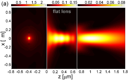
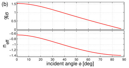
Anisotropic metamaterials with embedded Au, Ag, Al nanowires can be used for superlens imaging in the infrared, visible, and ultraviolet, respectively. For example for Al at nm, Weaver , a 10% filling ratio of Al nanowires in air gives and . A lens made of a flat slab of such medium has and can have a maximum thickness 11.9 m. The imaging effect of a point source by such a superlens is shown in Fig. 4(a). The angle-dependent lens property as shown in Fig. 4(b) leads to the presence of caustics which can be reduced if multiple lenses are used.
For the propagating waves within the plane, NR and superlens imaging can be realized in a finite slab of such an anisotropic medium. In this case for the -polarized waves, one has . For , , a free-suspending slab will support guided waves in the plane if and . These guided waves are backward waves with . In this geometry, surface waves can be formed which can lead to subwavelength imaging resolution. We point out that there is no need to sandwich this medium by perfect conductor waveguide plates as considered in Ref. Narimanov .
For the -polarization, the medium with cylinder inclusion is isotropic with positive effective permittivity. The dispersion is given by . No NR can be realized for this polarization.
There are two strategies to realize and depending on the wavelength or . Clearly sphere inclusion can not while the cylinder or slab inclusion will lead us to the desired anisotropy. For , the cylinder axis should be along the -axis which we have discussed in this paper. The slab inclusion must be realized as a metallic grating as in Ref. Fan . In this case one has and . Though loss is low in , NR is limitted to the -plane. We point out that the EMT theory gives a very simple explanation for the broadband AANR in the metallic grating Fan . Furthermore, the EMT is more accurate than the coupled-wave theory used in Ref. Fan . We also point out that our numerical simulations indicate that AANR does not require the metallic grating to be periodic.
For , indefinite medium can be realized if the cylinder axis is in the -plane for the cylinder inclusion. If the cylinder axis is along the -axis, one has and . For these wavelengths , one should have , high loss will be expected for . However the slab inclusion which is examplified by the multilayered metal-dielectric structures considered in Ref. Shin ; Pendry06 ; Hoffman , will have and for with low loss. For these structures Shin ; Pendry06 ; Hoffman , Bruggeman’s EMT may not be very precise to calculate the effective permittivity, but our imaging theory predicts that they are able to focus.
In summary, we have established an imaging theory of superlens made of nanoporous dielectric templates embedded with metallic nanowires with strong optical anisotropy. The effective permittivity of these media is obtained by Bruggeman’s EMT. Our theory is successfully used to give simple explanation of recent predictions of NR and superlens focusing in multilayered Fan ; Shin ; Pendry06 ; Hoffman and 2D structures Ono ; Silveirinha07 . For frequencies lower than the longitudinal SPR frequency, these media are indefinite media Smith03 . The existence of and is manifested by the fact that there is a band cutoff for the TM modes and no band cutoff for the TE modes of 2D metal-dielectric photonic crystals. The homogenization note1 ; HuX including the nonlocal effect Pokrovsky02 ; Belov03 ; Silveirinha06 ; Simovski07 ; Elser of 2D photonic crystals provides direct and more accurate ways to calculate the effective indices beyond EMT. Unlike resonant metamaterials which are sensitive to disorder Gorkunov , these nanowire media has large tolerance on disorder. These extremely anisotropic metamaterials are broadband and can be used for NR, superlens, and hyperlens applications in 3D for frequencies from infrared up to ultraviolet.
We thank L. Menon, D. Casse and R. Banyal for useful discussions. This work was supported by the Air Force Research Laboratories, Hanscom through FA8718-06-C-0045 and the National Science Foundation through PHY-0457002.
References
- (1) V. G. Veselago, Sov. Phys. Usp. 10, 509 (1968).
- (2) R. A. Shelby, D. R. Smith, and S. Shultz, Science 292, 77 (2001).
- (3) V. M. Shalaev, Nat. Photon. 1, 41 (2007).
- (4) J. B. Pendry, Phys. Rev. Lett. 85, 3966 (2000).
- (5) M. Notomi, Phys. Rev. B 62, 10696 (2000).
- (6) C. Luo, S. G. Johnson, J. D. Joannopoulos, and J. B. Pendry, Phys. Rev. B 65, 201104 (2002).
- (7) P. V. Parimi et al., Phys. Rev. Lett. 92, 127401 (2004); P. V. Parimi at al., Nature 426, 404 (2003).
- (8) O. Jessensky, F. Müller, and U. Gösele, Appl. Phys. Lett. 72, 1173 (1998).
- (9) W. Lee et al., Nat. Mat. 5, 741 (2006).
- (10) M. S. Sander and L.-S. Tan, Adv. Func. Mat. 13, 393 (2003); O. Rabin et al., Adv. Func. Mat. 13, 631 (2003).
- (11) B. G. McMillian et al., Appl. Phys. Lett. 86, 211912 (2005).
- (12) L. Menon et al., preprint (2007).
- (13) W. T. Lu and S. Sridhar, Opt. Exp. 13, 10673 (2005).
- (14) D. E. Aspnes, Am. J. Phys. 50, 704 (1982).
- (15) A. Sihvola, Electromagnetic mixing formulas and applications, Institute of Electrical Engineers, London (1999).
- (16) T. G. Mackay and A. Lakhtakia, Opt. Comm. 234, 35 (2004).
- (17) The homogenization of 2D photonic crystals gives and for and , respectively. There is no much difference in our subsequent discussions if more accurate expression is used. For homogenization of photonic crystals, see P. Halevi, A. A. Krokhin, and J. Arriaga, Phys. Rev. Lett. 82, 719 (1999); ibid. 86, 3211 (2001); A. A. Krokhin and E. Reyes, ibid. 93, 023904 (2004).
- (18) Y.-Y. Yu et al., J. Phys. Chem. B 101, 6661 (1997).
- (19) R. Atkinson et al., Phys. Rev. B 73, 235402 (2006).
- (20) J. H. Weaver et al., Optical properties of metals, Fachinformationszentrum, Karlsruhe, Germany (1981).
- (21) D. R. Smith and D. Schurig, Phys. Rev. Lett. 90, 077405 (2003); D. R. Smith, P. Kolinko, and D. Schurig, J. Opt. Soc. Am. B 21, 1032 (2004).
- (22) A. L. Pokrovsky and A. L. Efros, Phys. Rev. B 65, 045110 (2002).
- (23) P. A. Belov et al., Phys. Rev. B 67, 113103 (2003); P. A. Belov and C. R. Simovski, Phys. Rev. E 72, 026615 (2005).
- (24) M. G. Silveirinha, Phys. Rev. E 73, 046612 (2006).
- (25) C. R. Simovski and S. A. Tretyakov, Phys. Rev. B 75, 195111 (2007).
- (26) J. Elser et al., Appl. Phys. Lett. 90, 191109 (2007).
- (27) A. Ono and S. Kawata, Phys. Rev. Lett. 95, 267407 (2005).
- (28) M. G. Silveirinha, P. A. Belov, and S. R. Simovski, Phys. Rev. B 75, 035108 (2007).
- (29) G. Shvets, S. Trendafilov, J. B. Pendry, and A. Sarychev, Phys. Rev. Lett. 99, 053903 (2007).
- (30) Z. Jacob, L. V. Alekseyev, and E. Narimanov, Opt. Exp. 14, 8247 (2006).
- (31) A. Salandrino and N. Engheta, Phys. Rev. B 74, 075103 (2006).
- (32) Z. Liu et al., Science 315, 1686 (2007); I. I. Smolyaninov, Y.-J. Hung, and C. C. Davis, Science 315, 1699 (2007).
- (33) X. Fan et al., Phys. Rev. Lett. 97, 073901 (2006).
- (34) H. Shin and S. Fan, Appl. Phys. Lett. 89, 151102 (2006).
- (35) B. Wood, J. B. Pendry, and D. P. Tsai, Phys. Rev. B 74, 115116 (2006).
- (36) A. J. Hoffman et al., Nat. Mat., doi:10.1038/nmat2033.
- (37) Y. Zhang, B. Fluegel, and A. Mascarenhas, Phys. Rev. Lett. 91, 157404 (2003).
- (38) V. A. Podolskiy and E. Narimanov, Phys. Rev. B 71, 201101(R) (2005).
- (39) X. Hu et al., Phys. Rev. Lett. 96 223901 (2006).
- (40) M. V. Gorkunov et al., Phys. Rev. E 73, 056605 (2006).