Three-dimensional transformation for point rotation coordinate frames.
Abstract
We consider the transformation for the point rotation frames with the angle, spatial coordinate along the axis of rotation and time as variables. The problem arises when light, propagating through 3-fold electrooptical crystal, is modulated by the circularly polarized electromagnetic wave traveling along the optical axis of the crystal. With help of the transformation we show that such a wave cannot produce an extra optical frequency shift discussed earlier. In contrast to that the modulation by the rotating spatially invariable electric field produces the shift. The formal change to this case may be carried out by reducing the velocity of the traveling wave to zero. Some properties of the three-dimensional transformation are discussed.
pacs:
42.50.Xa, 03.65.Ta, 06.20.Jr, 06.30.GvI Introduction
Recently the general linear two-dimensional transformation for point rotation coordinate frames was considered jop . A distinguishing feature of the frame, in contrast to the Cartesian one, is the existence of the rotation axis at every point. The frame coordinates are an angle and time; the frequency of rotation is a parameter. The concept of the frame originates from the optical indicatrix (index ellipsoid) Nye ,Kam . Rotation of the optical indicatrix arises in three-fold electrooptical crystals under the action an rotating electric field applied perpendicular to the optical axis sm . Any rotating field also has the axis of rotation at every point. In this regard the point rotation frame is more adequate for the description of such fields than the Cartesian frame.
The consideration is motivated by necessity to know the frequency superposition law. The law is a consequence of the transformation and used for the description of the single-sideband modulation of light in electrooptical crystals sm ,jpc . The description is based on an approach connected with the transition to the frame with the resting indicatrix sm . The approach is shortly described below.
Consider a plane circularly polarized light wave propagating through the crystal with the rotating indicatrix. Transit to a frame with the resting indicatrix. The frequency of the wave is changed in correspondence with the law. If the amplitude of the modulating electric field equals the half-wave value then at the crystal output the circular polarization of the wave is reversed. After the transition to the initial frame the frequency shift is doubled. If the law is linear one then the shift equals the frequency of the modulating electric field (for the Pockels crystals). In the opposite case there must be an extra optical frequency shift. The linear law follows from the Galilean transformation which is postulated a priori.
In the general transformation the reverse frequency, i.e., the frequency of the first frame relative to the second one, is a function of the direct frequency. However both the frequencies are assumed to be symmetric. It means that the direct frequency is the same function of the reverse frequency. Using symmetry of the frame coordinates it was shown that three different types of the transformation are possible. The first type is a generalization of the Lorentz transformation. The second and third types are principally different and possess unusual properties, in particular, an uncertainty of the time determination. In Ref. jop an experiment for testing the second type of transformation was described with the modulation by the rotating spatially invariable electric field. Such a modulation corresponds to two-dimensional transformation.
The point rotation frames have no transverse coordinates and, therefore, they are not compatible with the Cartesian frames. However a coordinate along the axis of rotation can be used as the spatial coordinate.
In this paper we consider three-dimensional transformation for the point rotation frames with such a coordinate. For the point rotation frames we have no a principle, like the relativity principle, for obtaining the exact form of the transformation. Instead we use some symmetry considerations and the expansion of the transformation parameters in power series in terms of the direct and reverse frequency. As it was assumed in jop the characteristic time inherent in the transformation is about ”nuclear time” of the order of . The time is defined as the size of proton divided by the speed of light. Therefore the normalized frequency in the optical range is about and we can restrict the consideration to the first terms of the expansion. Moreover we assume that parameters connected with the spatial coordinate in the first approximation correspond values in the Lorentz transformation.
II Rotation of the optical indicatrix in 3-fold crystals.
It is well known that propagation of plane optical waves along the optical axis of 3-fold crystals is described by the section of the indicatrix perpendicular to the optical axis Nye ,Kam
| (1) |
where is the ordinary refractive index, is the applied electric field, are electrooptical coefficients Nye .
Using rotation around the optical axis , we reduce section (1) to the principal axes
| (2) |
where the refractive indices are given by
| (3) |
We consider the rotation of the optical indicatrix in two important cases. In the first one the applied electric field rotates around the optical axis but spatially is invariable: where is the frequency of the electric field. This is achieved by applying a electric field to the system of electrode pairs on the side faces of crystal. The rotation is provided by the corresponding phase shift for every pair jpc ,pat . The first case corresponds to infinitely large velocity or infinitely small length of crystal. Alternatively the time-transit problem must be taken into account.
In the second case the rotation is created by a powerful traveling circularly polarized electromagnetic wave with where is the propagation constant, the angle The optical indicatrix not only rotates but also moves with the velocity . In the second case the phase matching between the modulating and modulated wave is necessary.
The difference do not depend on time. If the phase retardation between two light components along the principal axes of the indicatrix after passing through the crystal equals , i.e., if then the crystal is equivalent to the rotating (or rotating and moving) half-wave plate. Here is the light wavelength, is the crystal length.
III Two-dimensional transformation
The general linear transformation for the transition from one frame to another may be written as follows jop
| (4) |
where is an angle (the angle between the electric vector of a plane circularly polarized light wave and an axis in the first frame), is time, is the frequency of second frame relative to first one, tilde corresponds to the reverse transformation. It is obvious that (4) turns out into the reverse transformation if variables with tilde change to variables without tilde and vice versa.
The functions and remain indeterminate except the condition at small , namely, if . Moreover if then Using new variables and both the equations may be rewritten in a symmetric form
| (5) |
where is a function with the condition , is a parameter. It is assumed that and have opposite signs therefore is always negative.
In jop it was found that, because of symmetry of and and the condition (5), the types of the transformation are defined by the equation
| (6) |
where is a dimensional constant.
Three type of solutions of Eq. (6) exist. First type is exact solution . The transformation (4) for the solution of the first type is a generalization of the Lorentz transformation.
The second type of solutions may be presented as series
| (7) |
where are constants, is a real negative root of the equation . For multiple roots the first term of expansion (7) is proportional to , where is multipleness of the root, with corresponding changes in next terms; in this paper we consider the most important case with . The third type is a supplement to the second type and corresponds to complex roots.
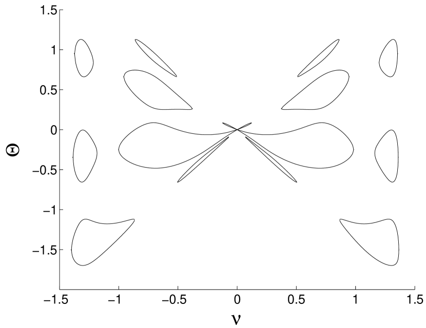
Examples of solutions of the second and third types are shown in Fig. 1. The examples represent the function for where is a polynomial of power with positive coefficients. For such polynomials solutions of Eq. (6) exist only for negative . The solutions of the second type cross each other at the point , others are solutions of the third type. The constant . Increasing this constant leads to the increase of asymmetry between the right and left part of the figure. Obviously the examples are far of exhausting all possibilities.
The expansion of in power series in cannot correspond to the solution (7). Such a correspondence is possible if the expansion has the form
| (8) |
where for In this case we do not miss the second and third types of solutions. Unfortunately in Ref. jop the value was used for Therefore the mistaken conclusion was made about asymmetry of the extra optical frequency shift by reversing of the electric field rotation. However the schematic of the experiment proposed in the paper jop allows to measure as asymmetric as symmetric shifts.
The transformation sm for the solution of the second type possesses an unusual property. For one follows from Eq. (7) . In this limit Eq. (4) is
| (9) |
The limit corresponds to the transformation ”into itself”. This result is interpreted as uncertainty of the time determination jop . Indeed, different ways are possible to come in the point (0,0) along one closed curve in Fig. 1.
Normalizing we arrive to the case . It is known that the Galilean as well as the Lorentz transformation is invariant under the sign change of both the velocity and time. Here we extend this principle to the transformation (4) and assume that the normalized transformation (4) is invariant under the change . It means that or in the expansion (8) coefficients and with odd and even respectively are equal zero.
In jop it was shown that the extra frequency shift at the crystal output may be measured only for the second type of solutions. In the first approximation the shift doesn’t depend on , i.e., such a shift may be produced by the usual half-wave plate. It, however, doesn’t mean that the shift could be doubled by passing the second modulator or the half-wave plate. In this case the polarization of the wave would turn back to its initial state and the extra shift would disappear.
IV Three-dimensional transformation
The transformation in the 3-dimensional case may be written in the following general form
| (10) | |||||
where is defined as in Section II, z is the coordinate along the axis of rotation, is the velocity of the second frame (the moving and rotating optical indicatrix) relative to the first one, all parameters are functions of For definiteness we assume that the right-hand polarized light, propagating in the positive direction of the z-axis, has positive The terms and describe the velocity and frequency dismatch between the modulating and modulated wave. Note that using the transformation (10) in another form, with the frequency and the velocity leads to erroneous results.
Using Eq. (10) we may find the output frequency in the experiment of Ref. jop . Let and to be the frequency and velocity of the light wave in the first frame. If the optical frequency in the second frame changes the sign then the output frequency in the initial frame is
| (11) |
where .
Now we assume that since is the velocity of rectilinear move, and normalize the transformation so that :
We assume that Eq. (10) is invariant under the change In this case whereas other parameters with the tilde equals to that without the tilde.
Using the reverse transformation, we obtain a system of five independent equations for seven parameters of Eq. (10). Expressing the parameters in the terms of we find
| (12) | |||||
| (13) | |||||
| (14) | |||||
| (15) |
Expand in power series in . It is reasonable to assume that coefficients of the expansion are even functions of
| (16) | |||||
| (17) |
In the limiting case at the parameter must be bounded therefore Moreover must be equal the corresponding Lorentz value: where , where is the speed of light in crystal. Using the values we obtain in the first approximation
| (18) | |||||
| (19) | |||||
| (20) | |||||
| (21) |
With these definitions the transformation Eq. (10) is
| (22) | |||||
| (23) | |||||
| (24) |
In the condition of the phase matching the reverse velocity must have physically acceptable values. From this requirement one follows that may be presented in the form where is a function, equals the introduced above characteristic time .
Using Eq. (11) we obtain for two cases and respectively
| (25) |
where we neglected small terms with in the first expression. The output frequency for coincides with the value calculated for the two-dimensional case. For the extra shift vanishes. Note that this result coincides for both the normalized and non-normalized transformation.
V Conclusion
We have considered the three-dimensional transformation for the point rotation frames in two important cases. In spite the fact that there is no a general physical principle, the transformation may be defined with help of some symmetry considerations and the expansion of parameters in terms of the frequency. A surprising result is the absence of the extra shift in the case of the modulation by traveling electromagnetic wave in condition of the phase matching.
However the main question about the existence of the extra shift in reality remains to be open. Some arguments in favour of the positive answer on this question are below.
The optical indicatrix as a coordinate frame have been used for more than hundred years. The Galilean transformation for such a rotating frames seems unacceptable since fields with infinitely large frequencies are not known in physics. The Lorentz transformation seems too simple because it have only one limiting frequency. In contrast to that the transformation corresponding to the solutions of the second and third type possesses a variety possibilities. The arguments in some extend confirm the necessity to perform measurements of the proposed extra shift and the characteristic time.
References
- (1) B. V. Gisin, Journal of Physics A 40, 1341-1347 (2007).
- (2) J. F. Nye, Physical Properties of Crystals (University Press, London, 1964).
- (3) I. P. Kaminov, An Introduction to Electro-optic Devices (Academic Press, New York, 1974).
- (4) C. F. Buhrer, D. H. Baird, and E. M. Conwell, Appl. Phys. Lett. 1, 46 (1962).
- (5) J. P. Campbell and W. H. Steier, IEEE J. Quantum Electron. QE-7, 450 (1971).
- (6) D.H.Baird and C. F. Buhrer, Single-Sideband Light Modulator (U.S. Patent 3204104, 1965).