CdZnTe room-temperature semiconductor operation in liquid scintillator
Abstract
We demonstrate the first operation of CdZnTe room-temperature detectors in a liquid scintillator environment. This work follows conceptually the Heusser-type detector method of operating HPGe detectors in liquid nitrogen and liquid argon but instead for a far more practical room-temperature ensemble with the aim of achieving ultra-low background levels for radiation detection.
pacs:
29.40.-nI Introduction
The motivation to research CdZnTe (CZT) detectors originates from participation in the COBRA experiment cobra , a proposed massive (several hundred kg) array of CZT crystals for double-beta decay research review . Taking into account a typical mass of just a few grams for each crystal, several tens of thousands of crystals will eventually have to be operated reliably over several years at an extremely low level of background, under counts per keV, kg and year in the signal region.
A relatively new detector concept to achieve such extremes of low background levels for semiconductor detectors has been proposed by Heusser heusser and later applied to large-scale double-beta decay projects genius gerda . Initially such a Heusser-type detector would use a passive but ultra-clean environment like liquid nitrogen to cool and shield HPGe detectors. Recently, the immersion of HPGe’s in an active (scintillating) medium such as liquid argon has become more attractive gerda2 .
In this work, we demonstrate that CdZnTe room-temperature semiconductor detectors also offer the option to be operated as a Heusser-type detector, in liquid scintillator, in order to achieve ultra-low background levels for double-beta decay. Clearly, the possibility to operate a room-temperature setup significantly simplifies the arrangement of a large number of detector crystals in a tank and should reduce overall costs. The great potential for extreme low background operation of liquid scintillators alone has already been shown, for example, in the Borexino and Kamland experiments borex , kamland .
II Experiment
Our test setup is simple but sufficient for a proof-of-principle in a series of planned experiments which are in progress. The first step was to identify suitable liquid scintillator cocktails, i.e. mixtures that would permit operation of electronics and high-voltage devices immersed within. No selection with reference to optical and scintillating properties has been made at this stage.
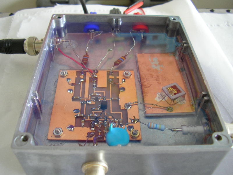
Crystals and preamplifier are housed together in a standard diecast enclosure featuring connectors for preamplifier power, BNC output and High-voltage input (see Fig. 1). A single HV-power supply (Ortec 659, NIM module) delivers both polarities up to 5kV. Two linear DC power supplies deliver V to the preamplifier. The output signal is connected directly to the data acquisition system (DAQ) using a 50 BNC cable (RG58). The DAQ consists of a 100 MHz sampling digital oscilloscope in a 3U PXI module from National Instruments (NI PXI-5112) mounted in a PXI crate (NI PXI-1042) and is controlled by an embedded controller PC (NI PXI-8186) running custom-made LabView software for digital pulse acquisition. Pulses are streamed directly to disk in binary format for maximum sampling speed when using radioactive sources for detector calibration.
The preamplifier is not a charge-sensitive amplification system but a custom-made voltage amplifier. The motivation to try this type initially, was to learn more about signal formation in the semiconductor, i.e. specialise the analysis and measurement to pulse-shape, in contrast to pulse-height. For a detailed discussion and circuit diagram, see detpaper .
Three coplanar grid detectors have been modified to work as Frisch collar detectors collar . All three are 1 cm cubes with gold-plated electrodes, a full-area cathode and a coplanar grid anode structure. Five faces (not the cathode face) are covered with insulating paint. Since we were not interested in operating the grid, paint covering the anode was partly removed (it dissolves easily in ethanol) and this area was used to contact the anode with a wire attached by a generous drop of silver conductive paint. The preamplifier is AC-coupled to the crystal anode which is biased positively by the HV-power supply. The cathode is kept at ground potential.
For the Frisch collar operation, each crystal was wrapped in two layers of thin teflon tape, covering the full height, leaving out anode and cathode, similar to devices fabricated in collar . The teflon layer was then wrapped in a metal foil (aluminium kitchen foil worked best for us) and the foil attached via a small ’lip’ to the cathode (using silver conductive paint). A crystal prepared thus was then mounted for operation on a ground plane. We used a small copper-clad piece of printed-circuit board connected to the preamplifier ground, see Fig. 1.
We note that with respect to low background operation, some materials listed above are not ideal, but can be replaced. The conducting foil could be high-purity, thin copper foil, and the crystals could be contacted properly, either by bonding or press-contact, again with a clean metal like copper, for example. Another advantage of Frisch-collar detectors would be that they can be mounted in a tightly packed array since physical contact of the metal shields around crystals would be possible (all share a common ground).
The metal foil height determines the performance of the Frisch collar detector collar . We achieved best performance with 9 mm - 9.5 mm foil height. Any higher shield results in stability problems when biasing the anode since the grounded shield appears to be too close, particularly at the cube corners. Again, for more details we refer to detpaper .
One major condition on the liquid scintillators was to respect health and safety rules directly from the start, easing any potential practical application. Fortunately, this is relatively straightforward since the advent of ’safe’ cocktails with low or no toxicity and no fire hazard. These types of scintillators are commercially available from various companies. Our first collection of scintillators was purchased from Perkin Elmer Life and Analytical Sciences perkin and National Diagnostics national . As stated above, an assessment of optical and scintillating properties for these liquids is work-in-progress (for results on some liquids, see majewski ). We identified four mixtures, each based on a different solvent, which are viable, see Tab. 1. We noticed that these viable cocktails all seem to share a characteristic in common, namely that, according to their manufacturers, they each specifically “target organic samples”, i.e. non-polar materials would be dissolved in the scintillator and measured in typical life-science applications. It is assumed that a low capacity of the cocktail to dissolve water as the primary example of a polar sample material improves the resistivity of the liquid.
III Results
Details of our data analysis procedure can be found in detpaper . It is explained there how we achieved an energy resolution (FWHM) of 1.9% at the Cs-line (662 keV) for one of our Frisch-collar detectors (Det #1) and just above 2% for the other two crystals. In this context it is interesting to note that subsequently, we dedicated Det #1 for the liquid scintillator project, hence all results presented here can be seen as a follow-up of detpaper using the same detector.
The first remarkable change of properties occured after just a few days immersion in the first liquid (Optiscint Hisafe). As was mentioned briefly in detpaper , the highest stable bias our detector could sustain at that moment in time was 1kV. Measurements at higher bias showed increasing rates of spurious pulses and deterioration of energy resolution. In liquid scintillator however, the stability of detector operation improved to a degree such that the stable operating bias was increased to 1.2kV with improved energy resolution and total absence of spurious pulses. This statement is valid for all scintillators tested and a collection of results can be seen in Tab. 1. Note that except for the Ecoscint liquid, all results improve on the energy resolution obtained in air (1.9%, see above and detpaper ), even if only slightly.
| Scintillator | Solvent | FWHM [%] |
|---|---|---|
| Cocktail name | (at 1200 Volt bias) | |
| EcoScint O | PXE (Phenylxylylethane) | 2.3 |
| Optiscint Hisafe | DIN (Di-isopropylnaphtalene) | 1.8 |
| Mineral Oil | 1.8 | |
| Opti-Fluor O | LAB (Linear alkyl benzene) | 1.75 |
A second observation can be reported at this point, which might become crucial for any low background operation of CdZnTe crystals in liquid scintillator. Encouraged by the stability and performance benefits of operating the detectors in liquid scintillator, another test series was started. This time, the protective (and unfortunately rather radioactive cobra ) paint on two crystals was removed by wiping with soft tissue and pure ethanol. Subsequently, as Frisch collar detectors in air, it was confirmed that the crystals would not take high-voltage bias beyond 400V without increased leakage current and an increasing rate of spurious pulses. A subsequent immersion in the selected liquid scintillator (based on energy resolution performance, see Tab. 1), Opti-Fluor O, for this long-term test, however, shows a remarkable recovery of the CdZnTe. After 24 hours, the detector (Det #1) takes up to a 1kV bias and the following energy resolutions were obtained (at the Cs-137 line, 662 keV, energy resolution given as relative FWHM): at 800V bias, 2.1%, at 900V, 1.9% and at 1kV, 2.0%. After another full day in the scintillator, the detector takes the full 1.5kV bias and shows stable and consistent energy resolutions: at 800V, 2.2% and at bias values between 900V and 1.5kV: 1.9% - 2.0%.
IV Conclusion
We have demonstrated that a room-temperature Heusser-type detector made from CdZnTe semiconductors, immersed in a safe liquid scintillator cocktail is a viable concept. Such a detector has the potential to achieve in a more practical and cost-effective way what cryogenic versions gerda set out to achieve, i.e. a large mass, ultra-low background experiment to measure rare events like double-beta decay. Additionally, prospects for low background operation of CdZnTe crystals have been improved by demonstrating a stable operation of clean, non-coated crystals directly in the insulating liquid scintillator. Long-term tests, assessments of optical properties and collection of further suitable liquid scintillators is work in progress.
Acknowledgements.
We wish to thank our collaborators on the COBRA project for providing the CZT crystals which were used in this study.References
- (1) K. Zuber, Phys. Lett. B519, 1 (2001); T. Bloxham et al., COBRA collaboration, Phys. Rev. C76, 025501 (2007)
- (2) F.T. Avignone, S.R. Elliott and J. Engel, Preprint http://uk.arxiv.org/abs/0708.1033v1; invited submission to Rev. Mod. Phys. (2007)
- (3) G. Heusser, Ann. Rev. Nucl. Part. Sci. 45, 543 (1995)
- (4) J. Hellmig and H.V. Klapdor-Kleingrothaus, Z. Phys. A359, 351 (1997)
- (5) S. Schoenert et al., Nucl. Phys. B (Proceed. Suppl.) 145, 242 (2005)
- (6) I. Abt et al., Nucl. Instr. Meth. A570, 479 (2007)
- (7) C. Arpesella et al., [BOREXINO Collaboration], Astropart. Phys. 18, 1 (2002)
- (8) K. Eguchi et al., [KamLAND Collaboration], Phys. Rev. Lett. 90, 021802 (2003)
- (9) Y. Ramachers and D.Y. Stewart, Preprint http://uk.arxiv.org/abs/0709.3481; Journal of Instrumentation (submitted for publication)
- (10) D.S. McGregor et al., Appl. Phys. Lett. 72, 792 (1998); W.J. McNeil et al., Appl. Phys. Lett. 84, 1988 (2004); G. Montemont et al., IEEE Trans. Nucl. Sci. 48, 278 (2001); A. Kargar et al., Nucl. Instr. Meth. A558, 497 (2006); A. Kargar et al., Nucl. Instr. Meth. A562, 262 (2006); M. Harrison, A. Kargar and D.S. McGregor, Nucl. Instr. Meth. A579, 134 (2007)
- (11) http://www.perkinelmer.com/las
- (12) http://nationaldiagnostics.com
- (13) S. Majewski et al., Nucl. Instr. Meth. 414, 289 (1998)