VERITAS Data Acquisition
Abstract
VERITAS employs a multi-stage data acquisition chain that extends from the VME readout of custom 500 MS/s flash ADC electronics to the construction of telescope events and ultimately the compilation of information from each telescope into array level data. These systems provide access to the programming of the channel level triggers and the FADCs. They also ensure the proper synchronization of event information across the array and provide the first level of data quality monitoring. Additionally, the data acquisition includes features to handle the readout of special trigger types and to monitor channel scaler rates. In this paper we describe the software and hardware components of the systems and the protocols used to communicate between the VME, telescope, and array levels. We also discuss the performance of the data acquisition for array operations.
1 Introduction
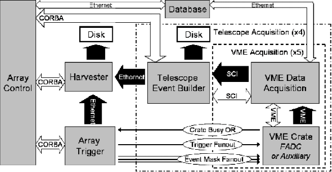
VERITAS [1] is an array of 4 imaging Cherenkov telescopes designed to record images of gamma rays impacting the atmosphere. Photo-multiplier signals accompanying an image trigger [4] are processed using a 3-tiered data acquisition system that operates at the VME crate, telescope, and array levels. The VME data acquisition guides the control and read out of the electronics channels. At the telescope level, the Event Builder combines data from each VME crate into events. At the array level, the Harvester collects events from each telescope and the array trigger and forms the final data product. Figure 1 shows a schematic of the data flow and communication between the processes.
1.1 The VME Data Acquisition
The VME Data Acquisition (VDAQ) serves as the interface to five VME crates that participate in the digitization of the PMT signals and the channel-level triggering for each telescope. Four of these contain 500 MS/s flash ADC modules with a clock-trigger module [2] and a fifth serves as an auxiliary crate housing a specialized clock-trigger module and a GPS clock (TTM637VME). The FADC electronics and the constant fraction discriminators (CFDs)[3] that produce individual channel triggers are housed on 10-channel 9U VME modules. The required complement of FADC channels to accomodate the 499-pixel camera are distributed among 4 crates of 12 or 13 FADC modules.
Each crate is controlled by a VMIVME 7807 Intel Pentium M 1.8 GHz single board computer running Linux. An additional Dolphin PCI mezzanine card provides a communication link using the ANSI/IEEE 1596-1992 Scaleable Coherent Interface (SCI) standard. Each of the VME crates and the telescope Event Builder are connected as nodes of a low-latency, high-throughput network. The configuration used in VERITAS achieves transfer rates of 50 MBytes/s. Data transfers and general communication between VDAQ and the telescope Event Builder are conducted via this interface. Each crate can be accessed via GBit ethernet for starting and halting the acquisition process.
A 24-sample (48 ns) FADC trace translates into an event fragment size of 3880 bytes for a crate of 13 modules (130 channels). Event fragments are collected and buffered until the accumulated size reaches 8 MBytes (2200 events for FADC crates). The buffer is then shipped to the telescope Event Builder. The transfers from the VME crates happen asynchronously for crates containing different numbers of modules. The typical data rate for a crate is 780 kBytes/s, which is well below the maximum rates permitted by the SCI and the Event Builder. The chief limitation on the system throughput arises from the data transfer rate over the VME backplane.
VDAQ is an event-driven process while the telescope and array acquisition processes are buffered. The telescope deadtime is incurred only at the VME level and is dominated by the size of the crate event fragments. For an array trigger rate of 200 Hz, the deadtime at an individual telescope is about 8.5%.
Hardware Configuration. Upon initiation, the VDAQ process for each crate generates a physical map of the modules present by type and, if applicable, a unique board identifier. Each crate provides this map to the Event Builder and uses it internally to procure hardware configuration parameters for each FADC channel and CFD. A variety of programmable features of the FADCs and CFDs are configured [2, 3]. While some parameters are unique to an individual physical component and must be associated by a uniqe identifier, others are properties of the telescope and pixel to which a channel is connected. The configuration settings and component mappings are stored in a MySQL database. This solution suits the distributed nature of the crate acquisition and accomodates the mappings required to properly configure the hardware. An additional benefit is an accurate log of the mappings and settings used.
Trigger Synchronization. After initialization and configuration, the acquisition processes await signals from the array trigger or commands from the Event Builder. The clock-trigger module in each crate generates a busy level during FADC reads when triggers cannot be accepted. To keep the five-crate system aligned, the busy levels are combined into a single telescope busy level and applied locally as a veto to incoming triggers. This signal is sent to the array trigger [4] to indicate when the telescope cannot accept triggers.
Trigger Type Handling. Upon receipt of an array trigger, each crate is passed a serialized event mask that contains an event number and a trigger type code. The mask is encoded into the event fragment via the clock-trigger boards to allow sychronization by the Event Builder. The trigger code is read by VDAQ and can be used to indicate special requests for FADC functions from the array trigger. Out-of-time reads of the FADC memory buffer are used to assess pedestal values periodically during observations. Upon receipt of a pedestal trigger code from the array trigger, VDAQ invokes a dedicated hardware command in the FADCs. Pedestal events are included in the data as normal events distinguished by their type code.
Trigger Rate Measurements. VDAQ accesses CFD trigger rates via the FADC modules. Scaler counts for each channel are read every 400 events, about once every 2 seconds; this is not often enough to impact the deadtime significantly. The CFD scalers are packed as a specially tagged event and shipped to the Event Builder as part of the regular SCI transfer. Scaler reads are included during normal observations to provide direct diagnostics of channel-level triggering.
1.2 The Telescope Event Builder
Each VERITAS telescope has a dedicated Telescope Event Builder which is responsible for combining the event fragments from each of the five VME crates to produce telescope events; these are then written to local disk and sent via GBit ethernet to the Harvester system. The Telescope Event-Building system is a Dual Intel Xeon Server machine running linux and using a local RAID array. Communications with and control of the Event Builder program is achieved through use of CORBA (Common Object Request Broker Architecture, specifically OmniORB). The Event Building Software is written in C++ and is fully multithreaded, typically containing five threads whilst running: Communications, SCI Buffer Acquisition and Parsing, Event Building, Disk Writer, Network Writer.
At the start of each night, the Event Builder queries each VDAQ crate for a map of present VME modules and then dynamically configures itself. Data is buffered at each of the VDAQ machines and transferred in blocks to the Event Builder via the SCI system. The Event Builder parses these memory blocks and extracts pieces of individual events, tagged by unique event numbers, which are then stored in memory. When all of the pieces of an event have arrived, the telescope event is built and buffered. Once roughly 160 kBytes of telescope events have been accumulated, the events are then dispatched to the “Consumers”. The Consumers are processes that receive built data buffers. They utilize a common architecture and, at run-time, any number of consumers may be registered. Typically only two are; the Disk Writer and Network Writer, but an additional Data Integrity Monitor consumer may also be used. It is estimated that the throughput of the Telescope Event-Building system on a dual 2.4 GHz Xeon server is approximately 12 MBytes/s. In addition to receiving actual event data, the Telescope Event Builders periodically receive CFD scaler data as described in the previous section. These data are not transferred with the event data, but simply stored and made available via CORBA to any system that requests the information.
1.3 The Harvester
VERITAS back-end data acquisition is the task of the Harvester – a single eight-core machine that collects data from all telescopes in real-time in addition to a stream of meta-data from the L3 trigger. The Harvester accomplishes four tasks:
Storing data. The Harvester saves all data streams to its fast RAID in real time. The current strategy for real-time data storage is to create a separate file for each telescope; this makes it possible to handle the separate telescope streams in parallel with minimal interaction.
Combining data. In addition to saving the data, the Harvester combines it in real time into array events. In this way, real time diagnostics can see a “big picture” of what the array is doing, rather than having to deal with telescopes individually.
Diagnostics. The Harvester runs a variety of real-time diagnostics – ranging from sanity checks to see if telescopes read out when they were supposed to, to a complete high-performance stereo analysis package that serves as the VERITAS real-time quicklook. During a run, the observer has up-to-the-second knowledge of the performance of the system.
Creating the final product. After a run completes, the Harvester immediately starts combining the data streams from the run to create a single file using the VERITAS Bank File (VBF) data format.
VBF groups telescope events together, such that given an event number, the user has immediate access to the corresponding events from all telescopes, in addition to meta-data from the array trigger. Thus, the analysis does not need to correlate stereo events; this task is already accomplished by the data acquisition system.
VBF has been designed for portability, high performance reading and writing, compactness, and extensibility. High performance access and compactness are achieved using a custom scheme for compressing FADC samples based on picking a different number of bits-per-sample depending on the dynamic range of each particular trace. This scheme overwhelmingly outperforms gzip and bzip2 in reading and writing times while reaching similar compactness. See Table 1 for performance measurements
| VBF Variant | Space Usage | Read Time |
|---|---|---|
| Uncompressed | 100% | 100% |
| w/ Gzip | 42% | 114% |
| w/ Bzip2 | 35% | 514% |
| Compressed∗ | 38% | 64% |
| Comp. w/ Gzip | 32% | 93% |
| Comp. w/ Bzip2 | 30% | 471% |
The observer interacts with the Harvester using the VERITAS array control software, as well as a suite of GUIs designed to view the results of quicklook analysis. The stereo analysis performed by the VERITAS quicklook system is capable of a very high level of performance – both in time and in sensitivity. A typical twenty minute run takes two minutes to analyze using quicklook. Further, the quicklook analysis results are comparable to offline analysis packages. Thus, we have confidence that if a bright source appeared in our field of view during observations, quicklook would have as good of a chance of seeing it as a manually performed offline analysis.
2 Conclusion
The VERITAS data acquisition systems combine a variety of hardware and software resources to achieve efficient and reliable operation from the reading of FADC data to the building and storage of event data. Diagnostic information is available at all levels and real-time analsyis is performed to ensure data quality. The system has proven highly adaptable and meets the needs of a variety of configuration and calibration tasks. All systems operate within design parameters and leave room for the exploration of low-threshold regimes.
Acknowledgments
This research is supported by grants from the U.S. Department of Energy, the U.S. National Science Foundation, and the Smithsonian Institution, by NSERC in Canada, by PPARC in the UK and by Science Foundation Ireland.
References
- [1] G. Maier. Status and Performance of VERITAS. In These Proceedings, 2007.
- [2] P. F. Rebillot, J. H. Buckley, P. Dowkontt, and K. Kosack. The VERITAS Flash ADC Electronics System. In International Cosmic Ray Conference, volume 5, page 2827, July 2003.
- [3] V. V. Vassiliev, J. Hall, D. B. Kieda, J. Moses, T. Nagai, and J. Smith. Veritas CFDs. In International Cosmic Ray Conference, volume 5, page 2851, July 2003.
- [4] A. Weinstein. The VERITAS Trigger System. In These Proceedings, 2007.