The influence of the structure imperfectness of a crystalline undulator on the emission spectrum
Abstract
We study the influence of an imperfect structure of a crystalline undulator on the spectrum of the undulator radiation. The main attention is paid to the undulators in which the periodic bending in the bulk appears as a result of a regular (periodic) surface deformations. We demonstrate that this method of preparation of a crystalline undulator inevitably leads to a variation of the bending amplitude over the crystal thickness and to the presence of the subharmonics with smaller bending period. Both of these features noticeably influence the monochromatic pattern of the undulator radiation.
pacs:
41.60.-m, 61.82Rx, 61.85.+p, 61.50.-f1 Introduction
In this paper we present the qualitative and quantitative analysis of the influence of imperfect structure of a crystalline undulator (in particular, the influence of the variation of the bending amplitude over the crystal thickness due to the stress applied to its surface) on the spectral distribution of the radiation. The parameters of crystalline undulators (including the types and lengths of crystals, the periods of bending, the positron energies, and the range of photon energies) as well as the methods of preparation of periodically bent structures discussed below in the paper correspond to those which are available for the experiments to be carried out within the PECU project[1].
A periodically bent crystal together with a bunch of ultra-relativistic charged particles which undergo planar channeling constitute a crystalline undulator. In such a system there appears, in addition to the well-known channeling radiation, the undulator type radiation which is due to the periodic motion of channeling particles which follow the bending of the crystallographic planes[2, 3]. The intensity and characteristic frequencies of this radiation can be varied by changing the beam energy and the parameters of bending. In the cited papers as well as in the subsequent publications (see the review Ref. [4] and the references therein) a feasibility was proven to create a short-wave crystalline undulator that will emit intensive monochromatic radiation when a pulse of ultra-relativistic positrons is passed through its channels. More recently, it was demonstrated [5] that the undulator based on the electron channeling is also feasible. A number of corresponding novel numerical results were presented to illustrate the developed theory, including, in particular, the calculation of the spectral and angular characteristics of the new type of radiation.
Although the operational principle of a crystalline undulator does not depend on the type of a projectile below in this paper we will consider the case of a positron channeling. Under certain conditions [2, 3], an ultra-relativistic positron, which enters the crystal at the angle smaller than the Lindhard critical angle [6], will penetrate through the crystal following the bendings of its planes. Provided the bending amplitude greatly exceeds the interplanar distance (see figure 1 left) one can disregard the oscillations due to the action of the interplanar force, – the channeling oscillations[6]. In this case the trajectory of the particle can be associated with the periodic profile of channel centerline. The undulator radiation appears as a result of this periodic motion of the particle. Thus, the operational principle of a crystalline undulator is the same as for a conventional one[7, 8], in which the monochromaticity of the radiation is the result of a constructive interference of the photons emitted from similar parts of trajectory.
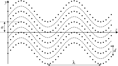
Usually, when discussing the properties of a crystalline undulator and of its radiation, one considers the case of a perfect crystalline undulator. By this term we will understand the crystal whose planes are bent periodically following a perfect harmonic shape, , see figure 1 (left). For clarity, let us stress that we consider the case when the quantities , and satisfy the double inequality . Typically, Å, and . The spectral-angular distribution from the perfect undulator is characterized by a specific pattern which implies that for each value of the emission angle the spectrum consists of a set of narrow, well-separated and powerful peaks corresponding to different harmonics of radiation. In principle, the perfect crystalline undulators can be produced by using the technologies of growing Si1-xGex structures [9]. In this case, by varying the Ge content one can obtain periodically bent crystalline structure [10, 11]. The technological restrictions imposed by this method on the crystalline undulator length is m.
The periodic bending can also be achieved by making regularly spaced grooves on the crystal surface either by using a diamond blade [12, 13] or by means of laser-ablation. The latter method was used [14] to prepare the Si-based crystalline undulators for the PECU experiments. In either case, the regular surface deformation results in the periodic pattern of the crystallographic planes bending in the bulk. The question which appears in connection with these methods of preparation concerns the quality of the periodically bending. Indeed, for a crystal of a finite thickness it is natural to expect that the surface deformations, regularly spaced with the period , result in the volume deformations of the same period but of a varied amplitude of bending, (see figure 1 (right)). The latter has maximum value in the surface layer but decreases with the penetration distance. Therefore, it is important to carry out a quantitative analysis (a) of the structure of this imperfect periodic bending in the bulk, and (b) of its influence on the spectrum of undulator radiation. Both of these problems constitute the subject of the present paper.
The paper is organized as follows. In section 2 we briefly outline the basic formulae and definitions which refer to a perfect crystalline undulator. Section 3 describes, in general terms, the modifications to be introduced to the formalism due to the imperfectness of the crystalline undulator. In section 4 we present the formalism and carry out numerical analysis of the periodic deformations in the bulk caused by a regular stress applied to the crystal surface. Finally, in section 5 we carry out quantitative analysis of the differences in the emission spectra formed in a perfect undulator and in the undulator created by means of periodic surface deformations.
2 Spectral-angular distribution of the radiation from a perfect crystalline undulator
The spectral distribution of the energy of radiation emitted by an ultra-relativistic () positron in a perfect crystalline undulator can be written in the following form [15, 16]:
| (1) |
where and are the emission angles with respect to the undulator axis chosen along , is the emission solid angle. The factor is explained further in this section. The function is given by
| (2) | |||
| (3) |
Here is the fine structure constant, is the relativistic Lorentz factor with standing for the positron mass and for its energy, and is the undulator parameter,
| (4) |
The parameter is defined as follows
| (5) |
A peculiar feature of the undulator radiation is that for each value of the emission angle the spectral distribution consists of a set of narrow and equally spaced peaks (harmonics) the frequencies one defines letting :
| (6) |
The widths of the peaks satisfy the inequality , so that all peaks are well separated.
In an ideal undulator (i.e., in which positrons and photons propagate in vacuum)111The term ’ideal undulator’ must not be mixed up with the term ’perfect undulator’, which is used throughout the paper and stands for the crystalline undulator with a perfect harmonic pattern of periodically bent channels. the peak intensity is proportional to the squared number of periods. Formally, it follows from the fact that is proportional to which behaves as for integer (e.g., [7]). This factor reflects the constructive interference of radiation emitted from each of the undulator periods. Consequently, in an ideal undulator one can increase unrestrictedly the radiated intensity by increasing of the undulator length .
The situation is different for a crystalline undulator, where the number of channeling particles and the number of photons which can emerge from the crystal decrease with the growth of . In Refs. [15, 16] the quantitative study of the influence of the dechanneling and the photon attenuation on the spectral-angular distribution was presented. The main result of this analysis is that the peak intensity is no longer proportional to . It was shown, that in a crystalline undulator the factor must be substituted with , which depends not only on and but also on the ratios and . Here stands for the dechanneling length which is the mean penetration distance covered by a channeling particle. The quantity , called the attenuation length, defines the scale within which the intensity of a photon flux propagating through a crystal decreases by a factor of due to the processes of absorption and scattering. A convenient formula for , which enters the right-hand side of (1), is as follows [16]:
| (7) | |||||
where (with being the closest positive integer to ).
Despite a cumbersome form of the right-hand side of (7) its main features can be easily understood. The most important is that, as in the case of an ideal undulator (to which reduces in the limit ) the main maxima of correspond to integers, and, therefore, the harmonic frequencies are still defined by (5) with . For finite and , the maximum value of is smaller than whereas the width of the peak is larger than that in the corresponding ideal undulator.
The attenuation length depends on the photon energy, , and can be calculated as the inverse mass attenuation coefficient which are tabulated for all elements and for a wide range of photon frequencies [17, 18].
The dechanneling effect stands for a gradual increase in the transverse energy of a channeled particle due to inelastic collisions with the crystal constituents [6]. At some point the particle gains a transverse energy higher than the planar potential barrier and leaves the channel. In a straight crystal dechanneling length of a positron depends on the crystal and on the energy of the projectile. In a bent crystal the potential barrier changes due to the centrifugal force, and, as a result, becomes dependent on the curvature of the channel. A stable channeling of a projectile in a periodically bent channel occurs if the maximal centrifugal force in the channel is less than the maximal interplanar force , i.e. . For an ultra-relativistic particle , where is the minimum curvature radius of the bent channel. In a perfect crystalline undulator , therefore, the condition for a stable channeling reads [2]:
| (8) |
Using the diffusion model [19] one can be demonstrated that dechanneling length in a periodically bent crystal becomes dependent on the parameter . In the case of ultra-relativistic positrons the expression for can be written as follows [3, 20]:
| (9) |
where is the dechanneling length a straight channel. This quantity can be estimated as [3, 19], where and are the classical radius of the electron and the Thomas-Fermi radius of the crystal atom, and ( stands for an average ionization potential of the atom).
Apart from the dechanneling length, the bending parameter also defines another important quantity, the acceptance of the crystal. The acceptance represents by itself the fraction of the particles trapped in the channeling mode (or, in other words, it is equal to the ratio of the phase volume corresponding to the channeling regime to the phase volume of the beam particles at the entrance of the crystal). In comparison with a linear crystal, the acceptance of the bent crystal gains additional decrease due to the presence of the centrifugal force in the channels [19]. Generalizing the result of Ref. [21], one writes the following expression for the acceptance of the periodically bent channel and for the case of a parallel beam:
| (10) |
where is the acceptance of the linear crystal and . If the centrifugal force exceeds the interplanar force (i.e., ) then one uses the identity , which means that the channel does capture the particles.
In connection with the radiation from a crystalline undulator, the acceptance comes into play when one calculates the energy emitted per particle of the bunch. To obtain this quantity in a perfect undulator, one multiplies the right-hand side of (1) by the acceptance .
The formulae (1)-(10) allow one to carry out numerical analysis of the spectral-angular distribution formed in a perfect crystalline undulator. In a recent paper [22] the results of such analysis were reported for 0.6 and 10 GeV positrons channeling through periodically bent Si and Si1-xGex crystals.
3 Emission from the undulator with a varied bending amplitude
In this section we analyze the modifications in the formalism of spectral-angular distribution of the radiation from a crystalline undulator which appear due to the imperfectness of periodic bending of the crystallographic planes.
For the sake of clarity let us discuss the geometrical conventions which will be used below. Figures 1 and 2 help a reader to follow the text. We assume that the crystal has the form of a rectangular box. Its length, , width, , and thickness, , are measured along the , and directions, respectively. We chose the frame in which the values denote the -coordinates of the upper and lower surfaces of the crystal. Hence, it is assumed that labels the central -plane of the crystal (the midplane). Initially non-deformed crystallographic planes are perpendicular to the axis. We assume that periodic deformation of the crystalline structure occurs only in the -plane, so that there is no deformation in the -direction. In the deformed crystal the bunch of channeling particles propagates in the -plane along direction. With we denote the bunch size along the direction. The width of the bunch (i.e., its size in ) is not used in our model.
Suppose that bending amplitude is not constant over the crystal thickness but changes according to a law , as illustrated by figure 1. The particular form of this dependence is discussed in Section 4 where we analyze the deformation of the crystal interior due to the periodic stress applied to its surfaces. At the moment, the only restrictions implied on the dependence are: (a) the change in amplitude on the scale of interplanar spacing is negligible; (b) a strong inequality is valid for all .
Particles in the bunch are randomly distributed along the -axis. Therefore, we may assume that at the entrance a particle can be captured in any channel located within the interval , where stands for the smallest from and . Being captured in the channel at some point, the particle undulates and emits the radiation corresponding to the undulator with the amplitude . For a fixed value of the period , the amplitude defines two important quantities which are the undulator parameter and the bending parameter . The latter, in turn, defines the dechanneling length and the acceptance (see eqs. (9) and (10)). The influence of and on the spectral-angular distribution of radiation is discussed in detail further in this section. Here we note that the acceptance determines the probability of a particle to be captured in the channeling more. If , this probability depends on the entrance coordinate . Therefore, to obtain the distribution (per particle) of radiation formed in the crystal with varied amplitude of bending one should (a) multiply eq. (1) by the acceptance (10), and (b) carry out the averaging over the interval . This leads to the formula:
| (11) |
Here stands for the the distribution (1) obtained for the amplitude . The right-hand side of this equation represents the spectral-angular distribution per particle averaged over the width of the crystal (or of the bunch if )222The contribution to the integral comes only from the regions where , otherwise , see eq. (10). . If the amplitude does not change within the interval of integration, the formula (11) reduces to eq. (1) multiplied by the acceptance corresponding to the fixed -value.
Let us discuss in more detail the influence of the dependence on the characteristics of the crystalline undulator radiation.
It is clear that for the -varying amplitude the terms, dependent on in the function (see (2)), change with since (see (4)). Apart from this influence, the proportionality can lead to the variation of the harmonics frequencies and, consequently, to the loss of the monochromaticity of the radiation. Indeed, let and denote the minimum and maximum amplitudes within the interval . The corresponding extremum values of the undulator parameter, and , having been used in (6), produce the lower, , and the upper, , bounds on . In the limit there is a weak variation of the harmonics frequencies, . However, in the case the change in the undulator parameter leads to the emission within the band which can greatly exceed not only the peak width but also the interval between the neighbouring harmonics. In the latter case the monochromaticity of the radiation will be smeared out if one carries out the averaging procedure (11).
However, the change in the undulator parameter and the harmonics frequencies is not the only impact caused by the amplitude variation. As mentioned above, in a crystalline undulator the peak intensity is defined by the maximum value of the factor , which depends on the ratios and (see (7)). Typically, in the crystalline undulators based on GeV positrons channeling in crystals (so far Si monocrystals and Si-Ge mixtures were used [14, 23]) the energy of emitted photons lies within the range keV. For these energies of positrons and photons the attenuation length is on the level of several cm [17] and by far exceeds the positron dechanneling lengths (lying within cm in straight channels [22]). Therefore, assuming in (7), one finds that the peak value of the factor (i.e., at ) in an undulator with fixed number of periods, , is given by
| (12) |
The dechanneling length in a channel, which is periodically bent with the amplitude , is defined by equations (8) and (9). Hence, for the right-hand side of (12) (and, generally, of (7) as well) becomes dependent on since with . In turn, the variation of the factor can strongly influence the averaged spectral-angular distribution (11).
4 Periodic deformations in bulk
In this section we present a formalism which allows one to carry out a quantitative analysis of the parameters of periodic bending in the bulk of a crystal. We consider the case when the bendings in the bulk are due to the periodic deformations on the crystal surfaces. Such a situation is illustrated by Figure 2: two parallel opposite surfaces are deformed periodically by means of identical sets of parallel grooves applied to each of the surfaces (the two sets are shifted by half-period, ).
The deformation of this type can be achieved either by mechanical scratching of the crystal surface [12, 13] or by means of a more accurate laser-ablation method [14]. Another possible method is in a deposition of Si3N4 layers onto a Si wafer [13].
In either case the crystallographic planes in the bulk become bent periodically although the shape of bent planes does not follow an ideal harmonic form . The main deviations are: (a) the amplitude of bending depends on the distance from the surface, and (b) in general case, higher subharmonics (i.e. the Fourier components of with smaller periods, , where ) contribute noticeably into the formation of the periodic shape.
However, as we demonstrate below, it is possible to establish the ranges of parameters (these include , the thickness and elastic constants of the crystal) within which the deviations of the resulting periodic shape from the ideal form do not affect the spectral-angular distribution of the undulator radiation.

4.1 The equations of equilibrium with periodic boundary conditions
To start with, let us formulate the approximations which will be used in our formalism.
Firstly, we assume that the width of a crystal (i.e. its size in the -direction, see figure 2) is much larger than the thickness : . As a result, one can disregard the deformations in the -direction and consider the deformations of a solid body in the -plane only. Additionally, we assume that the period is incomparably smaller than the length of the crystal in the direction. Then, taking into account the periodicity of the surface deformations, one represents the displacement vector (i.e. the vector which characterizes the change in the position vector of a point in the body due to the deformation) in the form of Fourier series:
| (13) |
where . The vectors (with standing for an integer) are to be defined by solving the equation of equilibrium with proper boundary conditions. In what follows we adopt that the coordinate is measured from the crystal midline, and thus corresponds to the lower surface, and - to the upper one.
Secondly, we will consider the limit of small deformations only. In this case the strain tensor is defined as follows (see, e.g., [24]):
| (14) |
with and .
The third approximation concerns the stress tensor, (we remind, that physically stands for a stress on the -th plane along the -th direction). In an isotropic media the components of the stress tensor can be related to by means of the two elastic constants: the Young’s modulus and the Poisson’s ratio . In the case of a planar deformation the relationship is as follows (see, e.g., §5 in [24]):
| (15) |
In anisotropic media (e.g., in a crystal) and depend on the directions of the applied stress and of the deformation. For example, depending on a crystallographic direction the Poisson’s ratio and the Young’s modulus in a Si crystal varies within the intervals and GPa [25]. However, to simplify the analysis one can chose some average values. In our numerical analysis we use and GPa which are close to the values used in modeling various deformation processes in silicon [13, 26]. To check the sensitivity of the results to the choice of the Poisson’s ratio we also carried out the calculations using the extreme values of in silicon. It turned out that nearly an order of magnitude change in does not noticeably affect the results which are presented below in the paper.
The components of the stress tensor satisfy the following equations of equilibrium:
| (16) |
Using (13)–(15) in (16) one derives the system of coupled equations for the functions and :
| (17) |
To find the unique solution of this system one has to impose the boundary conditions. These can be formulated as follows.
Each trench acts as a source of a normal (‘’) and a tangential, or a shear () tension which are characterized by the average pressures and applied to the crystal surface in vicinity of the trench. In the case when the period the width (see figure 2), the trenches are equivalent to the sets of concentrated normal and shear forces applied along the equally spaced lines on the upper and lower surfaces 333The condition is well fulfilled in the crystalline undulators which have been manufactured. Typical values are: m and m [12, 13, 14, 23]. . Within this model the pressures and can be related to the components of the stress tensor calculated at the upper () and the lower () surfaces.
Let us first formulate the boundary conditions due to the normal tension. The pressure is applied inward the crystal along straight lines, parallel to the axis, passing through the equally-spaced points in the direction. Therefore, recalling that represents the -th component of the force per unit area (with standing for the -th component of the outward-pointing normal) one derives the boundary conditions:
| (18) |
Here the coefficient ensures that the period-averaged pressure, equals to . The arguments of the delta functions fix the coordinates of the lines parallel to the axis. As mentioned, the sets of trenches on the upper and lower surfaces are shifted by , and this explains the difference of the arguments of the delta functions for and .
In the case of shear stress, supposing that the trench profile is symmetric, one notices that the tangential forces created at the opposite edges of a trench are equal in magnitude but are antiparallel. Therefore, the component as a function of must change the sign when crossing a trench. It means that in the limit of infinitesimal width this component becomes proportional not to the delta functions as in (18) but to their derivatives. As a result, one writes the boundary conditions in the form:
| (19) |
where stands for the tangential force associated with the period-averaged pressure .
With the help of (13)–(15) the equations (18) and (19) can be re-written in terms of the functions and taken at . The obtained formulae suffice to determine completely the solutions () for the normal or the shear stress. To obtain the solution in the case when both types of stress act simultaneously one constructs the corresponding linear combinations of the functions and .
Using these functions further in (13) one determines the displacement vector . The component of this vector is of a special interest in connection of the crystalline undulator problem since it determines the profile of the periodically bent channel in the bulk.
4.2 Displacement in the cases of normal and shear stresses
Let us first analyze the periodic deformation in the bulk due to the normal and the shear stresses separately.
Resolving the system (17) with the boundary conditions (18) (or (19)) one finds the functions (or ) for all . Using these in (13) one represents the -component of the displacement vector in the following form:
| (20) |
Here can be associated with the amplitude of the th harmonic of teh periodic bending, i.e., the one with the period . A perfect crystalline undulator (see figure 1, left panel) is characterized only by the term whose amplitude is independent on . However, if a crystalline undulator is prepared by applying concentrated periodic normal or shear stress then: (a) higher amplitude harmonics (with ) appear, and (b) the homogeneity of the bending amplitudes is lost since they become -dependent. To stress these features of the amplitudes one can use the formulae which conveniently expresses via - the first harmonic amplitudes is the midplane of the crystal (i.e. in the -plane with ).
In the case of normal stress alone the formula is as follows:
| (21) |
For a shear stress the relationship reads:
| (22) |
In (21) and (22) the following notations are used:
| (23) |
and
| (24) |
The amplitudes are proportional to the applied stresses and are given by:
| (25) |
where
| (26) |
Let us note that due to the half-period relative displacement of the deformations on the upper and lower surfaces of the crystal the amplitudes with odd values of are even functions of and vice versa (see (21) and (22)). Therefore, it is sufficient to analyze the amplitudes in the upper half of the crystal, i.e. for .
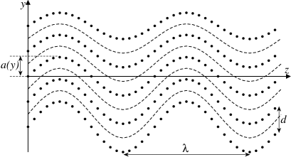
4.3 Numerical results for the bending amplitudes and
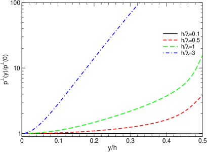
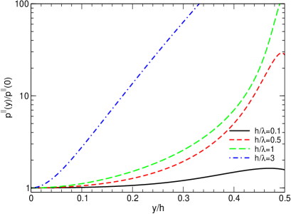
The behaviour of the ratios and as functions of the scaled distance from the midplane is illustrated by figures 3 and 4. The dependences were calculated for several values of the crystal thickness (measured in the periods as specified by the ratio ) and several even and odd values of . The data refer to a Si crystal and the Poisson’s ratio was chosen as .
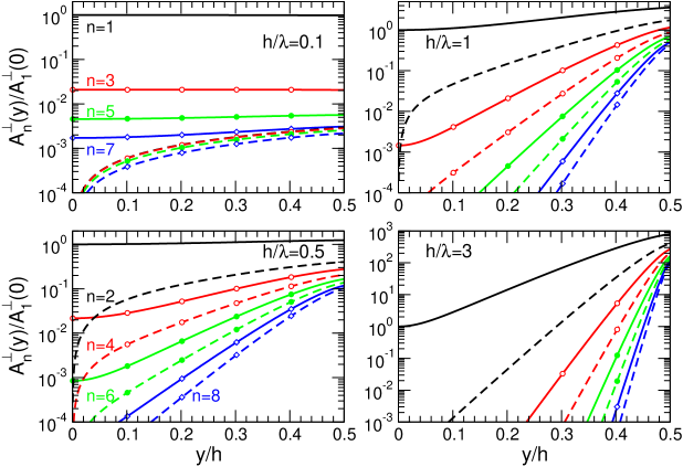
It is clearly seen from the figures that for either type of stress the inhomogeneity of the bending amplitudes along the direction is much more pronounced for a thick crystal (i.e., when ) than for a thin one with .
Indeed, in the limit the amplitudes corresponding to odd values of do not vary noticeably over the crystal thickness. Being even functions of , the odd- amplitudes depend quadratically on in the vicinity of the midplane, , and have minimum at . In a thin crystal the quadratic term is small for all provided satisfies the condition written above. As a result, for these . The main reason for the even- amplitudes to vary even in the case of a thin crystal is that they are odd functions of . Therefore, being non-zero at the surfaces these amplitudes attain zero in the midplane. (A non-monotonous behaviour of for particular and , which is most pronounced for the curves on the top left graph of figure 4, just reflects the fact that the right-hand side of (22) is not, generally, a monotonous function of .)
Another important feature of a thin crystal is that over the whole thickness the amplitude with greatly exceeds those with higher . This dominance is more pronounced for a normal stress than for a shear one as reflected by additional factor on the right-hand side of (21). As a result, the terms with prevail in the series from (13), so that the periodic bending in a thin crystal is of nearly harmonic shape: .
As the crystal thickness increases the variation of the amplitudes over half-width evolves dramatically. In the case of a thick crystal this variation reaches orders of magnitudes. Such a behaviour one understands analyzing the right-hand sides of (21) and (22). Assuming one derives the following expressions for the amplitudes on the surface and in the midplane:
| (29) |
where in the case of a normal stress and for a shear stress. For even the identity is valid.
Equations from (29) demonstrate that for all the amplitudes decrease exponentially with the penetration distance into the crystal. For a fixed odd the decrease rate can be characterized by the ratio , which is, basically, independent on the type of applied stress (the difference manifests itself only in the pre-factor ). On the other hand, the first line in (29) indicates that in the limit of a very thick crystal the amplitudes weakly depend on in a surface layer of the width (this dependence is more pronounced in the case of a normal stress due to the additional factor ). These two features of the amplitude suggest that deviation of the periodic bending from the harmonic shape is very strong in the outer layers of the crystal whereas in the central layer the terms with are negligibly small and the profile of bending is nearly perfect. The deviation of the amplitudes from their values at is described by the following formulae:
| (30) |
To conclude this section we note that figures 3 and 4 suggest that the use of crystalline undulators manufactured by means of periodic surface deformation can be justified in two cases (irrelevantly to the type of the stress applied to crystal).
Firstly, it is the limit of a thin crystal which ensures (a) the (nearly) constant value of the amplitude , and, (b) a small contribution of higher- terms to sum on the right-hand side of (20).
Secondly, for it is meaningful to use only the central part of the crystal, i.e., where , as an undulator. In this case it is necessary to use a narrow beam (along the -direction) which is accurately aligned with the crystal midplane.
4.4 Estimation of the variation of the undulator parameter and the bending parameter
Equation (20) shows that in general case the profile of bending contains contributions of the terms with various thus deviating from a pure harmonic shape . Hence, it is meaningful to analyze the influence of this deviation on the undulator parameter and the bending parameter which, as it was discussed at the end of section 3, are of importance for the calculation of the averaged spectral-angular distribution (11) of radiation.
4.4.1 Variation of the undulator parameter .
Generally, the parameter characterizes the mean-square velocity, , of the periodic transverse motion of a particle moving in an undulator (e.g., [27]). For an ultra-relativistic projectile the relationship is as follows: . In a perfect undulator this formula leads to equation (4). In the imperfect undulator discussed here, a particle moves along the trajectory defined by the right-hand side of (20) with . Calculating the transverse velocity and averaging over the period , one derives the expression for the undulator parameter as a function of :
| (31) |
where stands for the partial undulator parameters corresponding to the -th subharmonics of the trajectory.
In figure 5 we present the dependences of the ratio on calculated for several values of the crystal thickness and for the two types of stress, as indicated in the caption. As it was discussed in section 3 the dependence of the undulator parameter on leads to a variation in the harmonic frequencies (6) over the crystal thickness. If this variation becomes large enough (e.g., when the shift in the harmonic position becomes comparable with the separation of the neighbouring harmonics) then the spectral-angular distribution will loose the peak-like pattern typical for the undulator radiation. From this viewpoint the graphs from figure 5 allow one to estimate the influence of the change in the undulator parameter across the crystal cross section on the shape of spectral-angular distribution.
For both types of stress the dependences exhibit the common trend: the undulator parameter slowly varies with in the limit of a thin crystal but becomes a rapidly (exponentially) increasing function for a thick crystal. This is a direct consequence of the definition (31) and the behaviour of the amplitudes (see figures 3 and 4). Another peculiarity, which one notices comparing the two panels in figure 5, is that for the same value of the ratio grows faster than . Such a feature, which is more pronounced for higher values, can be understood if one recalls the differences in the -dependences of the bending amplitudes in the case of normal and shear stresses, and the behaviour of as functions of . Indeed, for moderate and large ratios and for both types of the stress, the amplitudes with , being rapidly increasing functions, satisfy the relations and (see (29)). Hence, for the sum on the right-hand side of (31) is defined, basically, by the term with , whereas for larger also the terms with higher contribute noticeably to the sum. On the other hand, it follows from (21) and (22) that , resulting in a similar estimate for the ratio of the partial undulator parameters: . Therefore, in the case of the shear stress the undulator parameter varies with more rapidly than for the normal stress.
Typically, in crystalline undulators prepared by means of surface deformation and based on GeV positron channeling [14, 23]), the values of parameter lie within the range . The curves in figure 5 allow us to estimate the degree of consistency of using the undulators with various and values.
It was pointed out in section 3, that there will be no dramatic change in the spectral-angular distribution of the radiation due to the imperfectness of the undulator provided the variation of the undulator parameter does not lead to a noticeable change in the position of the peaks located at the frequencies (see (6)). To analyze this condition let us consider, for the sake of clarity, emission in the forward direction (). In this case the frequency of the -th harmonics, radiated from the the channel located at the distance from the midplane, is given by
| (32) |
It is clear that in the limit the position of the peak will be practically unchanged for those where . These two inequalities, depending on the absolute value of , allow for a wide-range variation of the ratio , up to the order of magnitude. It follows from figure 5 that for a thin crystal such a situation can be realizes over the full thickness . In a thick crystal () only the central part ensures the needed variation of the undulator parameter.
In the opposite limit of large undulator parameters, when , the stability of the peak position can be achieved only in that part of the crystal where . Taking into account rapid variation of the ratio in the case of a thick crystal, one deduces that this inequality can be ensured only by using very thin crystals with .
4.4.2 Variation of the bending parameter .
The channeling process in a bent crystal takes place if the centrifugal force, , due to the channel bending is less than the interplanar force [28]. In a perfect crystalline undulator this condition, applied to the points of maximum curvature, results in the inequality (8) which relates with the period and the amplitude of periodic bending [2]. In the case when the profile of periodic bending contains a number of subharmonics, e.g., as in (20), is it more constructive to relate the parameter to the mean-square curvature where the averaging is carried out over the period . Recalling that the curvature is proportional to the modulus of the second derivative of the bending profile, , and carrying out the averaging, one derives the following expression for average bending parameter as a function of :
| (33) |
where
| (34) |
is the mean-square partial bending parameter corresponding to the -th subharmonics of the trajectory (20).
The parameter , being used in (9), defines the dechanneling length as a function of . As mentioned in section 3, the variation of over the crystal thickness may influence destructively the averaged spectral-angular distribution (11).
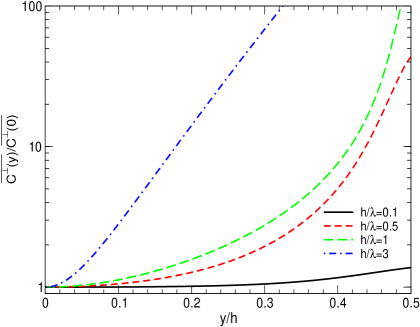
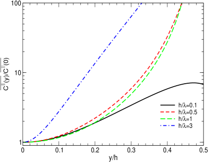
Figure 6 presents the dependences of , scaled by its value at the crystal center, versus calculated for several values of the crystal thickness and for the two types of stress, as indicated in the caption. Qualitatively, the behaviour of the curves is similar to those of the ratio discussed above. Nevertheless, there is a quantitative difference: for a fixed value of the curves increase faster with than the corresponding ratio of the undulator parameters. This feature is due to the difference in the -dependence of the partial terms in (20) and in (21). Indeed, the partial bending parameters behave as (see (22)) instead of the proportionality to of the partial undulator parameters. It was discussed in connection with figure 5 that for moderate and large values the terms with provide the increase of with . This increase is more pronounced for since its partial terms contain an extra factor .
A crystalline undulator can operate only in the regime when . If otherwise, then the centrifugal force will drive the particles out of the channel. More detailed analysis [15] indicated that the reasonable range for the bending parameter is . It means that if for the bending parameter is of the order of , then the variation of within the order of magnitude are acceptable. From figure 6 it follows that for a thin crystal such a situation can be realizes over the full thickness. In a thick crystal () only the central part ensures the needed variation of the bending parameter.
4.5 Calculation of corresponding to given amplitudes at the crystal center
The numerical data, discussed above in sections 4.3 and 4.4, represent the -dependence of the amplitudes, undulator parameters and bending parameters scaled by their values at . The latter, in turn, can be expressed in terms of the amplitudes which can be calculated from (25) and (26). These equations relate the amplitudes to the bending period .
In connection with a perfect crystalline undulator it was established (for a detailed discussion see [4]) that the operation of the undulator should be considered in the large-amplitude regime, i.e. when the bending amplitude is much larger than the interplanar distance . In this limit the characteristic frequencies of undulator and channeling radiation (see, e.g., Ref. [29]) are well separated. As a result, the channeling radiation does not affect the parameters of the undulator radiation, whereas the intensity of undulator radiation becomes comparable or higher than that of the channeling one [3].
To apply this approach to a crystalline undulator with varied amplitude one assumes that the large-amplitude regime is applicable to the amplitudes at the crystal midplane: . For the convenience of further consideration let us introduce the quantity
| (35) |
which explicitly measures the amplitude in the units of interplanar separation.
Other quantities, which enter equations
(25) and (26) include:
(a) The crystalline medium dependent parameters,
the Poisson’s ratio and the Young’s modulus .
(As already mentioned, for a Si crystal we use the average values
and GPa.)
(b) The crystal thickness , which enters via the ratio
.
(c) The applied stress, or .
To estimate the stress one takes into account that we are interested in elastic deformations of the crystalline structure. Therefore, must not exceed the plastic yield strength, , which stands for the stress at which material strain changes from elastic deformation to the plastic one. For a silicon crystal one can adopt GPa [30]. For further use let us introduce the quantity, which stands for the stress measured in the units of :
| (36) |
Using (35) and (36) one re-writes equation (25) as follows (to simplify the notations the superscripts ‘’ and/or ‘’ are omitted):
| (37) |
Explicit forms of the functions for the two types of stress are given in (26).
Relationship (37) allows one to find the values of and which ensure, for a given crystal (the parameters , and ) and for a relative stress (the parameter ), a desired value of the relative amplitude in the center of crystal.
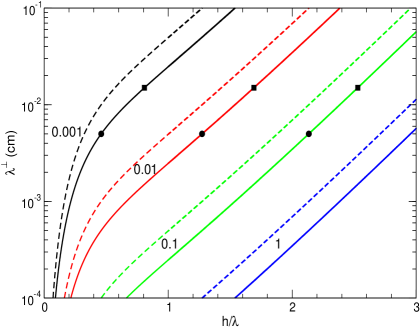
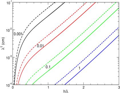
To illustrate the relationship we present figure 7, where the dependence of on is plotted for several values of (as indicated) and for two values of the relative amplitude, and . The two panels in the figure correspond to different types of the applied stress. It is seen that the and curves obtained for the same values of and look much alike although there is a distinguishable quantitative difference (note the log scale of the vertical axis).
5 Averaged spectra
In this section we present the results of numerical analysis of the influence of the periodic bending imperfectness on the spectral-angular distribution. The calculations were performed for two energies, GeV and eV, of a positron channeling along periodically bent (110) crystallographic planes in Si (the interplanar distance Å, the maximal interplanar force GeV/cm). The data presented below refer to the emission in the forward direction. (i.e., with respect to the axis, see figure 2). In this case the integrals (3) can be evaluated analytically and the spectral distribution (1) from an undulator with fixed parameters is expressed in terms of the Appel function [22, 31]. These features, being not too important physically, simplify the numerical analysis.
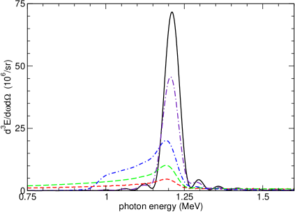
The parameters of the crystalline undulators used in the calculations were chosen as follows. Firstly, for both mentioned positron energies the amplitude of the subharmonic in the crystal center was fixed as , thus satisfying the large-amplitude condition (35). Secondly, for each the length of the crystal was chosen to be equal to the dechanneling length in the straight channel (see (9)): cm and cm for and GeV, correspondingly. The bending period is m for GeV (resulting in undulator periods), and m for GeV (with ). Using (32) with one calculates the energies of the first harmonics emitted in the perfect undulators (i.e., with the cited and values): keV and MeV for and GeV, correspondingly. Let us note that the mentioned values of positron energies, the crystal lengths and the parameters of periodically bent channels are close to those discussed recently in connection with the experiments on crystalline undulators [14, 22].
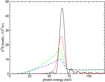
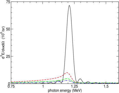
Two graphs in figure 8 correspond to two energies , as indicated in the caption. In each graph, the solid curve represents the profile of the first harmonic peak (in the forward direction) calculated using (1) for the perfect undulators with the parameters and given above. Other three curves in each graph correspond to the averaged spectra calculated for the same values of and but for different crystal thicknesses . These spectra were obtained from (11) by setting (the effective range of integration was restricted by the condition , see the footnote comment below eq. (11)). As it was mentioned in section 4.5, one can vary the crystal thickness together with the relative stress to achieve fixed values of (see (37)). The short-dashed, long-dashed and chained curves in the figure were obtained for the relative stress , and , respectively. The corresponding values of one finds from figure 7 (left), where the filled circles mark the ratios for GeV and the filled squares – for GeV.
Comparing different curves in the figure and recalling the discussion presented in section 3, one sees the extent to which the imperfectness of the undulator structure over the crystal thickness can influence the emission spectrum. The increase in (or, more generally, in the interval over which the averaging in (11) is carried out) leads to a more pronounced variation of the amplitudes (see figures 3 and 4). This, in turn, trigger strong variations of the effective undulator parameter and bending parameter , – figures 5 and 6. The increase in with results in the decrease of the first harmonic energy (see (32)). In the figure this feature is reflected by the (relative) enhancement of the photons with the energy smaller than the values of cited above. Thus, in the peaks in the averaged spectrum become wider and the width increases with . Another tendency, clearly seen in the figure, is the decrease in the peak intensity with . This is mainly due to the variation of the bending parameter . Indeed, varies from its minimum value at the center up to the in the surface layer, figure 6. For a given the value defines the dechanneling length , which, in turn, influences the peak value of the spectrum via the factor : smaller result in smaller peak intensities (see (7) and section 3). Additionally, the channel acceptance (10) decreases with increasing. Therefore, the relative contribution of the trajectories with larger -values to the integral from (11) increases with leading to the decrease in the peak intensity of the averaged spectrum.
The two features mentioned above are more pronounced for a positron energy GeV than for GeV (compare right and left graphs in figure 8). The reason is a s follows. For a 5 GeV positron, the undulator parameter at the center is which is noticeably larger than the value for a GeV positron. Hence, the influence on the position of the first harmonic peak due to the variation of the undulator parameter with is smaller for lower . As a result, the averaged peaks for GeV are (relatively) wider than those for GeV. The more pronounced decrease in the intensities for a GeV positron is due to the larger contribution of the trajectories with higher -values. This, in turns, happens because for the same value of the relative stress the relative thickness is higher for a GeV positron (compare the positions of filled squares and filled circles which correspond to the same values in figure (7)).
Figure 8 demonstrates that the pattern of spectral-angular distribution can change dramatically. The well-separated peak-like structure, typical for the emission spectrum from a perfect undulator, can be completely smeared out in the imperfect undulator due to the variation of the parameters of periodic bending. The degree to which the peaks are destroyed depends on the crystal thickness and on the values of the undulator parameter and the bending parameter at the center of the crystal. In particular, for and in the case of a thick crystal () the averaged spectrum has a nearly uniform distribution which is typical for the noise rather than for the undulator-type radiation.
However, even in the case of a comparatively thick crystals one can restore the coherence of radiation. To achieve this, it is necessary to avoid using the layers of the crystal located far off the centerline, i.e. to use not the whole thickness of the crystal but its central part of the width lower than . In the central layer, the amplitudes and the related quantities do not deviate noticeably from their values at (see (30)), and, therefore, the averaging procedure will not radically influence the peak profile.
To illustrate this statement, we present figure 9 which contains the spectral intensity in the vicinity of the first harmonic for the perfect undulator (the solid line) along with the averaged spectra calculated for different . The data refer to GeV positron channeling in a Si crystal with , the relative normal stress , the parameters and as in figure 8 right. The solid curves in figures 9 and 8 (right) are identical. The short-dashed curve (the lowest one) in figure 9 stands for the spectrum averaged over the whole thickness, i.e. . Other curves corresponds to smaller values, as indicated. It is clearly seen that by narrowing the averaging interval the profile of the line can be made closer to that for the perfect undulator.
6 Conclusions
In our paper we discussed the influence of imperfect structure of a crystalline undulator on the spectral distribution of the radiation. We mainly analyzed the undulators in which the periodic bending in the bulk appear as a result of regular surface deformations. We demonstrated that this method inevitably leads to two main deviations from the perfect harmonic shape . Thsese are: (a) the dependence of the bending amplitude on the distance from crystal midplane, and (b) the presence of subharmonics with smaller bending periods. As a result, the quantities which characterize the crystalline undulator, – the undulator parameter and the bending parameter , vary over the crystal thickness . In turn, this leads to the loss of the monochromaticity of the radiation formed in the undulator.
Typical scale, within which the parameters vary noticeably, is equal to the period of the surface deformations. As we demonstrated in the paper, one can choose the following two strategies to partly restore the monochromaticity of radiation. Firstly, one can use thin crystals, . In this case, the variation of the amplitude over the width as well as the contribution of higher subharmonics do not lead to dramatic changes in the spectrum. However, this limit corresponds to very thin crystals, if one takes into account that the period of surface deformations lies within the range m [12, 13, 14].
The second approach prescribes the use of a thick crystal but in combination with a narrow () positron beam along the midplane. This limit seems to be achievable by using existing positron beams in the GeV range and with the size (along one direction) of several microns (see [18]).
To minimize the destructive role of the imperfect structure, one can also consider alternative schemes of the surface deformations. Namely, if instead of just a periodic surface deformation one applies a harmonic surface deformation with a period , then the only imperfectness of the periodic bending in the bulk will be associated with the variation of the amplitude since for the amplitudes of subharmonics with will be identically equal to zero. This, in turn, will result in a much smaller variation of the undulator parameter and the bending parameter over the crystal width (see eqs. (31) and (33), and figures 5 and 6) since this variation is to a great extent due to the contribution of higher subharmonics. To achieve the harmonic shape of the surface deformation one can either place a crystal between two press molds of the harmonic profile (shifted by with respect to each other) or apply a modulated pressure by means of two piezoelectric layers.
References
References
- [1] http://ec.europa.eu/research/fp6/nest/pdf/nest_projects_september_2005_preview.pdf (pp. 31-32)
- [2] A.V. Korol, A.V. Solov’yov, W. Greiner, J. Phys. G 24 (1998) L45.
- [3] A.V. Korol, A.V. Solov’yov, W. Greiner, Int. J. Mod. Phys. E 8 (1999) 49.
- [4] A.V. Korol, A.V. Solov’yov, W. Greiner, Int. J. Mod. Phys. E 13 (2004) 867.
- [5] M. Tabrizi, A.V. Korol, A.V. Solov’yov, W. Greiner, Phys. Rev. Lett. 98 (2007) 164801; J. Phys. G 34 (2007) 1581.
- [6] J. Lindhard, Kong. Danske Vid. Selsk. Mat.-Fys. Medd. 34 (1965) 14.
- [7] D. F. Alferov, Yu. A. Bashmakov, P. A. Cherenkov, Sov. Phys. - Uspekhi 32 (1989) 200.
- [8] P. Rullhusen, X. Artru, P. Dhez, Novel Radiation Sources using Relativistic Electrons, World Scientific, New York, 1998.
- [9] M.B.H. Breese, Nucl. Inst. and Meth. B 132 (1997) 540.
- [10] U. Mikkelsen, E. Uggerhøj, Nucl. Inst. and Meth. B 160 (2000) 435.
- [11] A. V. Korol, W. Krause, A. V. Solov’yov, W. Greiner, Nucl. Inst. and Meth. A 483 (2002) 455.
- [12] S. Bellucci et al, Phys. Rev. Lett. 90 (2003) 034801.
- [13] V. Guidi, A. Antonioni, S. Baricordi, F. Logallo, C. Malagù, E. Milan, A. Ronzoni, M. Stefancich, G. Martinelli, A. Vomiero. Nucl. Inst. and Meth. B 234 (2005) 40.
- [14] P. Balling, K. Kirsebom, D.Q. Le, U.I. Uggerhøj, S. Ballestrero, S. Connell, J. Härtwig, F. Masiello. ‘Producing and investigating periodic deformations in silicon crystals’. Talk at the PECU meeting (Frankfurt am Main, 2007).
- [15] A.V. Korol, A.V. Solov’yov, W. Greiner, J. Phys. G 27 (2001) 95.
- [16] A.V. Korol, A.V. Solov’yov, W. Greiner, Proc. SPIE - Int. Soc. Opt. Eng. 5974 (2005) 597405.
- [17] J. H. Hubbel, S. M. Seltzer, Tables of X-ray Mass Attenuation Coefficients, NISTIR 5632 - Web Version 1.02, http://physics.nist.gov/PhysRefData/XrayMassCoef/cover.html.
- [18] W.-M. Yao, et al., J. Phys. G 33 (2006) 1.
- [19] V.M. Biruykov, Yu.A. Chesnokov, V.I. Kotov, Crystal Channeling and its Application at High Energy Accelerator, Springer, Berlin, 1996.
- [20] A.V. Korol, A.V. Solov’yov, W. Greiner, J. Phys. G 27 (2001) 95.
- [21] V.V. Kaplin, S.A. Vorobiev, Phys. Lett. 67 A (1978) 135.
- [22] A.V. Korol, A.V. Solov’yov, W. Greiner, Proc. SPIE - Int. Soc. Opt. Eng. 6634 (2007) 66340P.
- [23] V.T. Baranov et al, Nucl. Inst. and Meth. B 252 (2006) 32.
- [24] L.D. Landau, E.M. Lifshitz, Course of Theoretical Physics, vol.7. Theory of elasticity., Elsevier, Amsterdam, 2006.
- [25] J.J. Wortman, R.A. Evans. J. Appl. Phys. 36 (1965) 153.
- [26] Chung-Jen Lu, D.B. Bogy, Int. J. Solid. Structures 32 (1995) 1759.
- [27] V.N. Baier, V.M. Katkov and V.M. Strakhovenko, High Energy Electromagnetic Processes in Oriented Single Crystals, World Scientific, Singapore,1998.
- [28] E.N. Tsyganov, Fermilab preprint TM-682, TM-684, Fermilab, Batavia, 1976.
- [29] M.A. Kumakhov, F.F. Komarov, Radiation From Charged Particles in Solids, AIP, New York, 1989.
- [30] S.W. Youn, C.G. Kang Materials Science and Engineering A 384 (2004) 275 (Erratum: ibid. 393 (2005) 398).
- [31] I. S. Gradshteyn, I. M. Ryzhik, Table of Integrals, Series and Products, Academic Press, New York, 1965.