Harmonic oscillator model for current- and field-driven magnetic vortices
Abstract
In experiments the distinction between spin-torque and Oersted-field driven magnetization dynamics is still an open problem. Here, the gyroscopic motion of current- and field-driven magnetic vortices in small thin-film elements is investigated by analytical calculations and by numerical simulations. It is found that for small harmonic excitations the vortex core performs an elliptical rotation around its equilibrium position. The global phase of the rotation and the ratio between the semi-axes are determined by the frequency and the amplitude of the Oersted field and the spin torque.
pacs:
75.60.Ch, 72.25.BaRecently it has been found that a spin-polarized current flowing through a magnetic sample interacts with the magnetization and exerts a torque on the local magnetization. Berger (1996); Slonczewski (1996) A promising system for the investigation of the spin-torque effect is a vortex in a micro- or nanostructured magnetic thin-film element. Vortices are formed when the in-plane magnetization curls around a center region. In this few nanometer large center region Wachowiak et al. (2002), called the vortex core, the magnetization turns out-of-plane to minimize the exchange energy. Shinjo et al. (2000) It is known that these vortices precess around their equilibrium position when excited by magnetic field pulses Choe et al. (2004); Van Waeyenberge et al. (2006) and it was predicted that spin-polarized electric currents can do the same. Shibata et al. (2006) The spacial restriction of the vortex core as well as its periodic motion around its ground state yield an especially accessible system for space- and time-resolved measurements with scanning probe and time-integrative techniques such as soft X-ray microscopy or X-ray photoemission electron microscopy. Stoll et al. (2004); Van Waeyenberge et al. (2006); Guslienko et al. (2006); Choe et al. (2004); Raabe et al. (2005) Magnetic vortices also occur in vortex domain walls. The motion of such walls has recently been investigated intensively. Meier et al. (2007); Kläui et al. (2005) Understanding the dynamics of confined vortices can give deeper insight in the mechanism of vortex-wall motion. He et al. (2006) An in-plane Oersted field accompanying the current flow also influences the motion of the vortex core. For the interpretation of experimental data it is crucial to distinguish between the influence of the spin torque and of the Oersted field. Bolte et al.
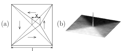
In this paper we investigate the current- and field-driven gyroscopic motion of magnetic vortices in square thin-film elements of size and thickness as shown in Fig. 1 and present a method to distinguish between spin torque and Oersted field driven magnetization dynamics. In the presence of a spin-polarized current the time evolution of the magnetization is given by the extended Landau-Lifshitz-Gilbert equation
| (1) |
with the coupling constant between the current and the magnetization where is the spin polarization, the saturation magnetization, and the degree of non-adiabaticity. Zhang and Li (2004) If the vortex keeps its static structure, its motion with the velocity can be described using the Thiele equation. Thiele (1974) This equation was expanded by Nakatani et al. Nakatani et al. (2003) to include the action of a spin-polarized current flowing in the sample,
| (2) |
Denoting the out-of-plane angle of the magnetization with and the angle of the in-plane magnetization with , the force due to the external and the stray field is
| (3) |
The gyrovector
| (4) |
indicates the axis of precession and points out-of-plane. The dissipation tensor is given by
| (5) |
It is diagonal with
| (6) |
The constant is the lower bound of the integration. It is in the order of magnitude of the radius of the vortex core. Wachowiak et al. (2002); Huber (1982); He et al. (2006); Guslienko et al. (2005) A polarization of () denotes that the magnetization in the vortex core is parallel (antiparallel) to the -axis. The velocity of the vortex core is in-plane and hence perpendicular to the gyrovector. Thus Eq. (2) can be rewritten as
| (7) |
By calculating from Eq. (7) and inserting the result in Eq. (2) we can derive the velocity
| (8) |
of the vortex core. As for any square-symmetric confining potential, the stray-field energy for small deflections can be modeled as a parabolic potential
| (9) |
with the coordinates and of the vortex core (see Fig. 1a).
In the following a spacially homogeneous current in -direction is investigated. Due to possible inhomogeneities in real samples the current flow may vary in the out-of-plane direction. This results in an in-plane Oersted field which is perpendicular to the direction of the current flow. In the following this Oersted field is accounted for by a homogeneous magnetic field in -direction. Both driving forces may depend on time. To estimate the Zeeman energy due to the Oersted field , the magnetization pattern is divided into four triangles (see Fig. 1a). Assuming that the magnetization is uniform in each of these triangles the total Zeeman energy is given by
| (10) |
with the chirality of the vortex. A chirality of () denotes a counterclockwise (clockwise) curling of the magnetization around the vortex core. We will see that this simple approximation describes the field-induced vortex motion sufficiently well. In this case the force is given by
| (11) |
Inserting Eq. (11) in Eq. (8) yields the equation of motion for the vortex. In the absence of current and field the excited vortex performs an exponentially damped spiral rotation around its equilibrium position with its free frequency
| (12) |
and the damping constant
| (13) |
From Eqs. (12) and (13) one easily obtains that
| (14) |
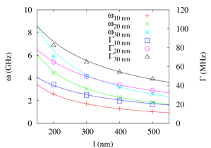
For thin-film systems () the resonance frequency of a vortex is proportional to the inverse lateral dimension . Guslienko et al. (2002) Here, we obtain from Eq. (14) that the damping constant also has a characteristic length dependence, . Substituting using Eq. (14) the equation of motion of the vortex can be written as
| (15) |
In the following we assume harmonic excitations, i.e., the magnetic field and the electrical current are of the form and . The magnetic (Oersted) field and the electrical current are in phase. Assuming that the squared Gilbert damping is small (), the damping constant of the vortex is small compared to its frequency (). Then Eq. (15) has the solution
| (16) |
with and . The first two terms with prefactors A and B are exponentially damped and depend on the starting configuration. Independent of the source of excitation, i.e., field or current, the sense of rotation of the vortex is given by its polarization, i.e., () denotes a counterclockwise (clockwise) rotation of the vortex core. Changing the sign of the chirality has the same effect as turning the magnetic field by . Similar to the motion of magnetic domain walls in thin nanowires Krüger et al. (2007) the vortex is driven by the current and the magnetic field as well as by their time derivatives.
At resonance the amplitude of the vortex core displacement in - and -direction is the same and the vortex performs a circular rotation. A vortex which is excited with a non-resonant frequency has an elliptic trajectory. The ratio between the semi-axes is given by the ratio between the frequency of the excitation and the resonance frequency.
To test the applicability of the approximations leading to the analytical result in Eq. (16) we performed micromagnetic simulations for magnetic thin-film elements with different lengths, thicknesses, polarizations, and chiralities. The material parameters of permalloy are used, i.e., an exchange constant of J/m and a saturation magnetization of A/m. For the Gilbert damping we use a value of which is in the regime as found by recent experiments. Nibarger et al. (2003); Schneider et al. (2005); Liu et al. (2007) The degree of non-adiabaticity is chosen to be equal to . Meier et al. (2007); Hayashi et al. (2006)
For the micromagnetic simulations we extended the implementation of the Landau-Lifshitz-Gilbert equation in the Object Oriented Micro Magnetic Framework (OOMMF) by the additional current-dependent terms of Eq. (1). OOM ; Krüger et al. (2007) The simulation cells are 2 nm in - and -direction which is well below the exchange length of permalloy. One cell of thickness was used in -direction. As in the analytical model we substitute the Oersted field by a homogeneous magnetic field.
At first the four ground states with and are calculated for each and . The ground states are then excited by a short current pulse. The frequency and the damping constant are obtained by fitting the subsequent free oscillation with the first two terms in Eq. (16). Results are presented in Fig. 2 and exhibit a good agreement between the analytical model and the micromagnetic simulations. not
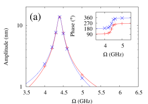
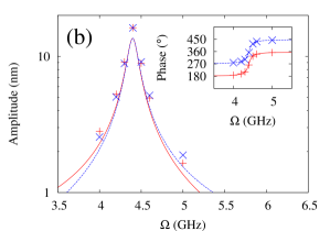
For the driven oscillation we choose a magnetic film element with length nm and thickness nm. This system size allows for reasonable computing time. The magnetization is excited with harmonic currents with a spin-polarized current density A/m2 in -direction. The field excitation was performed with a harmonic field of A/m in -direction. The amplitudes and the phases of the oscillation in - and -direction of a vortex with positive polarization and chirality are depicted in Fig. 3. In the current-driven oscillation an excellent accordance between analytical calculations and numerical simulations is found. In the field-driven case the amplitudes of the analytical solution are smaller than the amplitudes obtained from the micromagnetic simulations. These deviations are caused by the differences between the approximate magnetization depicted in Fig. 1 and the exact state. The phases between the maximum of the exciting magnetic field and the maximum deflection in - and -direction agree very well. Vortices with other polarization and chirality (not shown) yield the same accordance. Yam
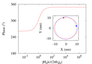
From Eq. (16) one can see that the current and field induced forces on the vortex are of the same form. For experiments it is important to separate the Oersted-field and the spin-torque driven case. We describe the ratio between the field and current-induced forces on the vortex by , i.e., a mixing angle of and denote the fully spin-torque driven and the fully field-driven case, respectively. There are two possibilities to determine the ratio of both forces. On the one hand for non-resonant excitations the trajectory of the vortex core is elliptical as illustrated in Fig. 4. According to Eq. (16) the direction of the major axis of the ellipse is determined by . The amplitude of the vortex motion decreases very fast when the excitation frequency deviates from resonance, i.e., for experimental observation very high current densities with frequencies close to resonance are needed. On the other hand the excitation mechanisms can be distinguished using the phase of the vortex deflection. Bolte et al. As indicated by the dots in Fig. 4 the position of the vortex at maximum current depends on , which can be determined from Eq. (16). The latter method is also applicable with excitations at resonance frequency.
In conclusion we derived an analytical expression for the current- and field-driven trajectory of a vortex in thin-film elements. The analytical result is compared to micromagnetic simulations. The accordance between both approaches is very good. The analytical expression enables us to determine the ratio between spin torque and Oersted field driven motion.
Acknowledgements.
Financial support by the Deutsche Forschungsgemeinschaft via SFB 668 ”Magnetismus vom Einzelatom zur Nanostruktur” and via Graduiertenkolleg 1286 ”Functional metal-semiconductor hybrid systems” is gratefully acknowledged.References
- Berger (1996) L. Berger, Phys. Rev. B 54, 9353 (1996).
- Slonczewski (1996) J. Slonczewski, J. Magn. Magn. Mater. 159, L1 (1996).
- Wachowiak et al. (2002) A. Wachowiak et al., Science 298, 577 (2002).
- Shinjo et al. (2000) T. Shinjo et al., Science 289, 930 (2000).
- Choe et al. (2004) S.-B. Choe et al., Science 304, 420 (2004).
- Van Waeyenberge et al. (2006) B. Van Waeyenberge et al., Nature 444, 461 (2006).
- Shibata et al. (2006) J. Shibata et al., Phys. Rev. B 73, 020403(R) (2006).
- Stoll et al. (2004) H. Stoll et al., Appl. Phys. Lett. 84, 3328 (2004).
- Guslienko et al. (2006) K. Y. Guslienko et al., Phys. Rev. Lett. 96, 067205 (2006).
- Raabe et al. (2005) J. Raabe et al., Phys. Rev. Lett. 94, 217204 (2005).
- Meier et al. (2007) G. Meier et al., Phys. Rev. Lett. 98, 187202 (2007).
- Kläui et al. (2005) M. Kläui et al., Phys. Rev. Lett. 94, 106601 (2005).
- He et al. (2006) J. He et al., Phys. Rev. B 73, 184408 (2006).
- (14) M. Bolte et al., unpublished.
- Zhang and Li (2004) S. Zhang and Z. Li, Phys. Rev. Lett. 93, 127204 (2004).
- Thiele (1974) A. A. Thiele, J. Appl. Phys. 45, 377 (1974).
- Nakatani et al. (2003) Y. Nakatani et al., Nature Materials 2, 521 (2003).
- Huber (1982) D. L. Huber, Phys. Rev. B 26, 3758 (1982).
- Guslienko et al. (2005) K. Y. Guslienko et al., Phys. Rev. B 71, 144407 (2005).
- Guslienko et al. (2002) K. Y. Guslienko et al., J. Appl. Phys 91, 8037 (2002).
- Krüger et al. (2007) B. Krüger et al., Phys. Rev. B 75, 054421 (2007).
- Nibarger et al. (2003) J. Nibarger et al., Appl. Phys. Lett. 82, 2112 (2003).
- Schneider et al. (2005) M. Schneider et al., Appl. Phys. Lett. 87, 072509 (2005).
- Liu et al. (2007) Z. Liu et al., Phys. Rev. Lett. 98, 087201 (2007).
- Hayashi et al. (2006) M. Hayashi et al., Phys. Rev. Lett. 96, 197207 (2006).
- (26) OOMMF User’s Guide, Version 1.0 M.J. Donahue and D.G. Porter Interagency Report NISTIR 6376, National Institute of Standards and Technology, Gaithersburg, MD (Sept 1999) (http://math.nist.gov/oommf/).
- (27) Note: is a fit parameter. The values used are 8.85 nm, 11.66 nm, and 13.59 nm for film thicknesses of 10 nm, 20 nm, and 30 nm, respectively.
- (28) During the preparation of this manuscript a publication of Yamada et al. Yamada et al. (2007) came to our attention that contains first steps towards the inclusion of spin-polarized currents into the dynamics of vortices, however without consideration of the phase and the excentricity of the vortex motion.
- Yamada et al. (2007) K. Yamada et al., Nature Materials 6, 269 (2007).