Particle Tracking with a Thin Pixel Telescope
Abstract
We report results on a tracking performance study performed using a beam telescope made of 50 m-thick CMOS pixel sensors on the 1.5 GeV electron beam at the LBNL ALS.
1 The Thin Pixel Prototype Telescope
The anticipated ILC physics program indicates that identification of heavy fermions with high efficiency and purity is of primary importance. The requirements in terms of track extrapolation accuracy are . The Vertex Tracker design and the sensor R&D is driven by this requirement. CMOS pixel sensors are an attractive option for the ILC Vertex Tracker. In particular, they can be back-thinned to 50 m or less, without significant performance deterioration [1].
While there has already been some experience with the reconstruction of well-isolated, high momentum particles with monolithic pixel sensors [2, 3], no data exists on low momentum particle tracking with thin pixel sensors with occupancy conditions comparable to those expected at the ILC. We present here results obtained with a Thin Pixel Prototype Telescope (TPPT) on the 1.5 GeV beam at the LBNL Advanced Light Source (ALS) accelerator complex. The TPPT is the first beam telescope made of thinned CMOS pixel sensors. It consists of three planes of thin pixel sensors (layers 1 to 3), each spaced by 17 mm. One additional detector (layer 4) is added 17 mm downstream of the third layer. The MIMOSA 5 chip [4, 5], developed at IPHC in Strasbourg, France, has been selected for the TPPT. This chip, fabricated in the 0.6 m AMS process, features a large active area of 1.71.7 cm2 and more than 1 M pixels. The epitaxial layer is 14 m thick and the pixel pitch 17 m.One sector of each MIMOSA 5 chip, corresponding to a 510512 pixel array, is readout through a custom FPGA-driven acquisition board. The beam spill consists of a single bunch with a repetition rate of 1 Hz and the extraction signal is used as a trigger. For each spill we acquire three frames, one before the particles arrive on the TPPT. Four 14 bits, 40 MSample/s ADCs simultaneously read the four sensors, while an array of digital buffers drive all the required clocks and synchronisation signals. A 32 bits wide bus connects the FPGA to a digital acquisition board installed on a control PC. Data is processed on-line to perform correlated double sampling, pedestal subtraction, noise computation and cluster identification. To reduce the amount of data written to disk only the addresses and pulse heights of the pixels in a fixed matrix around the centre of a cluster candidate are recorded. The data is then converted in the lcio format and the offline analysis is performed by processors developed within the Marlin framework [6]. Each event is scanned for pixels with pulse height over a signal-to-noise (S/N) threshold of 4.5, these are designated as cluster ‘seeds’. Seeds are then sorted according to their pulse height values and the surrounding, neighbouring pixels are tested for addition to the cluster. Pixels with a pulse height in excess to 2.0 time the noise are accepted. The neighbour search is performed in a 55 matrix. Clusters are not allowed to overlap and we require that clusters are not discontinuous, i.e. pixels associated to a cluster cannot be interleaved by any pixel below the neighbour threshold. The point of impact of the particle track on the detector is determined by reconstructing the charge centre-of-gravity of the cluster.
2 The ALS Beam Test with 1.5 GeV Electrons
The TPPT telescope is operated in an optical enclosure mounted on an optical rail and aligned on the ALS BTF beam line. We report here results of the first data taking performed in Fall 2006. The temperature was kept constant during operation at 27∘C by forced airflow. The cluster S/N averaged on the TPPT layers is 14.5. Due to a drop of the voltage supplied to the chip, one of the planes of the telescope was not fully efficient during the ALS data taking. Because of that we also accept particle tracks reconstructed on two layers, provided they have a hit on the reference plane within 150 m.
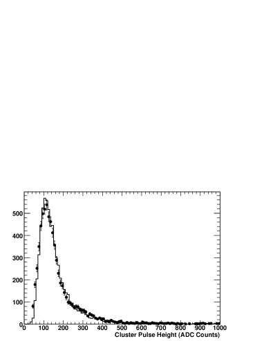
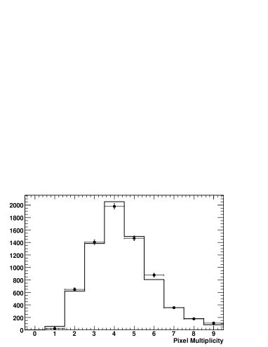
Detailed simulation of the TPPT has been carried out, using the Geant-4 package [7] to generate the particle points of impact and energy deposits on the sensitive planes. These have been stored in lcio format and used as input to a CMOS pixel simulation program implemented in Marlin [8]. Noise values have been matched to those measured for the detectors in the telescope. Digitised simulation has been passed through the same cluster reconstruction program as the real data and reconstructed hits used to fit straight particle tracks, after pattern recognition. The single detector response is well reproduced by the simulation. Figure 1 compares the cluster pulse height and the pixels multiplicity in a cluster for simulation and ALS beam test data.
The TPPT at the ALS beam-line allows us to perform detailed studies of particle tracking with various, controllable, levels of track density under realistic conditions. Data have been collected at the BTS with different beam intensities ranging from 0.5 particles mm-2 up to about 5 particles mm-2. These particle densities resemble those expected in the core of hadronic jets at = 500 GeV. In particular, the distribution of the distance between a hit associated to a particle track and its closest hit reconstructed on the same layer in the high intensity runs at the ALS reproduces that predicted by simulation for for = 120 GeV at 500 GeV.
After data taking, the beam telescope geometry has been surveyed using an optical metrology machine. The results of this survey have been used as starting point of the alignment procedure, performed on a sample of approximately 20000 well-isolated particle tracks with four correlated hits. After alignment, track candidates have been defined by matching hits on two layers. Each track candidate has been extrapolated to the third layer, where the closest hit has been added, if its residual was less than 50 m. Pattern recognition ambiguities have been solved based on the number of associated hits and on the difference between the track slope and the expected beam slope, determined from the settings of the beam-line final dipoles. Tracks have then been re-fitted using a modified least-square, to account for kinks due to multiple scattering on the measuring planes [9] and extrapolated to the reference layer, where the residual to the closest reconstructed hit has been computed. Since the beam contains a fraction of lower momentum particles, which increases moving away from the beam axis, only the central region of the beam was used and an additional cut was imposed on the residual on the second coordinate.
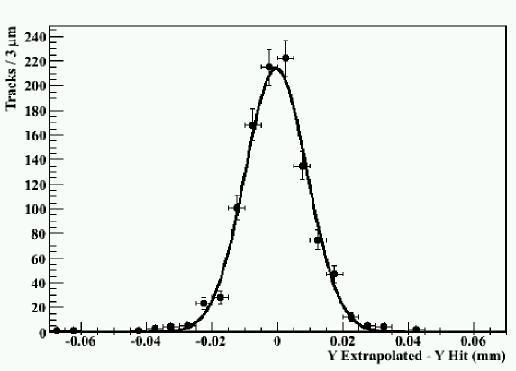
The tracking performance has been characterised by the residuals between the extrapolation of a track reconstructed using at least two layers and the point reconstructed on the reference layer using two different geometries. The first uses the extrapolation of the track back to the first layer. This resembles closely the case of track extrapolation from the vertex detector to the interaction point. Using all accepted tracks we measure a residual of (9.40.2) m (see Figure 2), which becomes (8.90.4) m when restricting to three-hit tracks. This should be compared to 6.8 m obtained from the simulation, which assumes perfect geometry. Subtracting in quadrature the estimated single point resolution of x m, we obtain an extrapolation resolution of 8.5 m for a 1.5 GeV particle, which is consistent with the impact parameter resolution required for the ILC. The second geometry adopted extrapolates the track on the second detector layer. In this case the multiple scattering effect is reduced by having measurements on both side of the extrapolation plane and we measure a residual of (6.90.1) m.
Despite the multiple scattering effect, the extrapolation resolution of the TPPT at the ALS is significantly smaller than the MIMOSA-5 pixel pitch. This allows to perform studies of cluster shape as a function of the track point of impact. We compared the number of pixels, along the horizontal coordinate, in clusters reconstructed on the first layer which are associated to two sets of tracks. In the first set tracks with extrapolation along the horizontal axis within 4 m from the pixel centre are chosen: the average pixel multiplicity is 1.5. In the second set the track intercepts the detector more than 8 m away from the pixel centre: the average pixel multiplicity increases to 2.3.
3 The T-966 Telescope
A second thin pixel telescope (TPPT-2) has been built for use in the T-966 beam test experiment of the 120 GeV proton beam at the Fermilab MTest facility. The TPPT-2 consists of four layers of 50 m-thin MIMOSA-5 sensors mounted on new mezzanine cards with low profile components and larger clear region in the PC board below chip. The four layers are mounted using precision mechanics and are spaced by 15 mm. The chips have been positioned on the mezzanine boards using a precision vacuum chuck which gives a mounting accuracy better than 50 m. Downstream from the TPPT-2, a detector under test (DUT) can be mounted on a computer-controlled XY stage which allows to remotely align it to the telescope. The DUT spacing from the TPPT-2 can be varied from 5 mm to 20 mm. The TPPT-2 has been tested in May 2007 on a 1.23 GeV beam extracted from the ALS. An average S/N of 15.5 has been measured operating at 27∘C. For the first T-966 data taking, planned for July and August 2007, an operating temperature of 20∘C is foreseen, which will reduce the noise.
Acknowledgements
This work was supported by the Director, Office of Science, of the U.S. Department of Energy under Contract No.DE-AC02-05CH11231 and used resources of the National Energy Research Scientific Computing Center, supported under Contract No.DE-AC03-76SF00098. We are indebted to the staff of the LBNL Advanced Light Source for their help and the excellent performance of the machine.
References
- [1] M. Battaglia, D. Contarato, P. Giubilato, L. Greiner, L. Glesener and B. Hooberman, Nucl. Instrum. Meth. A 579 (2007) 675 [arXiv:physics/0611081].
- [2] S. Stanic et al., Nucl. Instrum. Meth. A 568 (2006) 181.
- [3] M. Trimpl et al., Nucl. Instrum. Meth. A 568 (2006) 201.
- [4] Yu. Gornushkin et al., Nucl. Instrum. and Meth. A A 513 (2003), 291.
- [5] G. Deptuch, Nucl. Instrum. and Meth. , A 543 (2005) 537.
- [6] F. Gaede, Nucl. Instrum. Meth. A 559 (2006) 177.
- [7] S. Agostinelli et al., Nucl. Instrum. Meth. A 506 (2003), 250.
- [8] M. Battaglia, Nucl. Instrum. Meth. A 572 (2007) 274.
- [9] G. Lutz, Nucl. Instrum. Meth. A 273 (1988) 349.