Focal Plane Instrumentation of VERITAS
Abstract
VERITAS is a new atmospheric Cherenkov imaging telescope array to detect very high energy gamma rays above 100 GeV. The array is located in southern Arizona, USA, at an altitude of 1268m above sea level. The array consists of four 12-m telescopes of Davies-Cotton design and structurally resembling the Whipple 10-m telescope. The four focal plane instruments are equipped with high-resolution (499 pixels) fast photo-multiplier-tube (PMT) cameras covering a 3.5 degree field of view with 0.15 degree pixel separation. Light concentrators reduce the dead-space between PMTs to 25 and shield the PMTs from ambient light. The PMTs are connected to high-speed preamplifiers allowing operation at modest anode current and giving good single photoelectron peaks in situ. Electronics in the focus box provides real-time monitoring of the anode currents for each pixel and ambient environmental conditions. A charge injection subsystem installed in the focus box allows daytime testing of the trigger and data acquisition system by injecting pulses of variable amplitude and length directly into the photomultiplier preamplifiers. A brief description of the full VERITAS focal plane instrument is given in this paper.
1 Introduction
VERITAS (Very Energetic Radiation Imaging Telescope Array System) is a successor of the pioneer imaging atmospheric Cherenkov telescope (IACT), the Whipple 10-m telescope that was used to discover TeV emission from a number of galactic and extra-galactic objects including the Crab Nebula [1], the “standard candle” in TeV astronomy. The array consists of four telescopes giving stereoscopic views of showers, significantly increasing gamma-ray flux sensitivity, angular resolution and energy resolution relative to the stand-alone Whipple telescope. To fully realize the capabilities of the four VERITAS telescopes, each is equipped with a low-noise, high-resolution focal-plane instrument coupled to a fast FADC-based data-acquisition system housed in a nearby trailer. The trigger system for the array has three tiers as described elsewhere [2] [3].
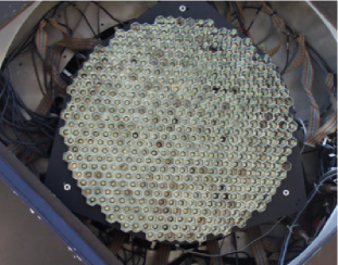
Each camera has 499 photomultiplier (PMT) pixels spanning a total aperture of 3.5∘ with 0.15∘ pixel spacing. Figure 1 shows the camera face with the light concentrator plate (see below) installed. The pixels are supported by a hexapod structure, allowing precise adjustment of the position and tilt of the focal plane. The camera is designed to operate at a trigger level of only 4 photoelectrons in the presence of night-sky noise, the dominant background. The relative electronic background is reduced through the use of low-noise preamplifiers in the base of the PMTs that boost the signal before it travels to the data-acquisition electronics in the nearby trailers. Because of this preamplification, the PMTs can be operated with reduced high voltage, that allows the array to be operated during partial moon night without damage to the PMTs. The remainder of this paper gives a brief description of each of the instrument components and its performance.
2 Photomultipliers and Preamplifiers
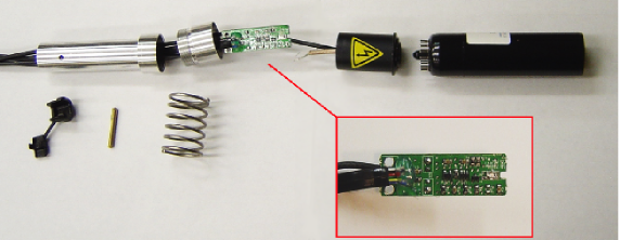
Figure 2 shows the main components of a VERITAS pixel. The photon sensors are Photonis XP2970/02 29mm diameter PMTs with 10 gain stages, currently operated at a gain of . These have a typical quantum efficiency about 25 at wavelengths relevant for Cherenkov images (about 320 nm).
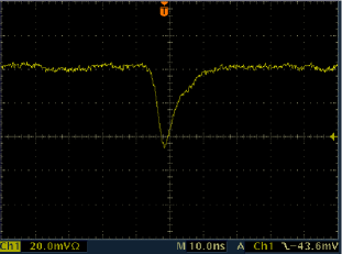
As illustrated in the blowup in the figure, a custom-built preamplifier is installed in each PMT base. The main purpose of the preamplifier is to boost the signal before its journey through cables to the FADC’s in the electronics trailer, thereby improving the ratio of signal to electronic noise. The preamplifier has a bandwidth of 300 MHz, in order to reproduce pulse shapes for fast Cherenkov pulse rise time ns (Figure 3) and good low-frequency response, preserving signal shapes down to 21 kHz. Under normal operating conditions, the PMT gain combined with the preamplifier amplification factor of 6.6 gives a single photoelectron pulse height of 2.4 mV after 140 ft of coaxial cable (RG-59) and a dynamic range of 0 to -2.2 V matched to the input of the FADC-based data-acquisition system. The preamplifier also provides a direct DC output for anode-current monitoring purposes as described in the next section.
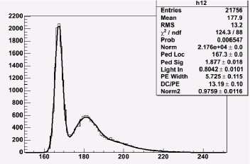
With this quiet system we can recognize single photoelectron peaks under standard operation conditions. However, to obtain well-defined single photoelectron peaks for more accurate calibration, we normally increase the gain by a factor of 3 as shown in Figure 4 where the single photoelectron peak is clearly visible at just over 180 digital counts.
By modifying the mechanical and electrical connections between PMTs and bases, and by testing and selection, we have obtained a percentage greater than 99 of fully functional installed pixels.
3 Current Monitor Subsystem
It is important to monitor PMT anode currents in real time to protect the tubes from transient light sources such as bright stars moving through a tube’s field of view or lights near the telescope accidentally turned on. It is also important in detecting long-term changes in tube performance. This is accomplished with custom-designed electronics inside the camera box connected to electronics in the adjacent trailer through a fiber-optic link.
Inside the camera box there are 16 FPGA-controlled circuit boards daisy chained via a fast serial bus.111The design of these Field Programmable Gate Array (FPGA) boards is patented and the number of boards can be expanded up to 256. US Patent No. 6,717,514. Each board has 32 identical input channels multiplexed to one of the four 8-bit FADCs222Note that this FADC is not the FADC in the data-acquisition chain. operating at 50 MHz. The output is 1 digital count per 0.5 A giving a dynamic range of 0 to 127 A. Each of the channels can be used for reading and transmitting either PMT anode currents or environmental sensor outputs.
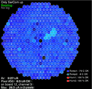
The channels are read, displayed and recorded by a computer in the electronics trailer (Figure 5). If the anode current of a PMT exceeds a preset threshold, the PMT voltage is automatically reduced.
4 Charge Injection Subsystem
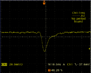
This subsystem, installed inside the camera box, allows testing and calibration the full data-acquisition chain following the PMTs. This is particularly convenient for working on the data-acquisition system under non-observing conditions, e.g., during the day. The subsystem consists of a central charge injection circuit board inside each camera that is fanned out to individual PMT channels. The charge injection circuit utilizes a programmable pulse generator (PPG) that generates pulses (Figure 6) with an adjustable frequency ranging from 1 Hz to 1 MHz. The pulse height can be varied by 85dB, and the output pulse width is also adjustable from 1 ns to 10 ms. The generator is connected to fanout/mask boards attached to each of the 16 current monitor boards.
The fanout/mask boards direct the pulses to particular pixels selected by the operator. The subsystem can then be used for detailed studies of triggering efficiency using different triggering patterns, crosstalk, diagnostics to find mis-wired/mislabeled channels and the ability to inject pseudo-Cherenkov images into the electronics system.
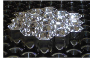
5 Light Concentrators
A light concentrator plate is installed on each camera to reduce dead
space between PMTs increasing signal light collection and to limit
the acceptance angle of the pixels to the solid angle subtended by
the telescope thereby reducing background light. It consists of 499
molded plastic cones glued onto a machined Delrin plate. (Figure
7 shows a small group of light cones sitting on the
plate.) The inner surface of each cone has an evaporated aluminum
coating with a protective overlayer 333The coating is done by
Evaporated Coatings, Inc. (ECI) with coating 801p.
(http://www.evaporatedcoatings.com/) giving greater than reflectivity above 260 nm. The cone shape is a hybrid design with
a hexagonal entrance window evolving to a Winston cone at the exit.
The effect of the cones is to increase the geometrical light
collection efficiency at the photocathodes from 55 to 75 [4].
6 Acknowledgements
VERITAS is supported by grants from the U.S. Department of Energy, the U.S. National Science Foundation and the Smithsonian Institution, by NSERC in Canada, by PPARC in the U.K. and by Science Foundation Ireland. The authors also acknowledge support from Iowa State University.
References
- [1] Weekes, T. C. et al. Observation of TeV gamma rays from the Crab nebula using the atmospheric Cerenkov imaging technique. Astrophysical Journal 342, 379–395 (1989).
- [2] Holder, J. Exploiting VERITAS Timing Information. In 29th International Cosmic Ray Conference, Pune (2005).
- [3] Holder, J. et al. The first VERITAS telescope. Astroparticle Physics 25, 391–401 (2006).
- [4] Jordan, P. & Krennrich, F. The Design of Light Concentrators for a 12 m Čherenkov Telescope. http://cherenkov.physics.iastate.edu/ (2004).