Waveguiding power of photonic crystal slabs
Abstract
We consider the waveguiding by thin patterned slabs embedded in a homogeneous medium. In the longwave limit, the wave spectra of slabs are found to be well described by a single frequency-independent parameter, which we call the “guiding power”. The guiding power can be evaluated in an effective medium approximation, similar to the Maxwell Garnett theory, but modified for the local field corrections specific to the two-dimensional geometry. The guiding power is different for the transverse magnetic (TM) and transverse electric (TE) polarizations. We show that the confinement factor of TM waves in a porous layer with high index ratio can exceed that for a homogeneous layer. Similarly enhanced confinement of TM waves is demonstrated for a layer of elongated cylinders or elliptic inclusion with a high axis length ratio. The effect originates from the suppression of local field effects and the increasing internal field in the inclusion. It may be useful in the design of far-infrared or THz quantum cascade lasers.
pacs:
42.70.Qs, 42.79.Gn, 41.20.Jb, 42.25.Lc, 78.66.QnI Introduction. Guiding power
Waveguiding of light in layered patterned structures, such as slabs of two-dimensionally periodic photonic crystals (2D PC), has attracted much interest in view of potential photonic applications Yablonov ; Painter ; Joannop . The studied 2D patterns include periodic lattices of deep etched air pores or “conjugate” lattices of high permittivity cylinders. The patterned slabs (not necessarily periodic) can be employed in waveguides as either a core or a cladding. Numerous theoretical computations of the band spectra of 2D PC and PC slabs have been reported, based on expansions of the electromagnetic field in plane waves Maradu ; Joannop or cylindrical waves Nicoro ; Ohtaka , as well as based on finite-difference time-domain methods TafLove ; Borodit .
The low-frequency region of electromagnetic waves in the 2D PC is well understood. The waves have a linear spectrum that is very close to that obtained in the effective media approximation Sarychev ; Halevi with an effective permittivity corresponding to the Maxwell Garnett theory Sarychev ; Nicoro2 . This means that when the wavelength exceeds the structure period , the optical properties are primarily determined by the filling factor of the inclusions (i.e. their total volume fraction) and do not rely on their long-range order or their shape variation. The disorder leads to a weak (for ) Rayleigh-like scattering.
In this paper we investigate the waveguiding by PC slabs in a long wavelength frequency range, , where is the wave vector, is the thickness of the active or a core layer of the waveguide. We show that in this range the waveguiding has a universal form described by a single parameter, which we call the “guiding power”. For short-period structures, , and for sparse structures, , it can be calculated in terms of the polarizability of the patterned dielectric core via a self-consistent procedure to include local field effects.
We discuss the waveguiding in highly inhomogeneous structures, such as planar regular arrangements of nearly overlapping cylindrical pores or high-index cylindrical rods with large spacings. For thin slabs, the local field effects are different from those in an infinitely extended 2D PC, primarily because of the short-range dipolar interaction between the finite-height cylinders or spheres. Proper inclusion of the local field effects in the low-frequency region enables a perturbative approach with fast convergence.
In the design of far-infrared and terahertz semiconductor lasers the optical confinement is an important issue. It poses a severe problem for quantum cascade lasers where intersubband radiative transitions require transverse magnetic (TM) polarization of emitted waves Capasso . With this polarization in the long wavelength region, the so-called modal confinement factor is known to be small for any contrast of the dielectric constants between the core and the claddings Marcuse ; Visser . The reason for the small values of is the reduced electric field in the high-index core due to the boundary conditions at the core layer surface. The decrease of the electric field devalues traditional attempts to improve waveguiding by choosing cladding layers with lower index.
In this paper, we propose to enhance the confinement by using penetration of the electric field into a patterned core. The model core under consideration comprises additional cylinder inclusions of high dielectric constant compared to that of the claddings. The filling factor for these inclusions is small, so as not to disturb processes in the active region (which is the remainder of the core outside the inclusions). We show that the better penetration of the field can result in a much stronger waveguiding (much reduced field spread outside the layer), as compared to the homogeneous layer. This case has an advantage of not being critically sensitive to the composition of the claddings.
An alternative way to improve the guiding of TM waves is to use a porous PC slab as the active layer. We show that the confinement of TM modes in a structure with a high index contrast (typical for silicon-on-insulator devices) can be enlarged if the active layer has a patterned structure with pores. Even though the average index of the porous core is reduced, this is more than compensated by better penetration of the electric field into the structure, so that the wave confinement is ultimately enhanced.
Patterned structures with the enhanced confinement can be advantageously used in the laser design to minimize the losses from free-carrier absorption and reduce the threshold current.
II Weakly guided waves in laterally uniform waveguides
In order to introduce the concept of weak waveguiding, let us first consider the propagation of an electromagnetic wave along a laterally uniform dielectric waveguide with a core layer. Let the index profile depend only on , approaching at large the (background) dielectric constant of the cladding layers.
Two wave polarizations are distinguished by the field orientation relative to the structure symmetry plane. Consider the case of a TE mode, when the electric field has only an in-plane component and is strictly perpendicular to the wave propagation direction . The wave equation for the electric field is of the form
| (1) |
where is the 2D wave vector in the plane of the waveguide. Let us integrate Eq. (1) between and , that is over the region where the permittivity is variable. At the solution of the Eq. (1) has the form and we get
| (2) |
In the limit of weak waveguiding, , the field is a slowly varying function across the entire layer. Therefore it can be replaced in the integral by a constant value taken, e.g., at . Outside the guiding layer we have and hence in Eq. (2) we can take as the zeroth-order approximation. This yields
| (3) |
We have replaced the limits of integration by , since the region where does not contribute to the integral in Eq. (3).
Similar arguments can be used to consider the waveguiding of TM waves, when the only non-vanishing component of the magnetic field is . For this case, in the long wavelength limit, the quantity that remains a smoothly varying function across the layer is the normal component of the electric displacement vector . Integrating the wave equation for we obtain
| (4) |
For both polarizations the dispersion relation for the guided wave is of the form
| (5) |
where is the frequency parameter. Parameter describing the exponential decay of the wave away from the core, , depends on frequency. Since the spectrum of the guided wave in the long-wavelength limit has a universal character. It is convenient to introduce another parameter ,
| (6) |
which we shall call the “guiding power” of the high-index core. The value of defined by Eq. (6) is owing to the fact that it is frequency-independent in the weak guiding limit, Marcuse . So long as is constant, Eqs. (5, 6) define a universal dispersion relation for the guided modes of a three-layer dielectric waveguide of core thickness .
According to Eqs. (3) and (4), the guiding power is given by :
| (7) |
For the simplest case of a constant permittivity () core layer, Eqs. (7) reduce to
| (8) |
In structures with a low index contrast, , the values of for both modes are small and close to each other. In the opposite limit, , the guiding power for the TM mode is times weaker than , which can be explained by the reduced component of the electric field inside the slab.
Confinement of guided waves is usually described by the dimensionless “confinement factor” (fraction of the wave intensity that flows in the high-index core). Quite generally, is proportional to the guiding power. The condition corresponds to the weak guiding limit. In this limit the guiding power determines both the confinement properties and the dispersion of waves.
III Waveguiding by a PC slab
Consider now the electromagnetic wave propagation along a photonic crystal slab formed either by a lattice of holes in a core layer or by a “mirror” structure with a set of cylinder rods serving as the core. In the long wavelength limit , where is the PC lattice constant and is the layer thickness, the field inhomogeneity is important only at short distances away from the slab, since the short-range components of the fields decay exponentially over the distances of order . This allows us to identify the polarized waves as TE-like and TM-like. For the weakly bound guided waves have a smooth exponential decay of the wave field away from the core, with . The relationship between and can be obtained either by integrating the wave equation using the weak-guiding approximation (as in the preceding section) with averaging in the lateral plane, or by using the effective media approach. The latter corresponds to replacing the PC layer by a homogeneous slab with an effective (anisotropic) dielectric constant ASSL . Equations (5, 6) remain valid in both cases, but the guiding power must now be evaluated taking account of the polarizability of the laterally inhomogeneous guiding layer.
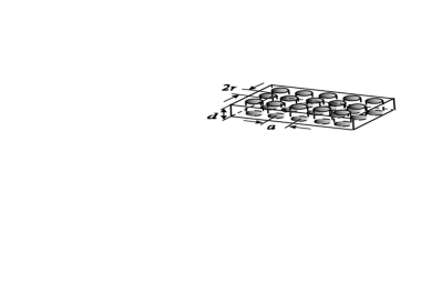
Consider a core comprising a set of dielectric cylinders of radius with the dielectric constant and height . The cylinders are spaced apart with a lattice constant and the core medium between the cylinders is assumed to have the same permittivity as the background. To compare the results with those of full-scale calculations, we further consider a square lattice of cylinders and the structure parameters close to those studied in Johnson1 ; Johnson2 .
Importantly, the polarizability of a single cylinder is highly anisotropic. For a sufficiently elongated cylinder, , the polarization vector inside the cylinder is homogeneous and equal to that of an ellipsoid with a high axes length ratio. Besides, one must allow for depolarization effects. We take them into account approximately, by replacing the cylinders by prolate ellipsoids with the same diameter and the same volume, so that the axes length ratio of the ellipsoid . The dipole moment of a single cylinder in an external electric field equals , where is the cylinder volume and the polarizability of a single cylinder is given by
| (9) |
Here is the depolarization factor L&L8 . Even though in our case , the product cannot be neglected. The average dielectric function of the layer equals
| (10) |
The guiding power can now be calculated as in Eq. (8),
| (11) |
and is given by
| (12) |
The spectrum of the TE mode can be calculated in a similar way, with the transverse layer polarizability, , expressed in terms of the transverse polarizability of a single cylinder, . The result is similar to Eq. (9) except for the depolarization factor, which should now be replaced by . For a highly elongated cylinder, is very close to 0.5, so that
| (13) |
In calculating the average dielectric function of the layer one should take into account the local field effects (enhancement of the local field due to the field of surrounding cylinders). The simplest way to do this is to use the Maxwell Garnett approach, which is strictly applicable for . In this approximation we have
| (14) |
The guiding power for TE waves is then given by
| (15) |
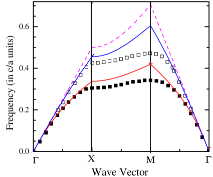
The calculated spectra of TM and TE modes in the “guiding power” approximation are shown in Fig. 1 for a square lattice structure with , , , and (). The results are compared with those of full-scale numerical calculations Johnson1 . Our spectra shown in Fig. 1 do not include the effect of Bragg reflection, which can be allowed for by using a perturbative approach Sakoda . With Bragg reflections included SPIE , the guiding-power spectra approach the exact curves very closely.
Note that the guiding-power spectra are described by one parameter for each mode. We can determine the values of these parameters by a best fit to the exact curves. In units, the best-fit parameters are and . These values can then be compared with those directly calculated from Eqs. (12,15), giving and . For TE waves, the Maxwell Garnett approximation apparently overestimates the local field effects. If we use the polarizability of separate cylinders, we find , which is closer to the best fit.
For the TM mode, which is of practical importance for intersubband lasers and is our main interest in this paper, the calculated value provides an excellent approximation. We regard this very good agreement as a justification for applying the guiding power approach to calculations of the confinement factor. Note that due to the layer anisotropy, the waveguiding for TM waves is much stronger than that for TE waves.
Consider now the waveguiding in structures with a porous core layer. To calculate the guiding power for TM waves in this case, we use again Eq. (11). However, the depolarization effects are now very different. As is well known L&L8 , these effects are important when the high-permittivity component has a convex shape, as is the case for cylinders. In contrast, for the cylindrical holes, the effect of depolarization can be essentially neglected, due to the concave shape of the high-permittivity component. Hence is given by
| (16) |
where the fraction of high-polarizability material in the core equals for a film of porosity . The resultant TM-wave guiding power is of the form
| (17) |
To calculate the guiding power for TE waves, we again use the Maxwell Garnett approximation, noting, however, that it is strictly applicable only for thick enough guiding layers, (this restriction is, of course, compatible with required for the validity of the guiding power approximation). For a porous layer we find
| (18) |
whence the guiding power for TE waves is of the form
| (19) |
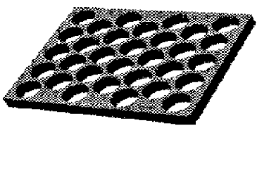
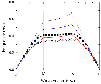
To check these results against those of full-scale numerical calculations Johnson1 , we used Eqs. (5, 6) to calculate the TE and TM wave spectra for a triangular lattice of pores with , and (the porosity 0.734), see Fig. 2. The values of in units that give best fit to the spectra are and . The values calculated from Eqs. (17,19) are and . As expected, the spectrum of the TM guided wave is well described with an average dielectric constant of the core layer over most of the Brillouin zone up to the zone boundary, where it is strongly modified by the Bragg reflection. The Bragg reflection can be allowed using a perturbative approach Sakoda ; SPIE . For a high-porosity layer of fairly small thickness, the spectrum of TE waves is also described by the guiding power approach, but the value of is overestimated in the Maxwell Garnett approximation.
Note that both TM and TE waves remain weakly guided even in the extreme limit of sparse structures, , so long as SPIE .
IV Confinement factor of TM waves by a PC slab
The modal gain in a three-layer slab waveguide with an active core layer (ACL) of thickness can be expressed as a product of the material gain, and the dimensionless “optical confinement factor”, . For weakly guided TE waves with a smooth variation of the electric field of the wave across the layer, the confinement factor is just proportional to the guiding power, . For TM waves the confinement is influenced by the weakening of the electric field in the high-permittivity core. Generally, it can be written in the form Visser
| (20) |
where the integral in the numerator is taken over the active region. For a homogeneous core layer one can calculate the confinement factor explicitly. In the case of weak guiding, , using Eq. (20) and the boundary condition for the normal component of the field at the core edge planes, we find
| (21) |
The value of is smaller than by a factor . For a given core composition (i.e. for a fixed value of ) and as a function of the cladding-layers index, has a maximum value,
| (22) |
achieved when the ratio of the dielectric constants is . Note that is about ten times smaller than the confinement of the TE mode achievable in the same structure. For a fixed value of , the factor does not have a maximum, except at , where . The difference in confinement factors is negligible in the structures with very small index contrast and thus very small confinement factors for both waves ASSL .
In the preceding section we showed that the TM waveguiding can be enhanced and even can exceed that for the TE mode by incorporating in the core layer cylindrical rods of high polarizability. We shall now show that the mode confinement in the active part of the core layer can be enhanced as well.
Consider the waveguiding in a patterned structure with initially small difference between the dielectric constant of the active layer (denoted by ) and that of the cladding background, . Small values of are typical for quantum cascade lasers with a multilayer active region Capasso . To enhance the waveguiding, we incorporate in the structure a set of cylindrical rods of radius , lattice constant , and dielectric constant . (Although we speak of the “lattice constant”, the periodicity of rods is of no importance here and the result can be expressed in terms of their fill factor .)

For a waveguide with a patterned core layer, we first use the average dielectric constant to estimate the average field (which is somewhat different from the local field), and then use Eq. (20) to calculate the confinement factor of guided TM waves
| (23) |
It can be seen from Eq. (23) that in structures with a high ratio , the enhancement of waveguiding with due to the increasing factor can overwhelm at small both the decrease in and the decreasing factor that describes reduction of the electric field in the active layer.
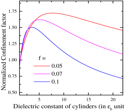
The variation of the confinement factor, calculated with Eq. (10) [modified to include a term proportional to ()] and Eq. (23), is plotted in Fig. 3. The increase of confinement with is mainly due to the guiding power enhanced by the better polarizability of cylinders, hence it is most effective at small . It can be seen from Eqs. (23) and (10) that the increase of confinement with takes place only provided and . Note, that the increase of with towards the optimum value should be evaluated at fixed and (we have used and ). This gives . For the optimum filling factor is small, , and the factor is close to unity. In this most favorable case, the resulting confinement factor is larger than that for the initial homogeneous structure and approaches the optimal value given by Eq. (22).
The dependence of the confinement factor on the cylinder dielectric constant for is shown in Fig. 4. In terms of the cylinder polarizability (Eq. 9), the enhancement of confinement is well pronounced for , which can be achieved in the low-wavelength limit by inclusions of extremely highly-polarizable materials.
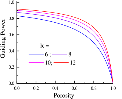
Next we consider the waveguiding in structures with a porous core layer. As seen from Eqs. (17), the guiding power of a porous active layer is smaller than that of a homogeneous layer for any ratio and is decreasing with . However, for large the decrease is small, while the rise of the electric field with the layer porosity provides an enhancement of the TM wave confinement.
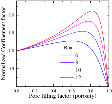
Variations of the guiding power and the confinement factor with the porosity for several values of the ratio are shown in Fig. 5. For a given , the maximum value of is achieved at
| (24) |
Hence, replacing the homogeneous layer by a porous layer can increase the modal gain only using materials with 3. The maximum value of is
| (25) |
where is the confinement factor for a homogeneous core layer of the same . As seen from Eq. (25), the increase of confinement by porosity can be tangible only for structures with large . For Si/SiO2 structures with the maximal confinement enhancement is achieved at , but it is not very large (1.28); for the enhancement is 2.1.
We remark that although the numerical values above can be determined more accurately with more elaborate numerical calculations, the increase of confinement by patterning initially homogeneous layers is an exact result for waveguide structures with a high enough index contrast between the core and the claddings. The result is based solely on the power-law dependencies of the guiding parameter and the field ratio inside the active layer.
V conclusions
In conclusion, we considered the polarization-dependent waveguiding of light by thin highly inhomogeneous slabs embedded in a uniform medium. We examined exemplary slab structures comprising a monolayer of patterned cylindrical pores etched in a active core layer or a pattern of high-index dielectric rods (cylinders), embedded in the core layer. We demonstrated that for an optimal choice of the patterned layer structure an increase of optical confinement of TM wave is possible compared to a homogeneous layer. This increase can be achieved both by incorporating sparsely separated high-index rods which promote electric field penetration in the patterned structure and by using high-porosity core layers. Our results can be useful in the design of quantum cascade lasers.
References
- (1) E. Yablonovitch, T. J. Gmitter and K. M. Leung, “Photonic band structure: The face-centered-cubic case employing nonspherical atoms,” Phys. Rev. Lett. 67, 2295 (1991).
- (2) O. Painter, R. K. Lee, A. Scherer, A. Yariv, J. D. O’Brien, P. D. Dapkus, and I. Kim, “Two-dimensional photonic band-gap defect mode laser,” Science, 284, 1819 (1999).
- (3) J. D. Joannopoulos, R. D. Meade and J. N. Winn, Photonic Crystals: Molding the Flow of Light, Princeton University, Princeton, NJ, 1995.
- (4) M. Plihal and A. A. Maradudin, “Photonic band structure of two-dimensional systems: The triangular lattice,” Phys. Rev. B44, 8565 (1991); V. Kuzmyak, A. A. Maradudin and A. R. McGurn, “Photonic band structure of two-dimensional systems fabricated from rods of a cubic polar crystal,” ibid. 55, 4298 (1997).
- (5) N. A. Nicorovici, R. C. McPhedran and L. C. Botten, “Photonic band gaps for arrays of perfectly conducting cylinders,” Phys. Rev. E52, 1135 (1995).
- (6) K. Ohtaka, T. Ueta and K. Amemiya, “Calculation of photonic bands using vector cylindrical waves and reflectivity of light for an array of dielectric rods,” Phys. Rev. B57, 2550 (1998).
- (7) A. Taflove, Computational Electrodynamics – The Finite-Difference Time-Domain Method, Artech House, Boston, MA, 1995.
- (8) M. Boroditsky, R. Coccioli and E. Yablonovitch, “Analysis of photonic crystals fir light emitting diodes using the finite difference time domain technique,” Photonics West, 1998.
- (9) A. K. Sarychev and V. M. Shalaev, “Electromagnetic field fluctuations and optical nonlinearities in metal-dielectric composites,” Phys. Rep. 335, 275 (2000).
- (10) A. A. Krokhin, P. Halevi and J. Arriaga, “Long-wavelength limit (homogenization) for two-dimensional photonic crystals,” Phys. Rev. B65, 115208 (2002).
- (11) N. A. Nicorovici, R. C. McPhedran and L. C. Botten, “Photonic band gaps: noncommuting limits and the ”acoustic band,” Phys. Rev. Lett. 75, pp. 1507–1520, 1995. Phys. Rev. Lett. 75, 1507, 1995.
- (12) O. Malis, C. Gmachl, D. L. Sivco, L. N. Pfeiffer, A. M. Sergent, and K. W. West, “The quantum cascade laser: A versatile high-power semiconductor laser for mid-infrared applications,” Bell Labs Tech. Journ. 10, # 3, 199 (2005).
- (13) D. Marcuse, Theory of Dielectric Optical Waveguides, Academic Press, Boston, 1991.
- (14) T. D. Visser, H. Blok, B. Demeulenaere, and D. Lenstra, “Confinement factors and gain in optical amplifiers,” IEEE J. Quant. Electron. 33, 1763 (1997).
- (15) S. Johnson, S. Fan, P. R. Villeneuve, J. D. Joannopoulos, and L. A. Kolodziejski, “Guided modes in photonic crystal slabs”, Phys. Rev. B60, 5751 (1999).
- (16) S. Johnson, P. R. Villeneuve, S. Fan, and J. D. Joannopoulos, “Linear waveguides in photonic-crystal slabs”, Phys. Rev. B62, 8212 (2000).
- (17) A. V. Subashiev and S. Luryi, “Modal control in semiconductor optical waveguides with uniaxially patterned layers,” IEEE J. Lightwave Techn. 24,1513 (2006).
- (18) S. Luryi and A. V. Subashiev, “Waveguides with uniaxially patterned layers” Proc. of SPIE 6127, 612705 (2006); online at http://www.ee.sunysb.edu/~serge/212.pdf .
- (19) T. Ochiai and K. Sakoda, “ Nearly free-photon approximation for two-dimensional photonic crystal slab”, Phys. Rev. B64, 045108 (2001).
- (20) L.D. Landau and E.M. Lifshitz, Electrodynamics of Continuous Media, Pergamon Press, Oxford, 1960.