Laser Atmospheric Studies with VERITAS
Abstract
As a calibrated laser pulse propagates through the atmosphere, the amount of Rayleigh-scattered light arriving at the VERITAS telescopes can be calculated precisely. This technique was originally developed for the absolute calibration of ultra-high-energy cosmic-ray fluorescence telescopes but is also applicable to imaging atmospheric Cherenkov telescopes (IACTs) [5]. In this paper, we present two nights of laser data taken with the laser at various distances away from the VERITAS telescopes and compare it to Rayleigh scattering simulations.
1 Introduction
VERITAS, the Very Energetic Radiation Imaging Telescope Array System, is a GeV-TeV gamma-ray telescope array located at the Fred Lawrence Whipple Observatory on Mount Hopkins in Southern Arizona. It is an array of four 12m reflectors arranged in a slanted trapezoid with baselines ranging from 35m to 109m. Each telescope has a camera comprising 499 photomultiplier tubes (PMTs) arranged in a hexagonal lattice and a field of view of . The PMTs are read out via flash-ADCs (FADCs) at a rate of 500 Msamples/s. For details see [4].
Standard calibration of IACTs is usually done through measurements of the efficiency and gain of individual elements such as electronics and PMTs, and through muon-ring measurements. VERITAS also uses diffused laser light for relative calibration [2]. However, scattered light from a calibrated laser pulse arriving at the telescopes can be detected and simulated accurately, allowing absolute calibration to be reliable and simple.
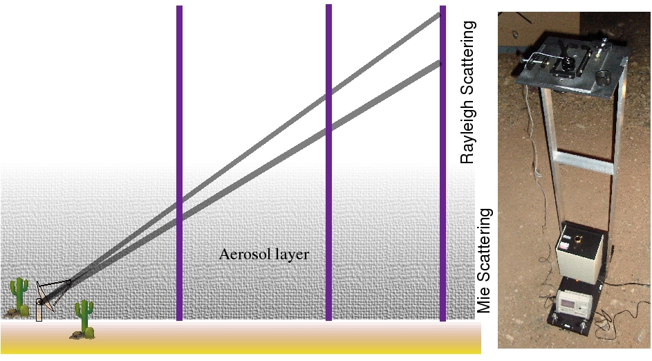
The nitrogen laser used has a wavelength of 337nm and is mounted on a movable rack for easy transport. It is also equipped with flexible beam collimation and intensity adjustment. The laser is fired pointing at zenith with the telescopes pointing at in elevation. As the laser shot travels upward through the atmosphere, the laser light undergoes Rayleigh and Mie scattering, some of which is detected by the telescopes. Depending on how far away the laser is fired, the telescopes may intercept the scattered light from an altitude that is within the aerosol layer. Inside the aerosol layer, the amount of scattered light increases due to Mie scattering. Mie scattering might even dominate over Rayleigh scattering at these close distances (see figure 1). With measurements at different distances, we can compare them to the Rayleigh-scattering simulation and determine how thick and dense the aerosol layer was on that particular night. Furthermore, we can conclude on the absolute calibration of individual telescopes once enough data over several nights has been collected.
2 Observations
The laser measurements presented here were taken in fall 2006, when only two of the four telescopes were installed and operating. On Oct 22 and Nov 24 of 2006, we took the nitrogen laser to distances between 1 and 7 km away from the telescopes. Both the laser and the telescopes were forced to trigger synchronously by two external GPS clocks such that all recorded events contain the laser shot. At the beginning and the end of each 5-minute run, we recorded the ground temperature and pressure at the laser firing site for Rayleigh simulation purposes.
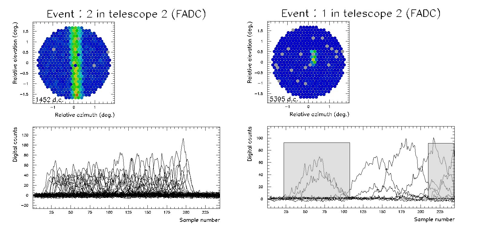
Data acquisition of the telescopes was tuned to record 244 FADC samples (488 ns) so that each event records the laser shot for as long as the data acquisition would allow. As the laser fires at farther distances, the telescopes look at a longer section of the laser beam (see figure 1). Due to the limit of recording time in data acquisition and geometric effects, the number of pixels that recorded the laser decreases with distance.
3 Analysis
Using an analysis package similar to those described in [1], we convolved the FADC trace of each pixel with a box-like function to sum the laser pulse. The width of the box function is adjustable to ensure the entire laser pulse is summed since the width of the laser pulse increases with distance (see figure 2). The telescopes intercept a longer section of the laser beam at farther distances, hence each pixel records a longer laser pulse. The rest of the samples are averaged and used for pedestal subtraction. To avoid using a truncated pulse, the peak of each pulse used in our analysis has to be at least half of the box function width away from the first and last recorded samples. After the cutoffs and the convolution are done, we apply a gain-matching factor to the total signal of each pixel such that the laser pulse recorded by the pixels is uniform.
Simulations of the VERITAS telescopes’ response [3] were performed together with the Rayleigh-scattering simulation program [5], and the same analysis described above was applied to the simulated response. Figure 3 displays the ratio between the real data and the Rayleigh-scattering simulation.
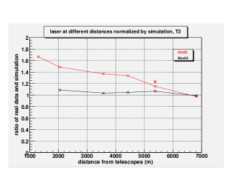
The gain in the simulation is from the single-photoelectron measurement described in [2]. We adjusted the telescopes light collection efficiency such that the Rayleigh simulation matches the real data where Rayleigh scattering dominates. This provides the absolute calibration of telescopes. In the November data set the ratio of real data and simulation is close to 1 in all distances, indicating our Rayleigh simulation matches the real data closely at all distances and minimal amount of Mie scattering occured. In October, the curve steepens at closer distances, suggesting a thicker aerosol layer than in November.
4 Conclusion
At closer distances, the telescopes intercept the laser beam inside the aerosol layer and were more strongly affected by Mie scattering. At farther distances, the telescopes intercept the laser beam above the aerosol layer and Rayleigh scattering dominates. As shown in figure 3, the amount of light received from the laser at 1 km away is nearly doubled of the Rayleigh simulation, whereas at farther distances, the Rayleigh simulation matches the real data and the curve flattens. The thickness of the aerosol layer changes the distance where the curve plateaus and how steep the curve gets at close distances. With enough data sets from farther distances where Rayleigh simulation matches real data, the simulation parameters used could determine the absolute calibration of individual telescopes, which could then be used to reduce systematic errors in the energy reconstruction of gamma-ray showers.
The aerosol layer changes every night and attenuates Cherenkov showers at an unknown level. A laser study could help determine the nightly aerosol attenuation by having a laser setup at a close location and at a distant location. Taking a set of laser measurements prior to observing, the data-simulation comparison curve could give information on the aerosol attenuation factor, which could then be applied to analysis.
The data acquisition setup for these laser measurements greatly limits the pixel statistics at farther distances. At 1 km away from the telescopes, over 50 pixels passed our truncation cut, while at 6 km away, less than 10 pixels passed the cuts. The systematic uncertainty in farther measurements are much greater than in closer measurements. The next step is to configure the pixels to read at different memory depths of the recorded trace such that all pixels aligned with the image of the scattered beam will contain the laser pulse and become usable, alleviating our pixel-statistic problem.
Acknowledgments
This research is supported by grants from the U.S. Department of Energy, the U.S. National Science Foundation and the Smithsonian Institution, by NSERC in Canada, by PPARC in the U.K. and by Science Foundation Ireland .
References
- [1] M. Daniel et al. The VERITAS Standard Data Analysis. In 30th ICRC, Merida, 2007.
- [2] D. Hanna et al. Calibration techniques for VERITAS. In 30th ICRC, Merida, 2007.
- [3] G. Maier et al. Monte Carlo studies of VERITAS. In 30th ICRC, Merida, 2007.
- [4] G. Maier et al. VERITAS: Status and Latest Results. In 30th ICRC, Merida, 2007.
- [5] N. Shepherd et al. Absolute calibration of imaging atmospheric Cherenkov telescopes. In 29th ICRC, Pune, pages 427–430, 2005.