Capillary-Driven Instability of Immiscible Fluid Interfaces Flowing in Parallel in Porous Media
Abstract
When immiscible wetting and non-wetting fluids move in parallel in a porous medium, an instability may occur at sufficiently high capillary numbers so that interfaces between the fluids initially held in place by the porous medium are mobilized. A boundary zone containing bubbles of both fluids evolve which has a well defined thickness. This zone moves at constant average speed towards the non-wetting fluid. A diffusive current of bubbles of non-wetting fluid into the wetting fluid is set up.
pacs:
47.20.Ft,47.56.+r,47.54.-r,89.75.FbWhen a fluid displaces another one in a porous medium the interface separating the two fluids may become unstable. In the case of two-phase immiscible displacement, local capillary barriers on pore-scale levels affect the behavior on larger scales, and it turns out that there is an extraordinary richness to the ways instabilities occur and how the separating interface subsequently develops. Depending on several flow properties like viscosity ratio, wetting properties with respect to the porous medium and how fast the displacement occurs, a wide range of behaviors are found in both drainage and imbibition ranging from pure invasion percolation to viscous fingering d92 ; s95 . A huge effort has gone into classifying and understanding this rich behavior, both from a fundamental scientific point of view, but also due to its importance in a number of very important fields ranging from oil recovery, to spreading of pollutants in the ground water, to problems related to sequestering.
It is then surprising to discover that the related problem of immiscible fluids flowing in parallel to the interface between them rather than normal to it in a porous medium, has received very little attention in comparison. Such parallel flow is e.g. seen in connection with fully developed viscous fingers zy92 and in connection with flow in stratified reservoirs cda71 ; yl81 ; zl81 ; f88 ; fn88 . When the flow rate is low so that capillary forces dominate at the interface, the parallel interface is stable and each phase behaves as in a single-phase flow system. Nevertheless, it has been recognized that above a certain threshold in the flow-rate, but where capillary forces still dominate, imbibition processes become important in the evolution of the interface and hence the crossflow of the immiscible fluids. However, at larger flow rates, where viscous forces dominate, shear-driven Kelvin-Helmholtz type instabilities are believed to occur b82 ; pb02 ; me04 . Both theoretical and experimental work has been invested in studying the Kelvin-Helmholtz instability in vertical Hele-Shaw cells zy92 ; gr97 ; grrsw97 , as it provides a model for parallel flow in porous media in the viscous regime.
It is the aim of this Letter to investigate the instability that occurs at the interface between two immiscible fluids flowing in parallel in a regime where capillary effects cannot be ignored. This regime has remained essentially untouched in the literature. We find that above a threshold flow rate and with a viscosity ratio between the two fluids favoring the formation of viscous fingers, the interface becomes unstable, and a boundary zone appears containing intermixed bubbles of both fluids. This boundary zone has a well-defined width and moves at constant average speed towards the non-wetting fluid. A diffusive current of bubbles of non-wetting fluid into the wetting fluid is set up, but the situation of bubbles of wetting fluid entering the non-wetting fluid is absent.
This instability may prove to be an important mechanism for mixing non-wetting fluid into wetting fluid. A practical application may be CO2 sequestering in porous rock formations. The less wetting gas is blown into the porous medium which is already saturated by a more wetting fluid. A mixing zone will then form at the boundary between the gas and the fluid where gas bubbles will be generated. These bubbles are then transported into the wetting fluid where they eventually are absorbed.
We study this instability here using a two-dimensional network simulator first developed by Aker et al. amhb98 with later extensions by Knudsen et al. kah02 and Ramstad and Hansen rh06 . The network forms a square lattice oriented at 45∘ with respect to the overall flow direction. Each link forms an hour-glass shaped tube. Disorder is introduced in the model by having the average tube radii be drawn from a flat distribution on the interval , where is the link length. Capillary pressure in the links is caused by the presence of interfaces in them.
As the tubes are hour glass shaped, the capillary pressure difference caused by a meniscus at position , the distance from one of the two nodes it is attached to, is given by .
We assume cylindrical tubes so that the flow rate in a tube is given by the Hagen-Poiseulle relation from laminar flow
| (1) |
where is the pressure difference between the nodes connected by the tube. The effective viscosity is the volume-weighted average of the viscosities of the fluids contained in the tube. The sum runs over the number of meniscii in the tube. We accept up to 10 meniscii in any given tube. If this number is exceeded or the distance between two bubbles is too small, we merge the mensicii.
The flow equations are solved by assuming flux conservation at each node, i.e., invoking the Kirchhoff equations. This is done by defining a pressure at each node. We use the conjugate gradient method for this bh88 . After the node pressures have been determined, the positions of the meniscii are integrated forwards by an adaptive time-step so that no single meniscus movement exceeds one tenth of a tube-length . When meniscii reach the ends of a tube, they are moved into the other eligible tubes connected to that node. For details, see kah02 .
The flow of the two fluids in the network is controlled by the ratio between capillary and viscous forces at the pore level and quantified through the capillary number
| (2) |
where is the largest viscosity of the two immiscible fluids, is the cross-sectional area of the network and is the total flux through this area.
Besides the capillary number, the ratio between the viscosities of the two fluids forms the second dimensionless number to control the flow,
| (3) |
We set in the following. Hence, there is initially no pronounced shear in the flow patterns in the network.
We implement periodic boundary conditions in the average flow direction kah02 ; rh06 . This implies that the flow configurations sees no boundaries in the flow direction, and the fluid configurations may develop over large times and distances. There is no periodicity in the direction normal to the average flow direction. The boundaries parallel to the average flow direction are in contact with a reservoir of either wetting or non-wetting fluid. A constant pressure drop is set up across the network in the average flow direction, causing the total flux .
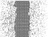
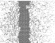
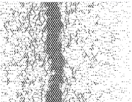

The network is prepared with either a band of non-wetting fluid parallel to the average flow direction, surrounded by wetting fluid or vice versa. Hence, the saturation of non-wetting fluid, and wetting fluid, is non-uniform. We show in Fig. 1 the network initially prepared with a band of non-wetting fluid in the middle. If the pressure drop is too small, the interfaces in the tubes forming the boundaries between the two fluid types will be stabilized by the capillary pressures and the boundaries are stable. However, when the pressure difference is above a minimal value so that the initial capillary number , the boundaries destabilize and the system evolves.
(a)
(b)
(c)
Early in the evolution of the system, fingers of non-wetting fluid form when the viscosity ratio between the two fluids allow this. This is a signature of unstable non-wetting front propagation in the viscous regime. The fingers are bent in the direction of the average flow. Due to the flow typically being at an angle compared to the fingers, they are susceptible to break up. The broken off fingers form bubbles that migrate into the wetting fluid, and consequently the wetting fluid also migrates into the non-wetting fluid. This is due to the appearance of an effective pressure gradient normal to the average flow direction across the boundary region between the two fluids. This gradient is in turn due to the appearance of a gradient in the effective permeability. The effective pressure gradient leads to imbibition of the wetting fluid into the non-wetting region. This process creates a compact front and a saturation profile moving in the direction normal to the average flow direction, resembling that of Buckley-Leverett flow s95 .
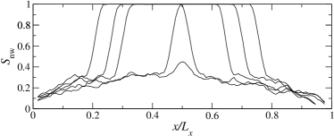
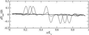
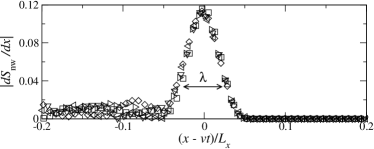
There is a length scale associated with the saturation profile. We define it through the width of the bell-shaped non-wetting saturation gradient as shown in Fig. 2 based on an average over five samples. From the motion of the two maxima of along the -axis, which is the direction normal to the average flow direction, we determine the mean velocity of the non-wetting saturation profile. The data collapse shown in Fig. 2c, where is plotted against , shows that the mean velocity of the profile is constant and the shape of the profile is also constant. The length scale is for this system . Hence, unlike the Kelvin-Helmholz shear instability, the interfacial instability between two different fluids in a porous medium proceeds through the creation of a well-defined saturation profile characterized by a length scale and an average speed which remains constant.
The shape of the non-wetting saturation profile corresponds to a there being a boundary region where bubbles are created. This boundary region moves into the non-wetting zone. There are no bubbles migrating into this zone ahead of the moving boundary region. On the other side, there is a diffusion current of bubbles of non-wetting fluid into the wetting zone. The diffusing bubbles stem from the non-wetting fingers that break off due to the average flow being at an angle with respect to the fingers.
When the two approaching boundary regions eventually meet, the middle non-wetting band is destroyed as shown in the last picture of the sequence shown in Fig. 1.
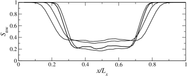
We now reverse the initial configuration so that a band of wetting fluid is surrounded by non-wetting fluid. We show in Fig. 3 the evolution of the non-wetting saturation profile as a function of time. As before, boundary regions where bubbles form are created. However, after some initial time, they stabilize and do not move. This is in sharp contrast to the previous situation where the boundary regions move with constant mean velocity. This is caused by there being no bubble transport outside the boundary region and into the non-wetting region. Inside the wetting band, there is diffusive bubble transport, but as the width of the band is finite and it is surrounded by bubble-generating boundary regions on both sides, the net diffusive current stabilizes at zero.
We consider in the following the evolution of the total flow rate as the system evolves for both configurations we have studied. We consider first the case of a non-wetting fluid band surrounded by wetting fluid. As the flow is sustained by a constant pressure drop across the network in the average flow direction, , the total flow rate will at all times be proportional to the permeability of the network. We show in Fig. 4 the evolution of the total flow rate as a function of time for networks initially prepared with a non-wetting band in the middle and with a wetting band in the middle. We analyze first the case when the networks starts with a non-wetting band in the middle. The evolution of for two different pressure drops are shown in Fig. 4. We see that for both pressure drops, decreases linearly in time after an initial transient. In the case of the larger pressure drop, the red curve, the flow rate starts increasing again reaching essentially the flow rate it had initially. This behavior can be understood as follows. After the initial transient and before the rapid increase of in the high- case, the system consists of three zones: (1) a non-wetting zone characterized by an effective local permeability , (2) a boundary zone characterized by a local permeability and (3) a zone where non-wetting fluid forms diffusing bubbles in the wetting fluid. The local permeability here is . If the width of the non-wetting zone is , of the boundary zone is and of the mixed zone is , then the total permeability of the network is given by
| (4) |
As the boundary regions moves with constant average speed , we have that and since , it follows that . Inserting these two equations in Eq. (4) gives
| (5) |
Since the viscositities of the two fluids are equal, . As is larger than , the total flow rate falls off with time.
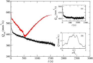
Fig. 4 shows that at a larger pressure difference, the total flow rate starts increasing again after the linear regime we have just described. This is due to the non-wetting band in the middle having been depleted and the non-wetting bubbles are diffusing out of the network. Then the network is being depleted of non-wetting fluid and hence interfaces which lowers the effective permeability. The opposite situation, a middle wetting band, is shown in inset (a) in Fig. 4. We see that the total flow rate saturates, indicating that the system enters a steady state as already discussed in connection with Fig. 3.
We have in our numerical experiments kept the pressure difference across the network constant. If we rather had kept the total flow rate constant, the instability that sets in when will be much more violent. This is so since the pressure drop will increase to keep , leading in turn to an acceleration of the boundary region.
In this Letter we have investigated the stability where two different fluid flow parallel to each other. We find that under constant pressure conditions, for a sufficiently high capillary number a boundary region develops with a well-defined width when the viscosity ratio between the two fluids favor the formation of viscous fingers. This region, which essentially is foam, moves at a constant average speed into the non-wetting region. On the wetting side, a diffusive current of non-wetting bubbles away from the boundary zone develops. It would be of great interest to see this instability reproduced in the laboratory, e.g. in two-dimensional glass-bead filled Hele-Shaw cells.
We acknowledge very interesting and useful discussions with E. G. Flekkøy, H. A. Knudsen, K. J. Måløy and P.-E. Øren. This work has been supported by Norwegian Research Council Grant No. 154535/432. A. H. thanks Numerical Rocks AS for their hospitality.
References
- (1) F. A. L. Dullien, Porous Media: Fluid Transport and Pore Structure, Second Edition (Academic Press, San Diego, 1992).
- (2) M. Sahimi, Flow and Transport in Porous Media and Fractured Rock (VCH, Weinheim, 1995). See chapter 12 for a comprehensive review of instabilities of immiscible displacement.
- (3) M. Zeybek and Y. C. Yortsos, J. Fluid Mech. 241, 421 (1992).
- (4) K. R. Coats, J. R. Dempsey and J. H. Anderson, Soc. Petrol. Engrs. J. 11, 63 (1971).
- (5) Y. Yokoyama and L. W. Lake, SPE 10109 (1981).
- (6) V. J. Zapata and W. L. Lake, SPE10111 (1981).
- (7) F. J. Fayers, Soc. Petrol. Engrs. Reservoir Engng. 3, 311 (1988).
- (8) F. J. Fayers and T. M. J. Newley, Soc. Petrol. Engrs. Reservoir Engng. 3, 542 (1988).
- (9) H. H. Bau, Phys. Fluids 25, 1719, (1982).
- (10) M. Panfilov and M. Buès, J. Fluid. Mech. 473, 59 (2002).
- (11) G. M. Moatimid and Y. O. El-Dib, Physica A 333, 41 (2004).
- (12) P. Gondret and M. Rabaud, Phys. Fluids, 9, 3267 (1997).
- (13) P. Gondret, N. Rakotomalala, M. Rabaud, D. Salin and P. Watzky, Phys. Fluids, 9, 1841 (1997).
- (14) E. Aker, K. J. Måløy, A. Hansen and G. G. Batrouni, Transp. Por. Media 32, 163 (1998).
- (15) H. A. Knudsen, E. Aker and A. Hansen, Transp. Por. Media, 47, 99 (2002).
- (16) T. Ramstad and A. Hansen, Phys. Rev. E 73, 026306 (2006).
- (17) G. G. Batrouni and A. Hansen, J. Stat. Phys. 52, 747 (1988).