A design principle for improved 3D AC electro-osmotic pumps
Abstract
Three-dimensional (3D) AC electro-osmotic (ACEO) pumps have recently been developed that are much faster and more robust than previous planar designs. The basic idea is to create a “fluid conveyor belt” by placing opposing ACEO slip velocities at different heights. Current designs involve electrodes with electroplated steps, whose heights have been optimized in simulations and experiments. Here, we consider changing the boundary conditions—rather than the geometry—and predict that flow rates can be further doubled by fabricating 3D features with non-polarizable materials. This amplifies the fluid conveyor belt by removing opposing flows on the vertical surfaces, and it increases the slip velocities which drive the flow.
pacs:
47.57.jd, 47.61.Fg, 82.47.Wx, 82.45.-hI Introduction
Microfluidic pumps are crucial components of lab-on-a-chip systems. There is growing interest in exploiting various phenomena of induced-charge electro-osmosis (ICEO) Bazant and Squires (2004); Squires and Bazant (2004) due to the lack of moving parts, favorable scaling with miniaturization, tunable local flow control, and low operating voltage suitable for portable or implantable devices. The most advanced technology of this type is based on AC electro-osmosis (ACEO) around micro-electrodes. ACEO was discovered by Ramos et al. Green et al. (2000); González et al. (2000); Green et al. (2002), who described steady, time-averaged vortices over a pair of identical, co-planar electrodes applying an AC voltage. Ajdari Ajdari (2000) predicted that breaking spatial symmetry would generally lead to directional flows, and thus to microfluidic pumps. Based on this principle, the first ACEO pumps were built using arrays of asymmetric pairs of planar electrodes, according to the design of Brown, Smith, and Rennie Brown et al. (2000); Studer et al. (2004).
Motivated by ICEO flows around three-dimensional (3D) metal structures Bazant and Squires (2004); Squires and Bazant (2004); Levitan et al. (2005), Bazant and Ben Bazant and Ben (2006) recently predicted that the flow rate of ACEO pumps can be increased by more than an order of magnitude (at the same voltage and minimum feature size) by creating a “fluid conveyor belt” with arrays of non-planar electrodes. This was validated experimentally by Urbanski et al. Urbanski et al. (2006) using gold electrodes with electroplated steps. Current work has optimized the step height in simulations Olesen (2006) and experiments Urbanski et al. (2007) for this particular class of designs.
In this Rapid Communication, we predict that by modifying the boundary conditions in addition to the geometry, the fluid conveyor belt can be further amplified and the driving slip velocities increased. We begin by explaining the design principle in simple terms, building on the arguments of Bazant and Ben Bazant and Ben (2006). We then use the same simulation methods to validate the theory and predict improved robustness and doubling of the flow rate compared to current designs.
II Grooved Designs
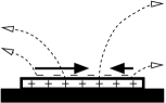
The motivation behind the discovery of 3D ACEO was to remove the competition between different slip velocities along electrode surfaces, as shown in Fig. 1. ACEO generally drives electro-osmotic slip in opposite directions along different sections of each electrode, and Ajdari’s idea is to bias this competition so that one direction “wins”. In planar pumps with asymmetric electrodes, symmetry is broken by making one electrode and one inter-electrode gap in each pair wider than the other, thus generating slightly more slip in one direction. Though directionality is achieved, a portion of each electrode is “counteracting” in the sense that its surface slip is working against the net pumping (see Figures 1 and 1).
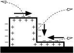
This competition is turned into cooperation in 3D ACEO pumps by raising the productive part of each electrode relative to the counteracting part. The vortices above the counteracting portions are then recessed relative to the bulk fluid. These are “rollers” in the fluid conveyor belt: their tops are moving in the direction of the pumping and are vertically aligned with the productive part of the electrode.
There is a problem with this design, however. Because the sides of the steps are polarizable, the adjacent fluid will have a significant double layer, and there will be a vertical electro-osmotic slip (see Fig. 1). This slip acts against the sides of the rollers, slowing them down and reducing the effectiveness of the net pumping (see Fig. 1).
In the spirit of Bazant and Ben (2006), we can improve performance by minimizing this new source of competition. In principle, we could eliminate the vertical slip altogether by making the sides of the steps (but not the tops) relatively non-polarizable. This should then lead to a more effective fluid conveyor belt and better overall performance (see Figures 1 and 1).


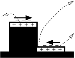

This can be achieved experimentally, for instance, by building the entire step out of a non-polarizable material and then depositing thin electrodes atop the step and in the recess. Alternatively, one might etch the recesses into the substrate rather than building the steps up from it. Regardless of the actual fabrication process, we shall henceforth refer to any system whose steps have non-polarizable sides as the “grooved” design, and the case in which the sides of the steps are polarizable as the “plated” design. Note that a grooved design was originally used to illustrate the fluid-conveyor-belt principle in the context of a fixed-potential ICEO pump Bazant and Ben (2006), but it has never been applied to 3D ACEO pumps, in simulations or experiments. All work has focused on plated designs, and the competition between vertical slip velocities has not been recognized.
We have seen how grooved designs offer greater efficiency in the sense that there is less counteractivity in the fluid flow. However, the grooved designs also offer greater forcing in the form of higher average slip velocities along the tops of the raised parts of the electrodes. This results from stronger electric fields near the top-left edges of the electrodes, which is precisely where most of the slip is generated.
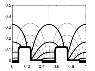
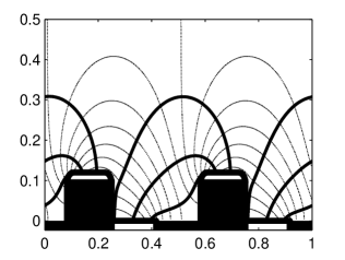
To explain these differences in the electric fields, we refer again to Figures 1 and 1. In the grooved design, the shortest distance between two electrodes is between the right edge of the recessed part of the left electrode and the left edge of the raised part of the right electrode. In the plated design, the shortest distance is much smaller as the bottom of the vertical side of the right electrode is itself part of the electrode. However, as a consequence, the important electric field lines in the plated design are longer: those starting at the left edge of the raised part of the right electrode must reach much further into the left electrode before terminating. See Fig. 3 for more complete, numerically-generated plots.
Thus the important electric fields in the grooved design are stronger because their field lines are shorter. This has another consequence for the system: the time-scale for ACEO flows is Bazant et al. (2004), where is the Debye screening length and is an ionic diffusion constant. Typically, is taken to be a characteristic length scale of the electrode geometry; however, it is really the length scale appropriate for changes in electric potential. Therefore the grooved design will have a shorter characteristic time scale, and so will operate at higher frequencies.
III Numerical Simulations
Numerical simulations allow us to test the grooved design and explore its consequences. We employ the standard low-voltage model from previous studies (e.g. Levitan et al. (2005); Bazant and Ben (2006)), using the same codebase as in Urbanski et al. (2007). As noted above, experiments have validated the use of this model to predict qualitative trends in 3D ACEO Urbanski et al. (2006, 2007), at least at low voltage and low salt concentration. To focus on the impact of boundary conditions on the side walls, we study only the simplest grooved geometry in which the electrode half-widths and inter-electrode gaps all have the same length. This is not a drastic restriction since we still achieve pumping velocities which are within a few percent of those generated by the optimal designs found by Olesen using the same model Olesen (2006).
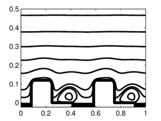
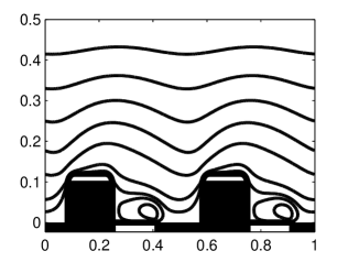
The computed streamlines for one particular case are shown in Fig. 2. The results are as predicted: the grooved design exhibits higher slip velocities, and it doesn’t suffer the strong “dip” seen in the streamlines of the plated case. This is in agreement with Figures 1 and 1.
Because moving from polarizable to non-polarizable step sides offers greater forcing and improved efficiency, it results in significantly faster pumping velocities. Indeed, for any step height, the linear model predicts that the grooved design outperforms the plated design by at least 50% (see Fig. 4). Moreover, near the optimal step heights, the grooved design has 60% stronger forcing and 20% better efficiency (defined to equal the average pumping velocity divided by the forcing), yielding pumping velocities which are almost twice as fast as the comparable plated design. This is not as dramatic as the difference between stepped and flat geometries, but it is still quite significant.
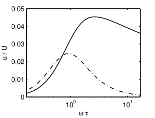
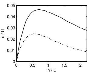
Figure 4 shows the results of two brief, parametric studies. They clearly demonstrate that across a wide range of step heights and driving frequencies, the grooved design is significantly faster. Moreover, as predicted above, we see that the ideal operating frequencies are higher in the grooved case. Indeed, when the frequency is plotted on a logarithmic scale (Fig. 4), the shorter grooved time scale causes the grooved velocity curve to be shifted to the right. This results in a crossover frequency below which the plated design is faster. However, this occurs well below the optimal frequencies, so is unlikely to be important in practice.
Figure 4 also reveals another important advantage of the grooved design: its performance curve is much less sharply peaked around its optimal operating frequency than that of the plated design. This can be explained in terms of the efficiency defined above. At high frequencies, only the double layers near the edges of the electrodes have time to charge, so these will be the only places with significant slip velocities. The left edge of the raised portions of the electrodes will still generate more positive slip in the grooved design because, as described above, the corresponding electric field lines are shorter. However, the same reasoning (and Fig. 3) allows us to conclude that the electric field lines emanating from the right edge of the recessed parts of the electrodes will be longer in the grooved case, leading to weaker negative slip. The bigger negative slips and smaller positive slips in the plated design lead to much bigger vortices which reach well above the electrodes. This impedes the bulk fluid flow, drastically reducing the efficiency. In contrast, the flow in the grooved designs look very similar at high and low frequencies. Note that this may help to reduce the poorly understood flow reversal which can sometimes be observed in plated designs Urbanski et al. (2006, 2007).
This difference in the sharpness of the performance curves suggests that the grooved design is more robust and may be less sensitive to geometric or electrical changes in operational systems. This is especially important since the physics behind ACEO is not completely understood, so our theoretical predictions for optimal geometries and driving frequencies need to be checked experimentally as in Urbanski et al. (2007).
IV Conclusion
We have predicted that altering the fabrication process for 3D ACEO pumps can have a major effect on the fluid-conveyor-belt mechanism and the driving slip velocities. In particular, designs whose 3D features have non-polarizable vertical sides should outperform those with polarizable side walls. We have explored this hypothesis numerically and have found that the grooved design could potentially double the pumping velocity of existing plated devices. The improved performance comes without having to increase the applied voltages, while at the same time being more robust to engineering and prediction errors. Our design principle could therefore have a significant impact on various lab-on-a-chip applications.
Acknowledgements.
This research was supported by the U.S. Army through the Institute for Soldier Nanotechnologies, under Contract DAAD-19-02-0002 with the U.S. Army Research Office.References
- Bazant and Squires (2004) M. Z. Bazant and T. M. Squires, Phys. Rev. Lett. 92, 066101 (2004).
- Squires and Bazant (2004) T. M. Squires and M. Z. Bazant, J. Fluid Mech. 509, 217 (2004).
- Green et al. (2000) N. G. Green, A. Ramos, A. González, H. Morgan, and A. Castellanos, Phys. Rev. E 61, 4011 (2000).
- González et al. (2000) A. González, A. Ramos, N. G. Green, A. Castellanos, and H. Morgan, Phys. Rev. E 61, 4019 (2000).
- Green et al. (2002) N. G. Green, A. Ramos, A. González, H. Morgan, and A. Castellanos, Phys. Rev. E 66, 026305 (2002).
- Ajdari (2000) A. Ajdari, Phys. Rev. E 61, R45 (2000).
- Brown et al. (2000) A. B. D. Brown, C. G. Smith, and A. R. Rennie, Phys. Rev. E 63, 016305 (2000).
- Studer et al. (2004) V. Studer, A. Pépin, Y. Chen, and A. Ajdari, Analyst 129, 944 (2004).
- Levitan et al. (2005) J. A. Levitan, S. Devasenathipathy, V. Studer, Y. Ben, T. Thorsen, T. M. Squires, and M. Z. Bazant, Colloids and Surfaces A 267, 122 (2005).
- Bazant and Ben (2006) M. Z. Bazant and Y. Ben, Lab on a Chip 6, 1455 (2006).
- Urbanski et al. (2006) J. P. Urbanski, J. A. Levitan, M. Z. Bazant, and T. Thorsen, Applied Physics Letters 89 (2006).
- Olesen (2006) L. H. Olesen, Ph.D. thesis, Technical University of Denmark (2006).
- Urbanski et al. (2007) J. P. Urbanski, J. A. Levitan, D. N. Burch, T. Thorsen, and M. Z. Bazant, Journal of Colloid and Interface Science 309 (2007).
- Bazant et al. (2004) M. Z. Bazant, K. Thornton, and A. Ajdari, Phys. Rev. E 70, 021506 (2004).