QUANTIZED VORTICES IN ATOMIC BOSE-EINSTEN CONDENSATES
Abstract
In this review, we give an overview of the experimental and theoretical advances in the physics of quantized vortices in dilute atomic-gas Bose–Einstein condensates in a trapping potential, especially focusing on experimental research activities and their theoretical interpretations. Making good use of the atom optical technique, the experiments have revealed many novel structural and dynamic properties of quantized vortices by directly visualizing vortex cores from an image of the density profiles. These results lead to a deep understanding of superfluid hydrodynamics of such systems. Typically, vortices are stabilized by a rotating potential created by a laser beam, magnetic field, and thermal gas. Finite size effects and inhomogeneity of the system, originating from the confinement by the trapping potential, yield unique vortex dynamics coupled with the collective excitations of the condensate. Measuring the frequencies of the collective modes is an accurate tool for clarifying the character of the vortex state. The topics included in this review are the mechanism of vortex formation, equilibrium properties, and dynamics of a single vortex and those of a vortex lattice in a rapidly rotating condensate.
1 Introduction
The achievement of Bose–Einstein condensation in trapped atomic gases at ultra-low temperatures has stimulated intense experimental and theoretical activity in modern physics, as seen by the award of the Nobel Prize in Physics in 2001 (Cornell 2002, Ketterle 2002). The Bose–Einstein condensate (BEC), a state of matter predicted by Einstein in 1925, is created by the condensation of a macroscopically large number of bosons into one of the eigenstates of the single-particle density matrix below the Bose–Einstein transition temperature. A remarkable consequence of the condensation is an extension of microscopic quantum phenomena into the macroscopic scale. This is an essential origin of superfluidity and superconductivity, in which macroscopically extended phase coherence allows a dissipationless current to flow.
Superfluidity is closely related to the existence of quantized vortices. For weakly interacting BECs the superfluid velocity v is given by the gradient of the phase of a “condensate wave function” with the Planck constant and particle mass . Since the wave function remains single-valued, the change in the phase around a closed contour must be an integer multiple of . Thus, the circulation around a closed contour is given by (), which shows that circulation of a vortex is “quantized” in units of . Realization of weakly-interacting atomic-gas BECs has provided an ideal testing ground to study the physics of quantized vortices; up to now, several experimental groups have reported many interesting results. This experimental work has been followed by considerable theoretical activity, leading to proposals and new problems to be tackled. (For a review of the early research stages of quantized vortices, see (Fetter 2001a).)
In this article, we review the physics of quantized vortices in atomic-gas BECs, especially focusing on the progress of the experimental research. We restrict ourselves to arguments on trapped condensates with inhomogeneous density profiles. The aim of this review is to stimulate further developments of this field. By reflecting on the history of the current research and on unresolved problems, we hope to encourage researchers in low temperature physics to investigate quantized vortices in this system. While quantized vortices have been extensively studied in the field of superfluid helium (Donnelly 1991), there has been a resurgence of interest in vortices in atomic BECs because of the following reasons. First, the diluteness of a gas yields a relatively large healing length that characterizes the vortex core size, thus enabling the visualization of vortex cores by imaging techniques characteristic of this system (see Sec.2.3). Because of this observational capability, the ability to manipulate a condensate wave function, and the tunability of the rotation over a wide range, these systems provide a unique approach to studying quantized vortices and their dynamics. Second, the finite size effect due to the trapping potential causes novel properties of vortices. Finally, multicomponent BECs provide new possibilities for studying unconventional vortex states that have been studied in other fields of physics, such as superfluid 3He, anisotropic superconductors, and theories in high-energy physics and cosmology (Volovik 2003).
Since this is the first time that the topic of atomic BECs has appeared in the Progress of Low Temperature Physics, we start with a basic introduction to ultra-cold atomic systems, including how a condensate is formed and how they are manipulated. Although it is desirable to refer to the experimental and theoretical studies of such systems in detail, we will only mention the basic ideas necessary to understand some important issues in experiment and theory because of space restrictions. These issues are described in Sec. 2. More detailed accounts can be found in the comprehensive text books by Pethick and Smith (Pethick 2002), Pitaevskii and S. Stringari (Pitaevskii 2003), and in the review paper by Leggett (Leggett 2001). In Sec. 3, we review the basic theory and experiments on quantized vortices in atomic BECs, addressing how vortices are created in this system and how they are detected. We also show the intrinsic mechanism of vortex nuclation and lattice formation in a trapped BEC. There are two interesting regimes classified by the rotation rate of the system: one at a slow rotation rate close to a critical rotation frequency where there is a single vortex, and another at high rotation rates for which a lattice of a large number of vortices is formed. The details of these two regimes are discussed in Sec. 4 and Sec. 5, respectively. Further interesting topics that cannot be explained sufficiently in this review and remaining future problems are presented in Sec. 6. We devote Sec. 7 to conclusions and outlook.
2 Introduction to ultra-cold atomic-gas BECs
While progress toward the achievement of Bose–Einstein condensation in a dilute atomic gas had proceeded for the past few decades, researchers succeeded in creating a condensate in 1995 (Anderson 1995). This realization brought great sensation in modern physics and opened a new research field combining condensed matter physics and atomic, molecular, optical (AMO) physics. Here, we briefly summarize the basic introduction about a system of ultra-cold atomic-gas BECs, giving background information for understanding the experiments and theories of quantized vortices in the following sections.
2.1 General information
A typical system considered here is a collection of neutral atoms with particle number to , trapped by a potential created by a magnetic field or an optical laser field. The density of the atomic gas is of the order of cm-3, which is lower than that of air on the earth ( cm-3). The transition temperature to Bose-Einstein condensation can be estimated from a dimensional analysis of the relevant physical quantities (, , ) as , which is in a range from nK to a few K. At such low temperatures, the gas phase cannot be a stable thermodynamic state and could in principle collapse to the solid phase. However, this relaxation is dominated by a three-body recombination process, which is a rare event for dilute and cold gases; the lifetime of the sample is thus long enough (of the order of a few seconds to a few minutes) to carry out experiments.
In typical experiments, there are several steps toward the condensation of atoms. The first is laser cooling, achieved with three pairs of counter-propagating laser beams along three orthogonal axes. Subsequently, the precooled gas is confined in a trapping potential, described typically by a harmonic potential. In this stage, the temperature is of order 100 K, with 109 atoms. In the case of a trap created by a magnetic field, the atoms are trapped by the Zeeman interaction of the electron spin with an inhomogeneous magnetic field. Thus, atoms with electron spins parallel to the magnetic field are attracted to the minimum of the magnetic field (weak-field seeking state), while ones with electron spin antiparallel are repelled (strong-field seeking state). Laser cooling alone cannot produce sufficiently high densities and low temperatures for condensation. The second step, evaporative cooling (a process in some sense similar to blowing on coffee to cool it), allows the removal of more energetic atoms, thus further cooling the cloud. The evaporation is effected by applying a radio-frequency magnetic field which flips the electron spin of the most energetic atoms. At the end of the process, the final temperature is about 100 nK and about 104-107 atoms remain.
Experimentally, the atomic-gas systems are attractive, since they can be manipulated by the use of lasers and magnetic fields. The cold gas is confined in a trap without microscopic roughness, as it is an extremely clean system. In addition, interactions between atoms may be affected either by using different atomic species or by changing the strength of an applied magnetic or electric field for species that exhibit Feshbach resonance. A further advantage is that, because of low density, the microscopic length scales are so large that the structure of the condensate wave function may be investigated by optical methods. Finally, the mean collision time sec between atoms ( is the cross section and the speed of atom) is comparable to the characteristic time of the collective mode, which prohibits a local equilibrium of the system. Thus, this system is ideal for studying nonequilibrium relaxation dynamics.
2.2 Atomic Species
The characteristics of BECs are mainly determined by atom–atom interactions, which depend crucially on the species of the condensed atoms. Most BEC experiments have been performed using alkali atoms because their ground state electronic structure is simple; all electrons except one occupy closed shells and the remaining electron is in an orbital in a higher shell. This structure is well suited to laser-based manipulation because its optical transitions can be excited by available lasers and the internal energy-level structure is favorable for cooling to very low temperatures. Since the first observation of BEC in atomic gases, BECs have been formed from nine different elements, including the alkali atoms 87Rb (Anderson 1995), 23Na (Davis 1995), 7Li (Bradley 1995), H (Fried 1998), 85Rb (Cornish 2000), 41K (Modugno 2001), 133Cs (Weber 2003), and 39K (Roati 2007), and the non-alkali atoms metastable He (Robert 2001, Dos Santos 2001), 174Yb (Takasu 2003), and 52Cr (Griesmaier 2005). 87Rb and 23Na atoms are stable and have long lifetimes against inelastic collisional decay and are thus popular atomic species for BEC experiments.
2.3 Detection
Once a BEC has been created in a harmonic trap, it is probed for its properties. This can be achieved either in situ, i.e., with the condensate inside the trap, or using a time-of-flight (TOF) technique. Although in situ diagnostics, such as nondestructive phase-contrast imaging (Andrews 1996), are valuable tools for some applications, the TOF technique is more often used in vortex experiments. The TOF technique involves switching off the trapping field (magnetic or optical) at time and taking an image of the BEC a few (typically 5 to 25) milliseconds later. Switching off the trap allows the sample to expand before applying the laser beam probe, because the probe is difficult to apply at high densities. Images of the sample are most often taken by absorption, i.e., shining a resonant laser beam into the atomic cloud and using a CCD camera to observe the shadow cast by the absorption of photons, from which can be determined the integrated atomic density. This method is inherently destructive since real absorption processes are involved by spontaneous radiation and the accompanying heating.
2.4 Manipulation
(i) Laser created potential
Atoms in a laser field experience a force, due mainly to the interaction of the laser field with the electric dipole moment induced in the atoms. The force on atoms in a laser field is used in a variety of ways in BEC experiments.
The character of the force is determined by the detuning given by , where is the laser frequency and () the ground (excited) state energy of an atom. The force also depends on the laser-beam intensity , given by , where is the dielectric constant, the speed of light, an appropriately defined dipole matrix element for the transition in question, and with the lifetime of the excited state . In the limit , the change in energy of the atom in the laser field is . A region of high laser intensity thus provides an attractive potential for (“red detuning”) and a repulsive potential for (“blue detuning”). A red-detuned potential has been used as an optical trap for atoms. A blue-detuned potential creates a potential barrier that separates a condensate and an impurity (obstacle) potential. The interference pattern created by counter-propagating laser beams yields a periodic potential for atoms, called an optical lattice.
(ii) Hyperfine state
Atomic BECs can have internal degrees of freedom, attributed to the hyperfine spin of atoms. A hyperfine-Zeeman sublevel of an atom with total electronic angular momentum and nuclear spin may be labeled by the projection of total atomic spin on the axis of the field and by the value of total , which can take a value from to . This is because the hyperfine coupling, which is proportional to , is much larger than the typical temperature of an ultra-cold atomic system. The hyperfine state is denoted by with . The simultaneous trapping of atoms with different hyperfine sublevels makes it possible to create multicomponent (often called “spinor”) BECs with internal degrees of freedom (Ho 1998, Ohmi 1998), characterized by multiple order parameters (Hall 1998, Stenger 1998, Barrett 2001, Schmaljohann 2004, Chang 2004, Kuwamoto 2004).
An external field can couple the internal sublevels of the atom and cause coherent transition of the population. This coherent transition can be used to control the spatial variation of the condensate wave functions, resulting in an “imprinting” of a phase pattern onto the condensate. In most schemes, the spatial configuration of the field, the intensity and detuning of the laser fields, and the phase relationship between the different fields need to be carefully controlled to create the right phase pattern, that takes full advantage of the complex internal dynamics.
(iii) Feshbach resonance
A salient feature of cold atom systems is that field-induced Feshbach resonance can tune the scattering length between atoms (Inouye 2001), which determines the atom–atom interaction. A Feshbach resonance occurs when a quasi-bound molecular state in a closed channel has energy equal to that of two colliding atoms in an open channel. Such resonances can greatly effect elastic and inelastic collisions such as dipolar relaxation and three-body recombination.
Scattering near the resonance can be quantified by perturbation theory. To first order in the coupling between open and closed channels, the scattering is unaltered, because there are no continuum states in the closed channels. However, two particles in an open channel can scatter to an intermediate state in a closed channel, which subsequently decays to give two particles in an open channel. Considering such second-order processes, we can obtain the contribution to the scattering length as , where is the energy of the particles in the open channel and is the energy of a state in the closed channels. Consequently, there are large effects if the energy of the two particles in the entrance channel is close to the energy of a bound state in the closed channels. Therefore, coupling between the channels yields a repulsive interaction if the energy of the scattering particles is greater than that of the bound state, and an attractive interaction if it is less. Since the energies of the states depend on external parameters such as the magnetic field, the resonances can be used to control the interaction between atoms.
2.5 Basic theory of trapped BECs
2.5.1 The Gross–Pitaevskii equation
From a theoretical point of view, a major advantage of weakly-interacting atomic-gas BECs is that almost all the atoms in the system occupy the same quantum state and the condensate may be described very well in terms of mean-field theory. This is in contrast to liquid 4He, for which a mean-field approach is inapplicable due to the strong correlations induced by the interactions between the atoms. Bogoliubov’s treatment of a uniform Bose gas at zero temperature provides a useful mean-field description of a condensate. Subsequently, Gross and Pitaevskii independently considered an inhomogeneous dilute Bose gas, generalizing Bogoliubov’s approach to include nonuniform states, which includes quantized vortices. Such nonuniform states of a dilute Bose gas can be understood by considering the second-quantized many-body Hamiltonian
| (1) |
expressed in terms of Boson field operators and that obey Bose–Einstein commutation relations , . Here, is a trapping potential. The interparticle potential is approximated by a short-range interaction , where is a coupling constant, characterized by the s-wave scattering length , because only binary collisions at low energy are relevant in a dilute cold gas and these collisions are independent of the details of the two-body potential.
In three dimentions, a remarkable feature of a dilute Bose gas at zero temperature is the existence of a macroscopic wave function (an “order parameter”). The macroscopic occupation of condensed particles makes it natural to write the field operator as a sum of a classical field that characterizes the condensate and a quantum field representing the remaining noncondensed particles. In order to derive the equation of motion for the order parameter, we write the time evolution of the operator using the Heisenberg equation with the many-body Hamiltonian
| (2) |
To leading order, the Bogoliubov approximation neglects the noncondensed contribution, giving the time-dependent Gross–Pitaevskii (GP) equation
| (3) |
for the condensate wave function . The GP equation (3) can be used to explore the dynamic behavior of the system, characterized by variations of the order parameter over distances larger than the mean distance between atoms. This equation is valid when the s-wave scattering length is much smaller than the average distance between atoms, and the number of atoms in the condensate is much larger than unity.
The ground state of a trapped BEC can be expressed within the formalism of the GP theory. We can write the condensate wave function as , where obeys the time-independent GP equation
| (4) |
is normalized to the number of condensed particles , which determines the chemical potenteial . Typically, studies of trapped atomic gases involve the dilute limit (the gas parameter is typically less than 10-3, where is the average density of the gas), so that depletion of the condensate is small with . Hence, most of the particles remain in the condensate such that . The time-independent GP equation (4) is also derived by minimizing the GP energy functional
| (5) |
subject to the constraint of a fixed particle number . This constraint is taken into account by the Lagrange multiplier method; we write the minimization procedure as , where the chemical potential is the Lagrange multiplier that ensures a fixed .
Equation (4) provides a starting point for studying the structure of a condensate in a harmonic confining potential . This introduces the length scale with . Although the exact ground state can be obtained only by solving Eq. (4) numerically, an approximate analytic solution can be gained when the interaction energy is much larger than (Baym 1995). To see this argument, let us neglect the anisotropy of the harmonic potential and assume that the cloud occupies a region of radius , so that . Then, the scale of the harmonic oscillator energy per particle is while each particle experiences an interaction with the other particles of energy . By comparing these energies, the radius is found to be . The kinetic energy is of order , so that the ratio of the kinetic to interaction (or trap) energies is . In the limit , which is relevant to current experiments on trapped BECs, the repulsive interactions significantly expand the condensate, so that the kinetic energy associated with the density variation becomes negligible compared to the trap and interaction energies. As a result, the kinetic-energy operator can be omitted in Eq. (4), giving the Thomas–Fermi (TF) parabolic profile for the ground-state density
| (6) |
where denotes the step function. The resulting ellipsoidal density in three-dimensional (3D) space is characterized by two types of parameters: the central density and the three condensate radii (). The chemical potential is determined by the normalization as .
2.5.2 The Bogoliubov–de Gennes equation
The spectrum of elementary excitations of a condensate is an essential ingredient in calculations of the thermodynamic properties. To study the low-lying collective-excitation spectrum of trapped BECs, the Bogoliubov–de Gennes (BdG) equation coupled with the GP equation is a useful formalism.
Let us consider the equation of motion for a small perturbation around the stationary state , which is a solution of Eq. (4). The wave function takes the form . By inserting this ansatz into Eq. (3) and retaining terms up to first order in and , we obtain the BdG equation:
| (13) |
where , and are the eigenfrequencies related to the quasiparticle normal-mode functions and . The mode functions are subject to the orthogonality and symmetry relations and .
Since the energy of this quasiparticle is defined with respect to the condensate energy, in Eq. (5) with the stationary solution , the presence of quasiparticles with negative frequencies implies an energetic (thermodynamic) instability for the solution . If there is energy dissipation in the system, the excitation of negative-energy modes lowers the total energy of the system and relaxes to a more stable solution. We note that, since the matrix element of Eq. (13) is non-hermitian, the eigenfrequencies can be complex-valued. When there are complex-valued frequencies, small-amplitude fluctuations of the corresponding eigenmodes grow exponentially during the energy-conserving time development. This is known as dynamical instability and is a main origin of the generation of nonlinear excitations, such as vortices or solitons, in ultracold condensates.
3 Vortex formation in atomic BECs
In this section, we describe some basic properties of quantized vortices in trapped BECs and experimental procedures to create them. We also describe the nucleation mechanisms of quantized vortices in trapped BECs, including controlled schemes of phase engineering. Typically, experiments have used a smooth rotating potential, which is created by a laser or magnetic field, with a small transverse anisotropy to rotate the condensate. This potential induces a low-energy collective oscillation or shape deformation of the condensate. Such global motions of the condensate are responsible for the instability of the vortex nucleation, producing interesting nonequilibrium dynamics in the system. This is contrary to superfluid helium systems, where vortex nucleation occurs locally through roughness or impurities in the rotating container.
3.1 Theoretical background
As a simple example, let us consider the structure of a single vortex in a condensate trapped by an axisymmetric harmonic potential with aspect ratio . The condensate wave function with a quantized vortex line located along the -axis takes the form with winding number and cylindrical coordinate . is a real function related to the condensate density as . The velocity field around the vortex line is . Equation (4) becomes
| (14) |
Here, the centrifugal term arises from the azimuthal motion of the condensate. Equation (14), solved numerically, gives the structure of the vortex. In the TF limit , we can omit the terms involving derivatives with respect to and in Eq. (14), and the density can be obtained approximately as
| (15) |
where is the density at the center of the vortex-free TF profile. We define the TF radius and and the healing length . Equation (15) shows that the condensate density vanishes at the center, out to a distance of order , due to the centrifugal term (numerical solution shows that the density grows as away from the center), whereas the density in the outer region has the form of an upward-oriented parabola. Hence, the healing length characterizes the vortex core size; for typical BEC parameters, m. In the TF limit, the core size is very small because . Increasing the winding number widens the core radius due to the centrifugal effects.
The energy associated with a single vortex line is an important quantity to determine the stability of the vortex state. The dominant contribution to this energy is the kinetic energy of the superfluid flow by a vortex. The energy is estimated as
| (16) |
where we assume the spatially uniform density and the size along the -axis . Since , vortices with are energetically unfavorable. For example, the energy cost to create one vortex is higher than that to create two vortices. Therefore, a stable quantized vortex usually has , except for that in non-simply connected geometry, and we will mainly concentrate on the vortex in the following discussions. In atomic BECs, however, such a multiply quantized vortex can be created experimentally by using topological phase imprinting (Shin 2004) and exhibits interesting disintegration dynamics, as discussed in Sec. 4.2.3.
It is necessary to ensure the stability of a vortex in a trapped BECs against a non-vortex state to investigate its behavior. Imposing rotation on the system is a direct way to achieve stabilization. If the system is under rotation, it is convenient to consider the corresponding rotating frame; for a rotation frequency , the integrand of the GP energy functional (5) acquires an additional term,
| (17) |
where . The corresponding GP equation becomes
| (18) |
If there is a quantized vortex along the trap axis, , so that the corresponding energy of the system in the rotating frame is . The difference between and the vortex-free energy gives the favorable condition for a vortex to enter the condensate. Since is equal to the energy in the laboratory frame, the difference is given by . Thus, the critical rotation frequency for the existence of an energetically stable vortex line is given by . Above the critical rotation frequency the single vortex state is ensured to be thermodynamically stable.
To calculate more quantitatively, it is necessary to take into account the inhomogeneous effect of the condensate density (Lundh 1997). In the TF limit, for a condensate in a cylindrical trap (an effective 2D condensate), the critical frequency is given by . For an axisymmetric trap , the critical frequency is . for a nonaxisymmetric trap is slightly modified by a small numerical factor, and has been discussed analytically (Svidzinsky 2000a) and numerically (Feder 1999a).
When the rotation frequency is significantly higher than , further vortices will appear in the form of a triangular lattice, in analogy to the Abrikosov lattice of magnetic fluxes in type-II superconductors. The nature of the equilibrium state changes, first to a state with two vortices rotating around each other, then to three vortices in a triangle form, and subsequently to arrays of more vortices (Butts 1999, Feder 2001b). The detail of this state will be described in Sec. 5.
3.2 Vortex formation in a stirred condensate
Rotation effects of atomic BECs were first studied based on the knowledge of deformed atomic-nuclei systems. A slight rotation of a deformed trap excites so-called “scissors modes”, which are closely related to the irrotationality of the superfluid hydrodynamics (Guèry-Odelin 1999, Marago 2000). Although these experiments demonstrated the superfluidity of atomic BECs, more intuitive evidence can be gained by observing quantized vortices. However, since the first experimental realization of BECs, there have been technical hurdles to rotating a system. For atomic gases trapped by an impurity-free external potential, it was supposed that rotation of the potential could not transfer a sufficient angular momentum into the condensate. Thus, the first experimental detection of a vortex in an atomic BEC, by Matthews et al. (Matthews 1999a), was made by using a complicated phase imprinting technique proposed by Williams and Holland (Williams 1999). Subsequently, vortices have been created by stirring a condensate mechanically with an “optical spoon”; the first success of this “rotating bucket” experiment was reported by Madison et al. (Madison 2000). In the following, we detail the rotating bucket experiments.
3.2.1 Experimental scheme to rotate condensates
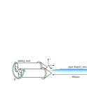
Madison et al. at Ecole Normale Supérieure (ENS) succeeded in observing a vortex and a vortex lattice in an atomic BEC (Madison 2000), using a method similar to the observation of superfluid helium in a rotating bucket (Yarmchuk 1979). A schematic illustration of their experimental setup is shown in Fig. 1. Since the magnetic trap is axially symmetric, its rotation cannot impart an angular momentum to the condensate. In this scheme, a laser beam is propagated along the -axis of the condensate. This beam rapidly oscillates around the -axis with a frequency much larger than the typical trapping frequency, which is effectively regarded to be as if two laser beams are located at an equilibrium position. Thus, the two laser beams break the axisymmetry of the condensate, allowing an angular-momentum transfer into the condensate. An optical spoon is then realized by rotating the two beams around the -axis. Since the beam width is larger than the radial size of the condensate, the condensate is trapped in a trap combining an axisymmetric harmonic potential and a nonaxisymmetric harmonic potential created by a stirring laser beam. In a rotating frame, the combined potential can be written as , where and are the coordinates in the rotating frame, is the anisotropic parameter, and . By rotating this potential at a frequency , a vortex is formed above a certain critical value of after the equilibration. When is increased further, multiple vortices appear, forming a triangular lattice. The quantized vortices can be directly visualized as “dips” in the transverse density profile of the TOF image.
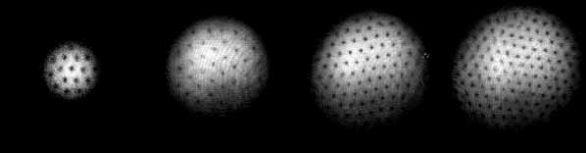
Following the experiments of the ENS group, other groups have also observed quantized vortices using slightly different methods under the concept of the rotating bucket. Abo-Shaeer et al. at Massachusetts Institute of Technology (MIT) observed a vortex lattice consisting of up to 100 vortices in a 23Na condensate, as shown in Fig. 2. 23Na condensates can be much larger than 87Rb condensates (Abo-Shaeer 2001). Hodby et al. created a vortex lattice by rotating the anisotropic magnetic trap directly without using a laser beam, which is similar to the rotating bucket experiment (Hodby 2002). This method has the advantage that a wider range of the anisotropic parameter can be selected than for the optical spoon. Rotating an optical spoon made by multiple-spot laser beams or narrow focusing beams has also used for nucleating vortices (Raman 2001).
In the above methods, the condensate was rotated by an external potential. Haljan et al. at Joint Institute for Laboratory Astrophysics (JILA), in contrast, created a vortex state by cooling an initially rotating thermal gas in a static confining potential (Haljan 2001). Thermal gas above the transition temperature was rotated by a slightly anisotropic trap. After recovering the anisotropy of the potential, the rotating thermal gas was evaporatively cooled until most of the atoms were condensed. Although the atom number decreased through the evaporative cooling, the condensate continued to rotate because the angular momentum per atom did not change and thus the vortex lattice was created. This method allows the investigation of the intrinsic mechanism of vortex nucleation, which is independent of the character of the stirring potential. In addition, since atoms can be selectively removed during the evaporation, spinning up of the condensate can be efficiently achieved by removing atoms extending in the axial direction, as opposed to the radial direction, and hence a BEC with a high rotation rate can be obtained.
3.2.2 Theory of vortex nucleation and lattice formation
(i) Surface mode instability
The critical rotation frequency indicates the energetic stability of the central vortex state and provides a lower bound for the critical frequency. Vortex nucleation of a non-rotating condensate occurs when the trap is rotated at a higher frequency than , to overcome the energy barrier that stops the transition from the nonvortex state to the vortex state (Isoshima 1999). The threshold of the rotation frequency for instability, leading to vortex nucleation, is related to the excitation of surface modes of the trapped condensate (Feder 1999b, Dalfovo 2000, Anglin 2001, Williams 2002, Simula 2002b). It has been shown that, according to the Landau criterion for rotationally invariant systems, the critical frequency is given by , where is the frequency of a surface mode with multipolarity . Above , negative-energy surface modes appear with high multipolarities in the spectrum of a non-rotating condensate (Isoshima 1999, Dalfovo 2000), which may lead to vortex generation. The negative-energy modes can grow only in the presence of dissipation, caused by e.g., thermal atoms (Williams 2002). This mechanism occurred in the experiment of the JILA group (Haljan 2001). In this experiment, vortices were formed by cooling a rotating thermal cloud to below , where the surface modes were excited by the “wind” of the rotating thermal cloud.
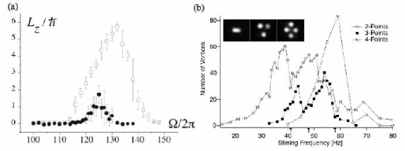
The nucleation frequency is insufficient to explain the results of the groups using external stirring potentials (Madison 2000, Abo-Shaeer 2001, Hodby 2002). For example, in the case of the ENS group, the number of nucleated vortices has a peak near , as shown in Fig. 3(a). These experiments confirm that instability occurs when a particular surface mode is resonantly excited by a deformed rotating potential. The optical spoon of the ENS group mainly excites the surface mode with (quadrupole mode). In a rotating frame with frequency , the frequency of the surface mode is increased by . This resonance thereby occurs close to the rotation frequency . In the TF limit, the dispersion relation for the surface mode is given by (Stringari 1996). Hence, it is expected that the quadrupole mode with is resonantly excited at . A theoretical study has revealed that, when the quadrupole mode is resonantly excited, an imaginary component appears in frequencies of fluctuations with high multipolarities (Sinha 2001). This indicates that dynamic instability can trigger vortex nucleation even at zero temperature. This scheme is supported further by the experiment of the MIT group (Raman 2001), where surface modes with higher multipolarities () were resonantly excited using multiple laser-beam spots, where the largest number of vortices were generated at frequencies close to the expected values , as seen in Fig. 3(b).
Another mechanism to produce vortex nucleation is formulated by considering elliptically-deformed stationary states of a BEC in a rotating elliptical trap. The stationary solutions can be obtained in the TF limit by solving the superfluid hydrodynamic equations (Recati 2001). At low rotation rates, only one stationary solution is found (“normal branch”). However, at higher rotation rates, specifically, a bifurcation of the solutions occurs and up to three stationary solutions appear, with two solutions in an “overcritical branch” and one normal-branch solution. Above of the bifurcation point, one or more of the solutions become dynamically unstable for fluctuations with high multipolarities (Sinha 2001), which leads to vortex formation (Parker 2006). Madison et al. followed these stationary states experimentally by adiabatically introducing trap ellipticity and rotation. They observed vortex nucleation in the expected dynamically unstable region (Madison 2001).
An overview on the problem of vortex nucleation in a trapped BEC can be seen in the review paper (Ghosh 2004).
(ii) Formation dynamics of a vortex lattice
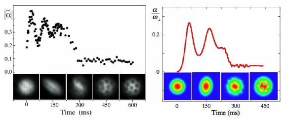
Madison et al. directly observed nonlinear processes such as vortex nucleation and lattice formation in a rotating condensate (Madison 2001). The left panel of Fig. 4 depicts the time development of the condensate ellipticity , where is the TF radius measured from the image. By suddenly turning on the rotation of the potential, the initially axisymmetric condensate undergoes a collective quadrupole oscillation in which the condensate deforms elliptically. This oscillation continues for a few hundred milliseconds with gradually decreasing amplitude. Then, the axial symmetry of the condensate suddenly recovers and concurrently the vortices enter the condensate from its surface, eventually settling into a lattice configuration.
This observation has been well reproduced by a simulation of the GP equation in 2D (Tsubota 2002, Kasamatsu 2003) and 3D (Kasamatsu 2005a) space. The results shown in the right panel of Fig. 4 were obtained by a 3D simulation with the parameters of the ENS group experiment. The simulation result shows that after a few hundred milliseconds, the boundary surface of the condensate becomes unstable and generates ripples that propagate along the surface, identified as invisible “ghost” vortices in the low-density surface region. The ripples develop into vortex cores, which enter the condensate. In these simulations, a dissipation term was introduced phenomenologically by rewriting the time derivative term of the GP equation (18) as , which caused the lattice configuration to settle. Other works have simulated vortex lattice formation using dissipation derived from the microscopic approach, such as quantum kinetic theory (Penckwitt 2002) or the classical field formalism (Lobo 2004). Long numerical propagation of the energy-conserving GP equation can cause crystallization of a lattice through the vortex–phonon interaction (Parker 2005)
(iii) Vortex nucleation by a moving object
Vortices can also be nucleated in BECs by a moving localized potential. Numerical simulations of the GP equation for a 2D uniform condensate flow around a circular hard-walled potential show that vortex–antivortex pairs nucleate when the flow velocity exceed a critical value (Frisch 1992). In trapped BECs, a similar situation can be realized experimentally using a narrow blue-detuned laser potential, being studied theoretically (Jackson 1998, Crescimanno 2000). In experiments by the MIT group, a repulsive laser beam was oscillated in an elongated condensate to study the dissipationless flow of a Bose gas (Raman 1999, Onofrio 2000). Although vortices were not observed directly, the measurement of condensate heating and drag above a critical velocity was consistent with the nucleation of vortices (Jackson 2000). Focused laser beams moving in a circular path around the trap center can also stir the condensate by nucleating vortices (Caradoc-Davies 1999, 2000, Lundh 2003). This scheme was used in the experiment detailed in Ref. (Raman 2001), where vortices were generated at lower stirring frequencies than the critical value given by surface mode instability.
3.3 Phase engineering
Atom optics techniques allow the controlled creation of vortices by imprinting a spatial phase pattern of the condensate wave function. Several ideas for the creation of vortices by this technique have been proposed theoretically, based on the coherent control of the time evolution of the wave function, instead of mechanical rotation (Marzlin 1997, 1998, Dum 1998, Williams 1999, Nakahara 2000, Andrelczyk 2001, Damski 2001, Nandi 2004, Kapale 2005, Möttönen 2003).
3.3.1 Phase-imprinting method
The first observation of a quantized vortex in an atomic-gas BEC was achieved in a two-component BEC consisting of 87Rb atoms with hyperfine spin states and (Matthews 1999a), which were confined simultaneously in almost identical magnetic potentials. Since the scattering lengths between atoms of and , and , and and are all different, the two states are not equivalent, and the two-component condensate is characterized by two-component order parameters.
In this experiment, condensed atoms are initially trapped in one state, say, the state. Then, a two-photon microwave field is applied, inducing coherent Rabi transitions of atomic populations between the state and the state. For a homogenous system in which both components have uniform phases, interconversion takes place at the same rate everywhere. However, the time variation of the spatially inhomogeneous potential changes the nature of the interconversion. This is a key point of the phase-imprinting method for vortex creation.
The underlying physics can be understood by considering a co-rotating frame with an off-centered perturbation potential at the rotation frequency . In this frame, the energy of a vortex with one unit of angular momentum is shifted by relative to its value in the laboratory frame. When this energy shift is compensated for by the sum of the detuning energy of an applied microwave field and the small chemical potential difference between the vortex and non-vortex states, a resonant transfer of population can occur. Experimentally, the rotating perturbation is created by a laser beam with a spatially inhomogeneous profile, rotating around the initial nonrotating component, say . By adjusting the detuning and , the component is resonantly transferred to a state with unit angular momentum by precisely controlling the time when the coupling drive is turned off (Williams 1999). This procedure results in a “composite” vortex, where the component has a vortex at the center, whereas the nonrotating component occupies the center and works as a pinning potential that stabilizes the vortex core (Kasamatsu 2005b).
As shown in Sec. 2.4, a far-off-resonant laser beam can create an external potential in the condensate. By directly applying a laser pulse with an inhomogeneous intensity to the condensate, the condensate phase can be modulated. This can be easily understood by observing the evolution of the phase by inserting the form into Eq. (3). When the laser intensity is much stronger than the other terms and the duration of the pulse is sufficiently short, the evolution of the phase is governed by . Since the potential amplitude of is proportional to the laser intensity, a suitable spatial variation of the intensity can imprint the phase into the condensate (Andrelczyk 2001). This phase-imprinting technique has been used to create a dark soliton (Burger 1999, Denschlag 2000), which is a topological excitation with a complete density dip across which the phase changes by . It is known that a dark soliton in a dimensional space larger than 2D experiences dynamical instability, called “snake instability”. This instability causes the decay of the dark solitons into a form of a vortex ring (Anderson 2001, Dutton 2001).
3.3.2 Topological vortex formation
Leanhardt et al. (Leanhardt 2002, 2003) used a method called “topological phase imprinting” (Nakahara 2000, Isoshima 2000, Ogawa 2002) to create a vortex in a trapped BEC. In this experiment, 23Na condensates were prepared in either a lower, , or upper, , hyperfine state and confined in a Ioffe–Pritchard magnetic trap, described by . A vortex was created by adiabatically inverting the axial bias field along the trap axis.
To interpret the mechanism, consider an alkali atom with a hyperfine-spin . The order parameter has three components and corresponding to , respectively. The basis vectors in this representation are . We introduce another set of basis vectors and , which are defined by . These vectors are related to the previous vectors as and . When the -axis is taken parallel to the uniform magnetic field, the order parameter of the weak field seeking state takes the form and , or in vectorial form as . When the magnetic field points in the direction , a rotational transformation with respect to the Euler angle gives , where and . The unit vector is the direction of the spin polarization. The three real vectors form a triad, analogous to the order parameter of the orbital part of superfluid 3He. The same amplitudes in the basis are , , and .
When the field is strong compared to the quadrupole field, the trapped condensate has an order parameter without vorticity. This configuration corresponds to and , where is the azimuthal angle. Then, is adiabatically decreased, where the adiabatic condition is required for atoms to remain in the weak field seeking state so that is always antiparallel to . In the final step, the external field is gradually increased in the opposite () direction. Then, the -vector points so that . Substituting these angles into and , we obtain and , which corresponds to a vortex with winding number . This result can be reinterpreted in terms of Berry’s phase (Ogawa 2002, Leanhardt 2002) (which is why it is called “topological phase imprinting”). When the hyperfine spin is in general, we obtain a vortex with a winding number since and have phases and , respectively (Shin 2004, Kumakura 2006).
When the bias field vanishes during the inversion (), a spin texture known as cross disgyration appears in the Ioffe–Pritchard trap. Here, the angle increases from to and and are identified with , where the -vector aligns with a hyperbolic distribution around the singularity at the center. This texture has a nonvanishing vorticity when . This spin texture has been observed as a coreless vortex composed of three-component order parameters of a spinor BEC (Leanhardt 2003).
3.3.3 Stimulated Raman process
Some papers proposed generating vortices in a BEC using stimulated Raman processes with configurations of optical fields that have orbital angular momentum (OAM) (Marzlin 1997, 1998, Dum 1998, Nandi 2004, Kapale 2005). A light beam with a phase singularity, such as a Laguerre-Gaussian (LG) beam, has a well-defined OAM along its propagation axis. The set of LG modes
| (19) |
defines a possible basis set to describe paraxial laser beams, where is the beam width, the winding number, and the number of radial nodes for radius . Each photon in the mode carries OAM along its direction of propagation.
A group at NIST (Anderson 2006, Ryu 2007) used a 2-photon stimulated Raman process with a Gaussian laser beam propagating along and a beam, carrying of OAM, propagating along . Interference of counter-propagating Gaussian beams generates a moving sinusoidal optical dipole potential, which can give a directed linear momentum (LM) to Bose-condensed atoms via Bragg diffraction. The potential generated by interference of the counter propagating and Gaussian beams is not sinusoidal but corkscrew-like, due to the radial intensity profile and the helical phase of the beam. Diffraction off this corkscrew potential produces a vortex state with a center-of-mass motion, where atoms that absorb a photon from one beam and simulatedly emit a photon into the other beam acquire both LM and OAM difference of the beams, which in this case was ( the photon wavevector) and , respectively.
They generated vortices of higher charge by transferring to each atom the angular momentum from several photons (Anderson 2006, Ryu 2007). This experiment directly demonstrated that the OAM of a photon is transferred coherently to an atom in quantized units of . In some situations it might be desirable to generate rotational states with no net LM. This could be accomplished by using an initial Bragg diffraction pulse to put atoms in a non-zero LM state from which they could subsequently be transferred to a rotational state with zero LM.
4 A single vortex in an atomic BEC
In this section, we concentrate on the problem of a single vortex state in a trapped BEC. As described in Sec. 3.1, vortex stability is ensured by the rotation of the system. Studying the motion of a vortex line is the first step towards understanding superfluid hydrodynamics in such a system. Trapped BECs are mesoscopic systems in the sense that the healing length is not significantly smaller than the sample size. Thus, vortex dynamics have noticeable effects on the collective excitation of the condensate, in contrast to the case for traditional superfluid helium systems.
4.1 Equilibrium properties
The solution of the GP equation shows that a vortex has a core with a size of the order of the healing length , in which the condensate density is zero. When , vortices are identified by a density dip in the transverse density distribution (in the plane). TOF observations by the ENS group (Madison 2000), however, show that the density is not completely zero in the dip. This result implies that the vortex line is not necessarily straight, because the condensate density along the -axis (rotation axis) is integrated for the transverse image. Surprisingly, such vortex bending remains stationary in the ground state of a cigar-shaped condensate (García-Ripoll 2001, Aftalion 2002, Modugno 2003, Aftalion 2003).
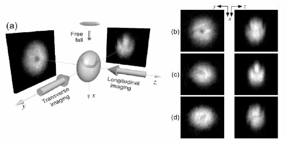
Evidence of vortex bending in the ground state was observed by the ENS group (Rosenbusch 2002). They prepared a single vortex state slightly above and equilibrated it for a sufficient long time. In the TOF measurements, two imaging beams were aligned along the and directions and probed the atom distribution simultaneously [Fig. 5 (a)]. The transverse image in Fig. 5 (b) shows the vortex line, corresponding to the lower atom density; it is not straight and has the shape of a wide “U”. Figure 5 (c) shows the decay of a U vortex for which the angular momentum has decreased significantly compared to Fig. 5 (b). In the longitudinal view, we can see a vortex off-center. In the transverse view, a narrow U can be seen.
This result is supported by theoretical analysis based on the 3D GP equation with experimentally appropriate parameters (García-Ripoll 2001, Aftalion 2002, Modugno 2003, Aftalion 2003), where the ground state with a rotation was calculated by minimizing the energy functional in Eq. (17). The central vortex is generally bent if the trap aspect ratio is much less than unity. A simple physical picture of the bending can be gained by viewing a cigar-shaped condensate as a series of 2D sheets at various (Modugno 2003). For each sheet, there is a corresponding 2D vortex stability problem with a critical frequency (see Sec. 3.1) above which a centered vortex is the stable solution. Since the effective 2D chemical potential is , the radius of the 2D condensate at becomes . Thus, is a decreasing function from to . For a given rotation frequency , the vortex line minimizing the total energy is well centered for and is strongly bent for , where . This bending is a symmetry-breaking effect, which does not depend on the presence of rotating anisotropy and which occurs even in a completely axisymmetric system (García-Ripoll 2001). A precursor of this bending effect can be found in the excitation spectrum of a condensate with a centered straight vortex (Svidzinsky 2000b, Feder 2001a), in which negative-energy modes localized at the core (so-called “anomalous modes”) appear with increasing . As these modes grow, the central vortex is pushed outward. This indicates that the bending instability needs a dissipation mechanism and that it takes a long time at low temperatures.
Figure 5 (d) shows a vortex line in the shape of an “S”, which can be regarded as a U vortex with a half part rotated by 180∘. An S single vortex can also be found by numerical simulation as the stationary state of an elongated condensate for a given rotation frequency (Aftalion 2003), having an energy higher than that of the U vortex (Komineas 2005).
4.2 Dynamical properties
4.2.1 Precession and decay of an off-centered vortex
Precession of a vortex core off-center in a condensate is a simple example of vortex motion. Core precession can be described in terms of a Magnus force effect. A net force on a quantized vortex core creates a pressure imbalance, resulting in core motion perpendicular to both the force and the vortex quantization axis. In the case of trapped BECs, these net forces can be caused by either condensate density gradients (Svidzinsky 2000a, b, Jackson 1999, McGee 2001) or drag due to thermal atoms (Fedichev 1999). The former may be thought of as a sort of effective buoyancy. Typically, the total buoyancy force is towards the condensate surface and the net effect is a precession of the core around the condensate axis via the Magnus effect. The latter causes radial drag and spiraling of the core towards the condensate surface due to energy dissipation and damping processes.
Core precession has been investigated in detail by the JILA group (Anderson 2000). Starting with a composite vortex created by the phase-engineering method of Sec. 3.3, they selectively removed components filling the vortex core with resonant light pressure. In the limit of complete removal, a single-component vortex state with a bare core can be obtained. The vortex was off-center because of the instability of the formation process. The precession frequency was determined from the vortex position taken directly from the density profile. The vortex core precessed in the same direction as the vortex fluid flow around the core. The obtained result of 1.8 Hz agrees well with analytical results based on the Magnus force picture (Svidzinsky 2000a, b) and more precise numerical simulations (Jackson 1999, McGee 2001, Feder 2001a).
In some results, the vortex core disappeared from the observed images during the time evolution. However, these were not associated with the decay of vortices because there was no evidence of radial spiral motion due to energy dissipation, which could be caused by the thermal drag (Fedichev 1999) or the sound radiation from a moving vortex (Lundh 2000, Parker 2004). Subsequently, an experiment using the surface-wave spectroscopic technique revealed that vortices were actually present for a long time in the condensate (Haljan 2001). The main cause of the disappearance was the tilting motion of a vortex, the lowest odd-order normal mode of a single-vortex state, which is sensitive to small trap anisotropy (Svidzinsky 2000b).
4.2.2 Vortex dynamics coupled with collective modes
Vortex dynamics are greatly affected by the overall collective motion of the condensate because of the mesoscopic nature of the system. Here, we detail several interesting results of coupled dynamics. The determination of the frequency of the collective modes allows precise measurement of the angular momentum carried by the quantized vortices.
(i) Transverse quadrupole mode
The collective modes of a trapped condensate can be classified by expressing the density fluctuations in terms of polynomials of degree in the Cartesian coordinates . The quadrupole modes are characterized by a density fluctuation with a polynomial of second order, e.g., , which gives six normal modes. In an axisymmetric harmonic potential, linear combinations of the diagonal components , , and describe three normal modes: one transverse mode with and two radial-breathing modes with , where is the projected angular momentum on the symmetry axis. The remaining three normal modes are associated with the off-diagonal components , , and , which are scissors modes (Guèry-Odelin 1999, Marago 2000).
The first study was done for the excitation of two transverse quadrupole modes with (Chevy 2000). When a vortex is present in a condensate, the frequencies of the quadrupole modes increase by because of broken rotational symmetry (Zambelli 1998), where stands for the average within the condensate. The increase causes precession of the eigenaxes of the quadrupole mode at an angular frequency . By measuring the angular velocity of this precession, we can determine the mean angular momentum of the condensate. This spectroscopic method has also been used to characterize the tilting motion of a vortex (Haljan 2001) and the winding number of a single vortex (Leanhardt 2002).
Excitation of the transverse quadrupole mode yields further interesting vortex dynamics. The ENS group observed that when the superposition of the quadrupole modes are excited with equal amplitudes, the oscillation of the mode decays faster than that of the mode (Bretin 2003). A possible physical origin of this phenomenon is that the mode decays to Kelvin modes through a non-linear Beliaev process. This is supported by theoretical analysis based on the BdG equation (Mizushima 2003). Kelvin modes correspond to long-wavelength helical traveling waves along a vortex line with a dispersion relation . According to the Kelvin–Helmoltz theorem, the Kelvin modes rotate always in the sense opposite to the vortex velocity field. Consequently, the angular momentum of a quantum of a Kelvin mode associated with a singly-quantized vortex is . Because of the negative angular momentum with respect to the vortex winding number, this mechanism is effective only for the mode. From the energy and angular momentum conservation, an excitation of the quadrupole mode can decay to a pair of Kelvin waves with wave vectors and , while angular momentum conservation forbids the decay of the mode.
(ii) Gyroscope motion
What happens when the other quadrupole modes are excited in a condensate with a vortex? The Oxford group studied the response of a condensate with a vortex when the or scissors modes are excited (Hodby 2003). Similar to the case of transverse quadruople modes, in the presence of the vortex, the plane of oscillation of a scissors mode precesses slowly around the axis. In polar coordinates, the scissors oscillation is in the direction and the precession is in the direction, as shown schematically in Fig. 6. This can be regarded as a kind of gyroscope motion of the vortex line (Stringari 2001).
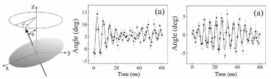
The relationship between the precession rate and can be derived by considering the scissors mode as an equal superposition of two counter-rotating modes. These modes represent a condensate tilted by a small angle from the horizontal plane rotating around the axis at the frequency of the scissors oscillation, = . The symmetry and degeneracy of these modes are also broken by the axial angular momentum . By applying a similar argument as that for transverse quadrupole modes (Stringari 2001), the precession rate is related to the frequency splitting, , allowing the angular momentum to be determined.
The precession associated with gyroscope motion can be seen in the results of Fig. 6(a) and (b), corresponding to a slowly varying oscillation component. The pattern of increase and decrease of the amplitude is exchanged between (a) and (b), with different directions of the excitation. This is clear evidence of a slow precession along the -direction. The results also show that the motion of the vortex core exactly follows the axis of the condensate. These observations can be well reproduced by direct numerical simulations of the 3D GP equation (Nilsen 2003). From the precession rate, the measured angular momentum per particle associated with a vortex line was found to be .
4.2.3 Splitting of a multiply quantized vortex
The energy cost to create a vortex is less favorable than single-quantized vortices, as seen in Eq. (16). This raises an interesting question as to what happens when such an unstable vortex is created. As it happens, topological phase imprinting, shown in Sec. 3.3.2, can be used to create an unstable vortex.
The stability characteristics of a multiply quantized vortex in a trapped BEC exhibit an interesting interaction dependence because of the finite size effect (Pu 1999). BdG analysis for a cylindrical system reveals complex eigenvalue modes, which implies that a multiply quantized vortex is dynamically unstable. For a vortex with a winding number , angular momentum conservation leads to constraints on the normal mode functions and , where denotes the angular momentum quantum number of the mode. For there are alternating stable and unstable regions with respect to the interaction parameter ; the first and second regions appears for and . Numerical simulations demonstrate that when a system is in an unstable region, a doubly quantized vortex decays into two singly quantized vortices (Möttönen 2003).
An experiment by the MIT group studied the splitting process of a doubly quantized vortex and its characteristic time scale as a function of (Shin 2004). The results show that a doubly quantized vortex decays, but that the lifetime increases monotonically with , showing no periodic behavior. This contrary to the above theoretical prediction. Recent numerical studies of 3D GP equations reveal this mysterious observation, emphasizing that the detailed dynamical behavior of a vortex along the entire -axis is relevant for characterizing the splitting process in an elongated condensate (Huhtamäki 2006a, Muñoz Mateo 2006).
The trigger for splitting instability is likely to be gravitational sag during the formation process with a reversing axial bias field (Huhtamäki 2006a). In experiments, absorption images were restricted to a 30-m thick central slice of the condensate to increase the visibility of the vortex cores. The experimental results in Fig. 7(a) shows that the fastest decay occurs at , consistent with the BdG and numerical analysis. As the particle number increases, the first instability region () moves progressively away from the central slice toward the edges of the condensate because of the trapping potential. As a consequence, the splitting instability of the vortex core has to propagate from those regions to the center. This process is responsible for the monotonic increase in the lifetime for . According to the theory, a second minimum is expected about . Even though no such minimum occurs, a change in the slope of the predicted curve at is seen as enters the second instability region (Huhtamäki 2006a, Muñoz Mateo 2006). Figures 7 (b)–(e) show the time evolution of the splitting process for . The first and second instability regions correspond to the shaded zones in Fig. 7 (b). This clearly shows that at ms, the splitting process has already begun in both the edges and the center of the condensate. The different precession frequency along different slices causes inter-winding of two single-quantized vortices. However, the two vortex cores near the central slice still overlap (Fig. 7 (c)) and thus cannot be experimentally resolved until much longer times. At ms (Fig. 7 (d)), the vortex cores begin to disentangle so that they can be unambiguously resolved at ms (Fig. 7(e)). Thus, there is no contradiction with the theoretical prediction.
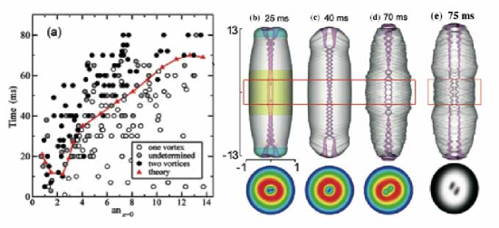
The physical origin of the periodic appearance of the unstable region is anomalous modes with negative eigenvalues. When the eigenvalue of positive-energy modes coincides with the absolute value of the eigenvalue of negative-energy modes, a complex eigenvalue mode are produced through mutual annihilation of these two excitations (Skryabin 2000, Kawaguchi 2004, Jackson 2005, Lundh 2006); the total angular momentum of these excitations is also vanished. Since the dependence of the negative-energy eigenvalues is very different from that of positive-energy ones, the above matching condition can be satisfied in sequence with increasing , which results in the periodic appearance of the complex-eigenvalue modes. Thus, splitting instability of a multiply quantized vortex can be suppressed for a particular trap asymmetry and interaction strength because the collective excitations depend strongly on the character of the trapping potential (Huhtamäki 2006b). It has also been predicted that multiply quantized vortices can be stabilized by introducing a suitable localized pinning potential (Simula 2002a) or non-simply connected geometry such as quartic confinement (Lundh 2002). Very recently, splitting dynamics of a quadruply quantized () vortex was reported (Isoshima 2007).
5 A lattice of quantized vortices in an atomic BEC
We now address the issue of a rapidly rotating BEC where many vortices have been nucleated and arranged into a regular triangular lattice (Abo-Shaeer 2001, Coddington 2004). We first present a discussion of the equilibrium properties of a rapidly rotating condensate, and then present the basic theoretical background for its description. The equilibrium properties of vortex lattices in a trapped BEC have been extensively studied by the JILA group (Schweikhard 2004a, Coddington 2004). We next discuss the collective dynamics of an assembly of vortices in a trapped BEC. Finally, we discuss an unconventional vortex phase which occurs in the presence of an externally applied potential created by laser beams.
5.1 Equilibrium properties
For very large , the rotation of the superfluid mimics a rigid body rotation with by forming a vortex lattice. Using the fact that the vorticity is given by the form , we find that the average vorticity per unit area is given by , where is the number of vortices per unit area. Hence, the density of the vortices is related to the rotation frequency as (Feynman 1955). This relation can be used to estimate the maximum possible number of vortices in a given area as a function of . As shown below, the properties of a vortex lattice can be characterized by the nearest-neighbor lattice spacing , defined by the area per vortex , and by the radius of each vortex core .
Note that the GP energy functional of Eq. (17) in a rotating frame can be rewritten as
| (20) |
where is the effective trapping potential combined with the centrifugal potential; the rotation effectively softens the radial potential and vanishes at . Because the first term in Eq. (20) reads , it can be neglected in the TF limit and the rigid-body rotation limit . Then, the TF radius is given by with for nonrotating condensate and an aspect ratio of . Thus, measuring will give the rotation rate of the condensate (Raman 2001, Haljan 2001). Also, in the high rotation limit , the condensate flattens out and reaches an interesting quasi-2D regime; current experiments have reached (Coddington 2004).
Abrikosov triangular lattice of quantized vortices have been observed experimentally, as shown in Fig. 2. Direct imaging allows a detailed investigation of the nature of a vortex lattice in an inhomogeneous superfluid. Here, we summarize the salient results and theoretical interpretations of these observations.
5.1.1 Lattice inhomogeneity
Experimental observations (Abo-Shaeer 2001, Engels 2002) and numerical simulation of the 3D GP equation (Feder 2001b) have revealed that for a finite-size trapped BEC, the vortex density in a lattice is lower than the rigid-body estimate and the lattice is remarkably regular. Sheehy and Radzihovsky explained these points analytically in the TF limit (Sheehy 2004a, b); they derived a small, radial-position-dependent, inhomogeneity-induced correction term to the vortex density as
| (21) |
This result indicates that the vortex density is always lower than the rigid-body estimate of the first term in Eq. (21). Also, the vortex density is higher in regions where the condensate density is most uniform, that is, the central part of a harmonically trapped gas. However, the position-dependent correction is small ( changes less than a few % over a region in which the atom density varies by 35%), which seemingly causes regularity of the lattice. These results have been confirmed by a detailed experimental study (Coddington 2004). It should be also noted that inhomogeneity in the area density of vortices can also be derived in the limit of the lowest Landau level (Watanabe 2004, Cooper 2004, Aftalion 2005, Baym 2007), as explained below.
5.1.2 Attainment of the lowest Landau level regime
Note that the first term in Eq. (20) can be identified as the Hamiltonian of a charge particle moving in the plane under a magnetic field with a vector potential . If the interaction is neglected (), the eigenvalues of the Hamiltonian of Eq. (20) forms Landau levels as , where is the Landau level index and labels the degenerate states within a Landau level. The lowest energy states of two adjacent Landau levels are separated by , whereas the distance between two adjacent states in a given Landau level is ; when , all states in a given Landau level are degenerate. Physically, this corresponds to the case where the centrifugal force exactly balances the trapping force in the - plane, and only the Coriolis force remains. The system is then invariant under translation and hence has macroscopic degeneracy. This formal analogy has led to the prediction that quantum Hall-like properties would emerge in rapidly rotating BECs (Ho 2001, Viefers 2000, Cooper 2001, Sinova 2002, Regnault 2003, 2004, Cazalilla 2005, Chang 2005, Rezayi 2005, Morris 2006).
Interaction effects mix different (, ) states. Because the density of the system drops as , the interaction energy can become small compared with the Landau level separation . In this limit, particles should condense into the lowest Landau level (LLL) with . Then, the system enters the “mean field” quantum Hall regime, where the wave function can be described by only the LLL orbitals with the form , where , is the positions of vortices (zeros), and is a normalization constant. The minimization of Eq. (20) using the ansatz is a useful theoretical prescription to tackle the properties of rapidly rotating BECs (Watanabe 2004, Cooper 2004, Aftalion 2005, Sonin 2005b, Aftalion 2006, Cozzini 2006).
Schwaikhard et al. created rapidly rotating BECs by spinning condensates to (Schweikhard 2004a). When the condensate enters the LLL regime, characteristic equilibrium properties appear, as described below.
(i) Global structure
In the LLL limit, the radial condensate density profile with uniform vortex distribution has been predicted to change from a parabolic TF profile to a Gaussian profile as is increased (Ho 2001). However, no signs of such crossover have been found in experiments; even when the dynamics were restricted to the LLL, the density profile remained a parabolic TF profile as (Schweikhard 2004a, Coddington 2004). This result can be seen qualitatively from the energy minimization under the LLL limit with nonuniform vortex density (Watanabe 2004, Cooper 2004, Aftalion 2005). As long as the total number of vortices is much larger than unity (), the energy in the LLL regime is given by
| (22) |
plus terms involving the trapping potential in the -direction. Here, is the coarse-grain averaged density profile in order to smooth the rapid variations at the vortex cores. Then, the interaction parameter is renormalized to , where is the Abrikosov parameter. The energy (22) is then minimized by the TF profile, .
Since the energy (22) depends only on the smoothed density, the vortices adjust their locations so that the smoothed density becomes an inverted parabola. In the LLL regime, the relation between the condensate density and the mean vortex density, is given by (Ho 2001, Aftalion 2005). If the density profile is Gaussian, the vortex density is constant. However, for a TF profile,
| (23) |
This result is similar to Eq. (21) in the low rotation regime, where the coefficient of the second term is different. Since the second term is smaller than the first, as , the density of the vortex lattice is basically uniform, consistent with the argument in Sec. 5.1.1. Turning the argument around, very small distortions of the vortex lattice from perfect triangular can result in large changes in the global density distribution such that the TF form is energetically favored rather than the Gaussian.
(ii) Vortex core structure and fractional area
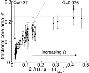
Another interesting characteristic of the LLL is that the vortex core is of the same size as the distance between adjacent vortices. The radius of a single vortex core is of order , so that a vortex core would begin to overlap the next at . This gives an upper-critical rotation frequency rad/sec, which is an experimentally accessible rate. However, there is no phase transition associated with vortex cores overlapping in a rotating condensate. Rather, vortex cores begin to shrink as the intervortex spacing becomes comparable to the healing length , and eventually the core radius scales with the intervortex spacing (Fischer 2003, Baym 2004b, Watanabe 2006).
Figure 8 shows the measured fractional area, defined as , as a function of the inverse of the LLL parameter (Schweikhard 2004a, Coddington 2004). The linear rise of at small occurs because the core size remains constant, while increases linearly with . Explicitly, the core radius was estimated numerically as (Schweikhard 2004a), and by neglecting the effect of inhomogeneity. These values yield , shown by the dashed line in Fig. 8, where and were used for the estimation. The flattening of with increasing is a consequence of the vortex radius scaling with the intervortex spacing. The upper dotted line shows the upper limit , obtained by using the oscillator -state structure as the profile of a vortex core in the LLL limit, where is regarded as the radius of the (cylindrical) Wigner–Seitz cell around a given vortex. The data in Fig. 8 show the expected initial linear rise, with the predicted scaling of the core radius with intervortex spacing. More detailed theoretical studies which treat the core structure explicitly obtain excellent agreement with the experimental results (Cozzini 2006, Watanabe 2006).
5.2 Collective dynamics of a vortex lattice
5.2.1 Vortex lattice dynamics coupled with collective modes
As shown in Sec. 4.2.2, vortex states undergo interesting responses to excitation of the transverse quadrupole modes with . Similar studies have been made for rapidly rotating BECs. In this case, the dispersion relation of the quadrupole modes is given by (Cozzini 2003), which has been measured experimentally (Haljan 2001). When , we have and , reflecting the tendency of the system to become unstable against quadrupole deformation. Excitation of the quadrupole mode for induces large deformations of the condensate and nonequilibruim dynamics of vortex lattices (Engels 2002). Interestingly, when the mode was excited, a vortex lattice was distorted to form a one-dimensional set of closely spaced vortices. This observation was explained by the fact that vortices should follow the stream line of the background quadrupole velocity field (Cozzini 2003, Mueller 2003). In contrast, excitation of an mode dissolved the regular lattice, where the vortex lines were randomly arranged in the - plane but were still strictly parallel along the -axis.
As stated in Sec. 5.1, a centrifugal force distorts the cloud into an extremely oblate shape, and thus the rotating cloud approaches the quasi-2D regime. Excitation of an axial breathing mode () has been used to confirm the 2D signature of a rapidly rotating BEC (Schweikhard 2004a). For a BEC in the axial TF regime, an axial breathing frequency has been predicted in the limit (Cozzini 2003), whereas is expected for a noninteracting gas, expected for . Schweikhard et al. observed a crossover of from to with increasing (). Also, excitation of the scissors mode in a condensate with a vortex lattice induces a collective tilting mode of the vortex array (the lowest-energy Kelvin wave of the lattice) (Smith 2004), referred to as an anomalous scissors mode (Chevy 2003).
5.2.2 Transverse oscillation of a vortex lattice: Tkachenko mode
The dynamics of vortex lattices itself raises many interesting problems. It should be possible to propagate collective waves in a transverse direction to the vortex lattice in the superfluid, called Tkachenko (TK) modes. For an incompressible superfluid, the dispersion law is given by . The TK modes of a vortex lattice in a trapped BEC have been analyzed theoretically (Baym 2003, Mizushima 2004, Baksmaty 2004, Baym 2004a, Cozzini 2004, Gifford 2004, Sonin 2005a, b) and observed experimentally (Coddington 2003).
Experimentally, TK modes have been excited by the selective removal of atoms at the center of a condensate with a resonant focused laser beam, or by the insertion of a red-detuned optical potential at the center to draw atoms into the middle of the condensate. The former method has also been used to create long-lived vortex aggregates (Engels 2003). In the experiment, the TK modes were identified by the sinusoidal displacement of the vortex cores with the origin at the center of the condensate; see Fig. 9(A). TK modes can be classified by the quantum number , associated with radial and angular nodes, in a presumed quasi-2D geometry.
To explain the observed frequency of the TK mode , the effects of compressibility should be taken into account. According to the elastohydrodynamic approach developed by Baym (Baym 2003), the TK frequency is described by the compressional modulus and shear modulus of the vortex lattice, included in the elastic energy
| (24) |
where is the continuum displacement field of the vortices from their home positions. In the incompressible TF regime, . Then, the upper branch of the energy spectrum follows the dispersion law with sound velocity , being the standard inertial mode of a rotating fluid and having a gap at . Conversely, the low frequency branch corresponds to the TK mode and has
| (25) |
For large , this reproduces the original TK frequency , while for small it exhibits the quadratic behavior . The transition between and dependence occurs at . This suggests that the effects of compressibility, characterizing the dependence, play a crucial role in the TK mode. Thus, this regime is distinguished from the usual incompressible TF regime as the “soft” TF regime. When the finite compressibility is included, the observed values of are well explained (Baym 2003, Cozzini 2004, Sonin 2005a). First-principle simulations based on the GP formalism also agree excellently with the experimental data (Mizushima 2004, Baksmaty 2004).
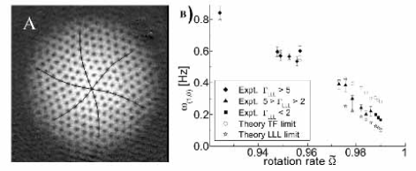
In the LLL limit, corrections to the elastic shear modulus of the vortex lattice are important; with increasing , its value eventually reaches (Baym 2003). Using this value, Schweikhard et al. compared the measured with the theoretical prediction, finding a crossover of from the TF results to the LLL results, as shown in Fig. 9(B). However, more detailed theoretical analysis in the LLL limit revealed that the value of the shear modulus is estimated as , which is a factor of 10 larger than (Sinova 2002, Sonin 2005b, Cozzini 2006). This indicates that even though the equilibrium properties in the experiment are consistent with the LLL picture, the data of the TK frequency are still far from the LLL limit. One possible explanation of this discrepancy is an underestimate of the rotation rate from the aspect ratio of the cloud due to the defocus of the imaging camera or the breakdown of the TF theory (Watanabe 2007).
5.3 Vortices in an anharmonic potential
For a rotating condensate with a frequency in a harmonic potential , the centrifugal potential cancels the confinement, thus preventing a BEC from rotating at beyond . This restriction can be avoided by introducing an additional quartic potential, so that the combined trapping potential in the plane becomes , where the dimensionless parameter characterizes the relative strength of the quartic potential. The properties of a rotating condensate in an anharmonic potential have recently attracted a lot of theoretical attention (Fetter 2001b, Lundh 2002, Fischer 2003, Kasamatsu 2002a, Kavoulakis 2003, Aftalion 2004, Jackson 2004a, b, Fetter 2005, Danaila 2005, Kim 2005, Bargi 2006, Fu 2006).
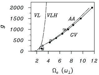
The vortex phases in an anharmonic trap are quite different from those in a harmonic trap, since it is possible to rotate the system arbitrarily fast. The predicted phase diagram of the vortex states as a function of interparticle interaction strength versus rotation rate is shown in Fig. 10. For small , the equilibrium state is the usual vortex lattice state. As increases, the vortices begin to merge in the central region and the centrifugal force pushes the particles towards the edge of the trap. This results in a new vortex state consisting of a uniform lattice (multiple circular arrays of vortices) with a central density hole. The central hole becomes larger with increasing , and the condensate forms an annular structure with a single circular array of vortices. A further increase of stabilizes a giant vortex, where all vortices are concentrated in the single hole (Fischer 2003).
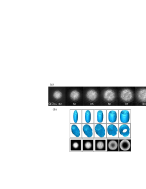
A combined harmonic-plus-quartic potential was formulated by the ENS group by superimposing a blue detuned laser with the Gaussian profile (Bretin 2003). Since the waist of the beam propagating along the -axis is larger than the condensate radius, the potential created by the laser can be written as . The second term leads to a reduction of the transverse trapping frequency and the third term provides the desired quartic confinement, giving Hz and for . Figure 11 shows experimental images of the condensate density as the rotation frequency is increased (Bretin 2003). For , the vortex lattice is clearly visible. When , however, the vortices becomes gradually difficult to observe and the images become less clear for ( Hz), which suggests a transition into a new vortex phase.
Despite the visibility of the cores, the angular momentum of the condensate monotonically increased, confirmed by the measurement of and surface wave spectroscopy. Hence, the most plausible explanation for this mysterious observation is that the vortex lines are still present, but strongly bent when . This bending may occur due to the finite temperature effect on the fragile vortex lattice at a high rotation rate; numerical simulations of the 3D GP equation show that, when looking for the ground state of the system using imaginary time evolution of the GP equation, much longer imaginary times were required to reach a well ordered vortex lattice for than for . Compared with the numerical results shown in the bottom in Fig. 11, the condensate should still have an ordered visible lattice even for . To observe the density hole at the center, it is necessary to rotate at a slightly faster rate than the upper frequency used in this experiment.
5.4 Vortex pinning in an optical lattice
Rotating BECs combined with an optical lattice are an interesting system, which has two competing length scales, vortex separation and the periodicity of the optical lattice. The structure of the vortex lattice is strongly dependent on the externally applied optical lattice. Various vortex phases appear depending on the number of vortices per pinning center, i.e., the filling factor. The JILA group formulated a rotating optical lattice using a rotating mask (Tung 2006). Such a rotating optical lattice provides a periodic pinning potential which is static in the corresponding rotating frame. The authors have observed a structural crossover from a triangular to a square lattice by increasing the potential amplitude of the optical lattice, as shown in Fig. 12. These observations are consistent with theoretical studies (Reijnders 2004, Pu 2005). The rotating optical lattice provides new phenomena in vortex physics for rotating bosons; such as the realization of a driven vortex system in a periodic array (Kasamatsu 2006) or strongly correlated phases in rotating bosons (Bhat 2006).
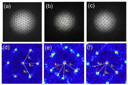
6 Other topics and future studies
In this section, we discuss other intriguing problems associated with quantized vortices in atomic BECs. Since many theoretical works have predicted novel properties of vortices under a variety of situations, it is impossible to refer to all studies in this section. We thus select some important issues that have been highlighted in the ultracold atom community or are likely to be investigated in experiments in the near future.
6.1 A vortex in an attractively interacting BEC
Although we have dealt primarily with vortices in repulsively interacting BECs, vortices in attractively interacting BECs characterized by a negative s-wave scattering length have also received theoretical interest. A homogenous BEC with is never stable due to self-focusing collapse, but a BEC in a confining potential can remain stable as long as the number of condensed atoms lies below a critical value (Bradley 1995). This is because the self-focusing can be balanced by the kinetic energy (quantum pressure), which tends to defocus the wave function.
Since a central vortex state reduces the peak density, it may help stabilization of a trapped condensate with in the sense that it can contain a larger number of atoms by suppressing self-focusing. However, for excitation of a vortex in a harmonically trapped BEC with is prohibited by the center-of-mass motion, which is the lowest energy state for a given angular momentum (Wilkin 1998). Some authors have proposed that the use of an anharmonic confinement can support a stable vortex phase as well as regimes of center-of-mass motion (Lundh 2004, Kavoulakis 2004, Ghosh 2004b, Collin 2005). The vortex state in this system can be regarded as a ring bright soliton with nonzero winding number (Carr 2006), showing interesting splitting dynamics dominated by the dynamical instability of the quadrupole mode (Saito 2002).
6.2 Vortices in dipolar condensates
BECs of chromium atoms have recently been created (Griesmaier 2005), exhibiting a larger magnetic-dipole moment (; is the Bohr magneton) than those of typical alkali atoms (). This opens the door for studying the effect of anisotropic long-range interactions in BECs. The interaction potential between two magnetic dipoles separated by is given by , where is the vacuum magnetic permeability and . Such dipole–dipole interactions contribute to the GP equation as a nonlocal mean-field potential as . Since the scattering length can be tuned to zero by a Feshbach resonance technique, we can obtain novel quantum ferrofluids dominated by the dipole–dipole interaction (Lahaye 2007).
The principal effect of on the equilibrium properties of a condensate is to cause distortion of its aspect ratio so that it is elongated along the direction of the dipoles. This feature affects the stability of a vortex in a dipolar BEC; the thermodynamic critical rotation frequency decreases for a condensate in a pancake-shaped trap (), while it increases a cigar-shaped trap (), compared to that of a conventional BEC (Sec. 3.1) (O’Dell 2007). Interestingly, the critical frequency can become larger than the onset of the dynamical instability of a rotating condensate (see Sec. 3.2.2). This is an intriguing regime where a rotating dipolar BEC is dynamically unstable but vortices will not enter (Bijnen 2007). Numerical simulations show that the structure of vortices has a craterlike shape for and has an elliptical shape for (Pu 1999). Rapidly rotating dipolar BECs possess a rich variety of vortex phases characterized by different symmetries of the lattice structure (Cooper 2005, Zhang 2005, Komineas 2007).
6.3 Melting state of vortex lattices: beyond the LLL regime
At sufficiently high rotation rates, a vortex lattice should melt via quantum fluctuations (Sinova 2002) and the system should then begin to enter a strongly-correlated vortex liquid phase. Exact diagonalization studies for small number of bosons have revealed that the ground states exhibit strong analogy with the physics of electronic fractional quantum Hall states (Viefers 2000, Cooper 2001, Paredes 2002, Regnault 2003, 2004, Ghosh 2004a); for specific filling factors , i.e., the ratio of the total number and the vortex number, the ground state possesses incompressibility characterized by the energy gap. For example, at angular momentum , where , the exact ground state is an -particle fully symmetric Laughlin wave function adopted for bosons: with .
The conditions for the formation of these states have been expressed as . It can be seen that an unrealistically high rotation is necessary to satisfy the condition; observed filling factors are always greater than 100 (Schweikhard 2004a), which are still deeply within the mean-field GP regime. To overcome this difficulty, insertion of a 1D optical lattice along the -direction has been proposed to enhance the quantum fluctuations of the vortices (Martikainen 2003, Snoek 2006). Then, the optical lattice divides the condensate into pancake fractions coupled by a tunneling process between near neighbors and in a single pancake is greatly reduced. Achieving this regime experimentally remains an important challenge.
6.4 Spontaneous vortex generation associated with phase transitions
In 2D systems with continuous symmetry, true long-range order is destroyed by thermal fluctuations at any finite temperature. For 2D Bose systems, a quasi-condensate can be formed with a correlation decaying algebraically in space, where superfluidity is still expected below a certain critical temperature. This 2D phase transition is closely connected with the emergence of thermally activated vortex–antivortex pairs, known as the Berezinskii–Kosterlitz–Thouless (BKT) phase transition occurring at (Berezinskii 1972, Kosterlitz 1973). For , isolated free vortices are absent; vortices always exist only in the form of bound pairs, formed by two vortices with opposite circulations. The contribution of these vortex pairs to the decay of the correlation is negligible, and the algebraic decay is dominated by phonons. For , the free vortices form a disordered gas of phase defects and give rise to an exponential decay of the correlation.
Recently, the BKT transition was observed experimentally in ultracold atomic gases (Hadzibabic 2006, Schweikhard 2007, Krüger 2007, Hadzibabic 2007). In the ENS experiment, a 1D optical lattice was applied to an elongated condensate, splitting the 3D condensate into an array of independent quasi-2D BECs (Hadzibabic 2006). The interference technique revealed the temperature dependence of an exponent of the first-order correlation function of the fluctuating 2D bosonic field (Polkovnikov 2006). A universal jump in the superfluid density characteristic of the BKT transition was identified by observing the sudden change of the exponent, where the finite size effect causes a finite-width crossover rather than a sharp transition. Surprisingly, the microscopic origin of this transition, i.e., whether or not it is a BKT type transition, was directly clarified from the image of the interference of the two 2D condensates. If isolated free vortices are present in either of two condensates, the interference fringes exhibit dislocations. Such a dislocation has been observed in the high- region of the crossover, supported by the theory using classical field simulations (Simula 2006).
In contrast, the JILA group inserted a 2D optical lattice into a condensate to create 2D bosonic Josephson junction arrays (Schweikhard 2007). Each condensate was localized at a site . Each had an individual phase and was separated by a potential barrier from the nearest neighbors. This system can be mapped to the XY model, , where denotes the tunneling coupling and the sum is restricted within nearest neighbors (Trombettoni 2005). The XY model is expected to exhibit a BKT transition at from free-energy considerations. Direct imaging of vortex cores and the systematic determination of revealed evidence for a gradual increase in the number of isolated free vortices at , consistent with the BKT crossover picture.
A related work is vortex formation by merging three uncorrelated BECs that are initially separated by a triple well potential (Scherer 2007). Depending on the relative phases between the condensates and merging rate, vortices formed stochastically without applying rotation. This situation is useful to clarify the mechanism of spontaneous vortex generation through the Kibble-Zurek mechanism (Kibble 1976, Zurek 1985) during rapid phase transition (Leggett 1998, Kasamatsu 2002b).
6.5 Skyrmions in multi-component BECs
Another important issue in vortex physics is to elucidate the vortex phases in multicomponent (spinor) BECs. Multicomponent order parameters allow the formation of various unconventional topological defects with complex properties that arise from interactions between different order parameter components. Since it is possible to load and cool atoms in more than one hyperfine spin state or more than one atomic element in the same trap, multicomponent condensates can be realized experimentally. Such systems offer an ideal testing ground for the study of unconventional topological defects; similar structures appear in other condensed matter systems such as superfluid 3He and unconventional superconductors, and theories in high-energy physics and cosmology. A few experimental works have investigated the properties of composite vortices in spinor BECs (Leanhardt 2003, Schweikhard 2004b, Sadler 2006). A review of this topic is presented in Ref. (Kasamatsu 2005b) and references therein.
6.6 Vortices in Fermion condensates
Quantum degenerate Fermi gases provide a remarkable opportunity to study strongly interacting fermions. In contrast to other Fermi systems, such as superconductors, neutron stars, or the quark–gluon plasma, these gases have low densities and their interactions can be precisely controlled over a wide range by using a Feshbach resonance technique. For small and negative values of the scattering length the equation of state approaches the limit of a noninteracting Fermion gas, while for small and positive values the system behaves as bosons of tightly-bound molecules. Therefore, we can study the crossover from a BEC of molecules to a Bardeen–Cooper–Schrieffer (BCS) superfluid of loosely-bound Cooper pairs when an external magnetic field is varied across a Feshbach resonance. Recent topics in this rapidly growing field are presented in the comprehensive review paper Ref. (Giorgini 2007).
Decisive evidence for fermion superfluidity was obtained from observations of long-lived vortex lattices in a strongly-interacting rotating Fermion gas (Zwierlein 2005). Rotation was applied to an ultracold gas of 6Li atoms in , in a similar way as for conventional BECs (see Sec. 3.2.1), with magnetic fields covering the entire BEC–BCS crossover region. A crucial problem was detecting the vortex cores in the BCS limit, because a sufficient density depletion at the vortex core could not be expected (Nygaard 2003). In the experiment, the visibility of the vortex cores was increased by a rapid sweep of the magnetic field from the BCS to the BEC side during ballistic expansion of the TOF measurement. These measurements strongly support the existence of vortices before the expansion even on the BCS side of the resonance.
The most striking aspect of this experiment is that it opens up the possibility of studying vortex physics in a strongly-coupled fermion superfluid in a systematically controlled way. In the strong-coupling limit at the resonance, called a unitarity limit, the Fermi gas exhibits universal behavior. Along this line, several microscopic calculations of the vortex structure, based on the BdG formalism, have been carried out (Bulgac 2003, Sensarma 2006, Chien 2006, Machida 2005, 2006). More detailed studies may provide useful predictions of the mysterious vortex properties in high- superconductors, and eventually those in room-temperature superconductors.
7 Conclusion
Quantized vortices in atomic Bose–Einstein condensates constitute an active research field, which has drawn the continuous attention of researchers in related fields such as superconductors, mesoscopic systems, nonlinear optics, atomic nuclei, and cosmology, as well as superfluid helium. Quantized vortices in rotating condensates have provided conclusive evidence for superfluidity because they are a direct consequence of the existence of a macroscopic wave function that describes the superfluid. The direct imaging of the vortex cores and lines helps us understand the fundamentals of superfluid dynamics. Especially, the inhomogeneous effect caused by a confining potential yields new features in both a slowly rotating regime and a rapidly rotating one, not found in a bulk superfluid system. The observed phenomena are consistent with the prediction of the Gross–Pitaevskii equation without fitting parameters.
Finally, this volume addresses mainly the topics of quantum turbulence. The feasibility of generating quantum turbulence in a trapped BEC is discussed by one of the authors (Kobayashi 2007).
Acknowledgments
K.K. acknowledges the support of a Grant-in-Aid for Scientific Research from JSPS (Grant No. 18740213). M.T. acknowledges the support of a Grant-in-Aid for Scientific Research from JSPS (Grant No. 18340109) and a Grant-in-Aid for Scientific Research on Priority Areas (Grant No. 17071008) from MEXT.
References
- (1)
- Abo-Shaeer (2001) Abo-Shaeer, J.R., C. Raman, J. M. Vogels, and W. Ketterle, 2001, Science 292, 476.
- Aftalion (2002) Aftalion, A., and R.L. Jerrard, 2002, Phys. Rev. A, 66, 023611.
- Aftalion (2003) Aftalion, A., and I. Danaila, 2003, Phys. Rev. A, 68, 023603.
- Aftalion (2004) Aftalion, A., and I. Danaila, 2004, Phys. Rev. A, 69, 033608.
- Aftalion (2005) Aftalion, A., X. Blanc, and J. Dalibard, 2005, Phys. Rev. A, 71, 023611.
- Aftalion (2006) Aftalion, A., X. Blanc, and F. Nier, 2006, Phys. Rev. A, 73, 011601.
- Anderson (1995) Anderson, M.H., J.R. Ensher, M.R. Matthews, C.E. Wieman, and E.A. Cornell, 1995, Science, 269, 198.
- Anderson (2000) Anderson, B.P., P.C. Haljan, C.E. Wieman, and E.A. Cornell, 2000, Phys. Rev. Lett. 85, 2857.
- Anderson (2001) Anderson, B.P., P.C. Haljan, C.A. Regal, D.L. Feder, L.A. Collins, C.W. Clark, and E.A. Cornell, 2001, Phys. Rev. Lett. 86, 2926.
- Anderson (2006) Anderson, M.F., C. Ryu, P. Cladé, V. Natarajan, A. Vaziri, K. Helmerson, and W.D. Phillips, 2006, Phys. Rev. Lett. 97, 170406.
- Andrelczyk (2001) Andrelczyk, G., M. Brewczyk, Ł. Dobrek, M. Gajda, and M. Lewenstein, 2001, Phys. Rev. A 64, 043601.
- Andrews (1996) Andrews, M.R., M.-O. Mewes, N.J. van Druten, D.S. Durfee, D.M. Kurn, and W. Ketterle, 1996, Science 273, 84.
- Anglin (2001) Anglin, J.R., 2001, Phys. Rev. Lett. 87, 240401.
- Baksmaty (2004) Baksmaty, L.O., S.J. Woo, S. Choi, and N.P. Bigelow, 2004, Phys. Rev. Lett. 92, 160405.
- Bargi (2006) Bargi, S., G.M. Kavoulakis, and S.M. Reimann, 2006, Phys. Rev. A 73, 033613.
- Barrett (2001) Barrett, M.D., J.A. Sauer, and M.S. Chapman, 2001, Phys. Rev. Lett. 87, 010404.
- Baym (1995) Baym, G., C.J. Pethick, 1995, Phys. Rev. Lett. 76, 6.
- Baym (2003) Baym, G., 2003, Phys. Rev. Lett. 91, 110402.
- Baym (2004a) Baym, G., 2004a, Phys. Rev. A 69, 043618.
- Baym (2004b) Baym, G., and C.J. Pethick, 2004b, Phys. Rev. A 69, 043619.
- Baym (2007) Baym, G., and C.J. Pethick, S.A. Gifford, and G. Watanabe, 2007, Phys. Rev. A 75, 013602.
- Berezinskii (1972) Berezinskii, V.L., 1972, Sov. Phys. JETP 34, 610.
- Bhat (2006) Bhat, R., M.J. Holland, and L.D. Carr, 2006, Phys. Rev. Lett. 96, 060405.
- Bijnen (2007) Bijnen, R.M.W. van, D.H.J. O’Dell, N.G. Parker, and A.M. Martin, 2007, Phys. Rev. Lett. 98, 150401.
- Bradley (1995) Bradley, C.C., C.A. Sackett, J.J. Tollett, and R.G. Hulet, 1995, Phys. Rev. Lett. 75, 1687.
- Bretin (2003) Bretin, V., P. Rosenbusch, F. Chevy, G.V. Shlyapnikov, and J. Dalibard, 2003, Phys. Rev. Lett. 90, 100403.
- Bretin (2003) Bretin, V., S. Stock, Y. Seurin, and J. Dalibard, 2004, Phys. Rev. Lett. 92, 050403.
- Bulgac (2003) Bulgac, A., and Y. Yu, 2003, Phys. Rev. Lett. 91, 190404.
- Burger (1999) Burger, S., K. Bongs, S. Dettmer, W. Ertmer, K. Sengstock, A. Sanpera, G.V. Shlyapnikov, and M. Lewenstein, 1999, Phys. Rev. Lett. 83, 5198.
- Butts (1999) Butts, D.A., and D.S. Rokhsar, 1999, Nature 397, 327.
- Caradoc-Davies (1999) Caradoc-Davies, B.M., R.J. Ballagh, and K. Burnett, 1999, Phys. Rev. Lett. 83, 895.
- Caradoc-Davies (2000) Caradoc-Davies, B.M., R.J. Ballagh, and P.B. Blakie, 2000, Phys. Rev. A 62, 011602.
- Carr (2006) Carr, L.D., and C.W. Clark, 2006, Phys. Rev. Lett. 97, 010403.
- Cazalilla (2005) Cazalilla, M.A., N. Barberán, and N.R. Cooper, 2005, Phys. Rev. B 71, 121303(R).
- Chang (2004) Chang, M.-S., C.D. Hamley, M.D. Barrett, J.A. Sauer, K.M. Fortier, W. Zhang, L. You, and M.S. Chapman, 2004, Phys. Rev. Lett. 92, 140403.
- Chang (2005) Chang, C.-C., N. Regnault, T. Jolicoeur, and J. K. Jain, 2005, Phys. Rev. A 72, 013611.
- Chevy (2000) Chevy, F., K. W. Madison, and J. Dalibard, 2000, Phys. Rev. Lett 85, 2223.
- Chevy (2001) Chevy, F., K. W. Madison, V. Bretin, and J. Dalibard, 2001, C. R. Acad. Sci. Paris, IV, 663.
- Chevy (2003) Chevy, F., and S. Stringari, 2003, Phys. Rev. A 68, 053601.
- Chien (2006) Chien, C.C., Y. He, Q. Chen, and K. Levin, 2006, Phys. Rev. A 73, 041603(R).
- Coddington (2003) Coddington, I., P. Engels, V. Schweikhard, and E.A. Cornell, 2003, Phys. Rev. Lett. 91, 100402.
- Coddington (2004) Coddington, I., P.C. Haljan, P. Engels, V. Schweikhard, S. Tung, and E.A. Cornell, 2004, Phys. Rev. A 70, 063607.
- Collin (2005) Collin, A., E. Lundh, and K.-A. Suominen, 2005, Phys. Rev. A 71, 023613.
- Cooper (2001) Cooper, N.R., N.K. Wilkin, and J.M.F. Gunn, 2001, Phys. Rev. Lett. 87, 120405.
- Cooper (2004) Cooper, N.R., S. Komineas, and N. Read, 2004, Phys. Rev. A 70, 033604.
- Cooper (2005) Cooper, N.R., E.H. Rezayi, and S.H. Simon, 2005, Phys. Rev. Lett. 95, 200402.
- Cozzini (2003) Cozzini, M., and S. Stringari, 2003, Phys. Rev. A 67, 041602(R).
- Cozzini (2004) Cozzini, M., L.P. Pitaevskii, and S. Stringari, 2004, Phys. Rev. Lett. 92, 220401.
- Cozzini (2006) Cozzini, M., S. Stringari, and C. Tozzo, 2006, Phys. Rev. A 73, 023615.
- Crescimanno (2000) Crescimanno, M., C.G. Koay, R. Peterson, and R. Walsworth, 2000, Phys. Rev. A 62, 063612.
- Cornell (2002) Cornell, E. A., and C. E. Wieman, 2002, Rev. Mod. Phys. 74, 875.
- Cornish (2000) Cornish, S.L., N.R. Claussen, J.L. Roberts, E.A. Cornell, and C.E. Wieman, 2000, Phys. Rev. Lett. 85, 1795.
- Dalfovo (2000) Dalfovo, F., and S. Stringari, 2000, Phys. Rev. A 63, 011601.
- Damski (2001) Damski, B., Z.P. Karkuszewski, K. Sacha, and J. Zakrzewski, 2001, Phys. Rev. A 65, 013604.
- Danaila (2005) Danaila, I., 2005, Phys. Rev. A 72, 013605.
- Davis (1995) Davis, K.B., M.-O. Mewes, M.R. Andrews, N.J. van Druten, D.S. Durfee, D.M. Kurn, and W. Ketterle, 1995, Phys. Rev. Lett. 75, 3969.
- Denschlag (2000) Denschlag, J., J.E. Simsarian, D.L. Feder, C.W. Clark, L.A. Collins, J. Cubizolles, L. Deng, E.W. Hagley, K. Helmerson, W.P. Reinhardt, S.L. Rolston, B.I. Schneider, and W.D. Phillips, 2000, Science 287, 97.
- Donnelly (1991) Donnelly, R.J., 1991, Quantized Vortices in Helium II (Cambridge University Press, Cambridge).
- Dos Santos (2001) Dos Santos, F. P., J. Léonard, J. Wang, C.J. Barrelet, F. Perales, E. Rasel, C.S. Unnikrishnan, M. Leduc, and C. Cohen-Tannoudji, 2001, Phys. Rev. Lett. 86, 3459.
- Dum (1998) Dum, R., J.I. Cirac, M. Lewenstein, and P. Zoller, 1998, Phys. Rev. Lett. 80, 2972.
- Dutton (2001) Dutton, Z., M. Budde, C. Slowe, L.V. Hau, 2001, Science 293, 663.
- Engels (2002) Engels, P., I. Coddington, P.C. Haljan, and E.A. Cornell, 2002, Phys. Rev. Lett. 89, 100403.
- Engels (2003) Engels, P., I. Coddington, P.C. Haljan, V. Schweikhard, and E.A. Cornell, 2003, Phys. Rev. Lett. 90, 170405.
- Feder (1999a) Feder, D.L., C.W. Clark, and B.I. Schneider, 1999a, Phys. Rev. Lett. 82, 4956.
- Feder (1999b) Feder, D.L., C.W. Clark, and B.I. Schneider, 1999b, Phys. Rev. A 61, 011601(R).
- Feder (2001a) Feder, D.L., A.A. Svidzinsky, A.L. Fetter, and C.W. Clark, 2001a, Phys. Rev. Lett. 86, 564.
- Feder (2001b) Feder, D.L., and C.W. Clark, 2001b, Phys. Rev. Lett. 87, 190401.
- Feder (2004) Feder, D.L., 2004, Phys. Rev. Lett. 93, 200406.
- Fedichev (1999) Fedichev, P.O., and G.V. Shlyapnikov, 1999, Phys. Rev. A 60, R1779.
- Fetter (2001a) Fetter, A.L., and A.A. Svidzinsky, 2001a, J. Phys. Condens. Matter 13, R135.
- Fetter (2001b) Fetter, A.L., 2001b, Phys. Rev. A 64, 063608.
- Fetter (2005) Fetter, A.L., B. Jackson, and S. Stringari, 2005, Phys. Rev. A 71, 013605.
- Feynman (1955) Feynman, R.P., in Progress in Low Temperature Physics ed. C.J. Gorter (North-Holland, Amsterdam), 1955, Vol. 1, Chap. 2.
- Fischer (2003) Fischer, U.R., and G. Baym, 2003, Phys. Rev. Lett. 90, 140402.
- Fried (1998) Fried, D.G., T.C. Killian, L. Willimann, D. Landhuis, S.C. Moss, D. Kleppner, and T.J. Greytak, 1998, Phys. Rev. Lett. 81, 3811.
- Frisch (1992) Frisch T, Y. Pomeau, and S. Rica, 1992, Phys. Rev. Lett. 69, 1644.
- Fu (2006) Fu, H., and E. Zaremba, 2006, Phys. Rev. A 73, 013614.
- García-Ripoll (2001) García-Ripoll, J.J., and V.M. Pérez-García, 2001, Phys. Rev. A 64, 053611.
- Gifford (2004) Gifford, S.A., and G. Baym, 2004, Phys. Rev. A 70, 033602.
- Giorgini (2007) Giorgini, S., L. P. Pitaevskii, and S. Stringari, 2007, arXiv:0706.3360
- Ghosh (2004) Ghosh, S., 2004, Phase Transition 77, 625.
- Ghosh (2004a) Ghosh, T.K., and G. Baskaran, 2004a, Phys. Rev. A 69, 023603.
- Ghosh (2004b) Ghosh, T.K., 2004b, Phys. Rev. A 69, 043606.
- Griesmaier (2005) Griesmaier, A., J. Werner, S. Hansler, J. Stuhler, and T. Phau, 2005, Phys. Rev. Lett. 94, 160401.
- Guèry-Odelin (1999) Guèry-Odelin, D., and S. Stringari, 1999, Phys. Rev. Lett. 83, 4452.
- Hadzibabic (2006) Hadzibabic, Z., P. Krüger, M. Cheneau, B. Battelier, and J. Dalibard, 2006, Nature (London) 441, 1118.
- Hadzibabic (2007) Hadzibabic, Z., P. Krüger, M. Cheneau, S.P. Rath, and J. Dalibard, 2007, arXiv:0712.1265.
- Haljan (2001) Haljan, P.C., B.P. Anderson, I. Coddington, and E.A. Cornell, 2001, Phys. Rev. Lett. 86, 2922.
- Hall (1998) Hall, D.S., M.R. Matthews, J.R. Ensher, C.E. Wieman, and E.A. Cornell, 1998, Phys. Rev. Lett. 81, 1539.
- Ho (1998) Ho, T.L., 1998, Phys. Rev. Lett. 81, 742.
- Ho (2001) Ho, T.L., 2001, Phys. Rev. Lett. 87, 060403.
- Hodby (2002) Hodby, E., G. Hechenblaikner, S.A. Hopkins, O. M. Maragó, and C. J. Foot, 2002, Phys. Rev. Lett. 88, 010405.
- Hodby (2003) Hodby, E., S.A. Hopkins, G. Hechenblaikner, N.L. Smith, and C. J. Foot, 2003, Phys. Rev. Lett. 91, 090403.
- Huhtamäki (2006a) Huhtamäki, J.A.M., M. Möttönen, T. Isoshima, V. Pietilä, and S.M.M. Virtanen, 2006a, Phys. Rev. Lett. 97, 110406.
- Huhtamäki (2006b) Huhtamäki, J.A.M., M. Möttönen, and S.M.M. Virtanen, 2006b, Phys. Rev. A 74, 063619.
- Inouye (1998) Inouye, S., M.R. Andrews, J. Stenger, H.-J. Miesner, D.M. Stamper-Kurn, and W. Ketterle, 1998, Nature (London). 392, 151.
- Inouye (2001) Inouye, S., S. Gupta, T. Rosenband, A.P. Chikkatur, A. Görlitz, T.L. Gustavson, A.E. Leanhardt, D.E. Pritchard, and W. Ketterle, 2001, Phys. Rev. Lett. 87, 080402.
- Isoshima (1999) Isoshima, T., and K. Machida, 1999, Phys. Rev. A 60, 3313.
- Isoshima (2000) Isoshima, T., M. Nakahara, T. Ohmi, and K. Machida, 2000, Phys. Rev. A 61, 063610.
- Isoshima (2007) Isoshima, T., M. Okano, H. Yasuda, K. Kasa, J.A.M. Huhtamäki, M. Kumakura, and Y. Takahashi, 2007, Phys. Rev. Lett. 99, 200403.
- Jackson (2004a) Jackson, A.D., G.M. Kavoulakis, and E. Lundh, 2004a, Phys. Rev. A 69, 053619.
- Jackson (2004b) Jackson, A.D., and G.M. Kavoulakis, 2004b, Phys. Rev. A 70, 023601.
- Jackson (2005) Jackson, A.D., G.M. Kavoulakis, and E. Lundh, 2005, Phys. Rev. A 72, 053617.
- Jackson (1998) Jackson, B., J.F. McCann, and C.S. Adams, 1998, Phys. Rev. Lett. 80, 3903.
- Jackson (1999) Jackson, B., J.F. McCann, and C.S. Adams, 1999, Phys. Rev. A 61, 013604.
- Jackson (2000) Jackson, B., J.F. McCann, and C.S. Adams, 2000, Phys. Rev. A 61, 051603(R).
- Kapale (2005) Kapale, K.T., and J.P. Dowling, 2005, Phys. Rev. Lett. 95, 173601.
- Kasamatsu (2002a) Kasamatsu, K., M. Tsubota, and M. Ueda, 2002a, Phys. Rev. A 66, 053606.
- Kasamatsu (2002b) Kasamatsu, K., and M. Tsubota, 2002b, J. Low Temp. Phys. 126, 315.
- Kasamatsu (2003) Kasamatsu, K., M. Tsubota, and M. Ueda, 2003, Phys. Rev. A 67, 033610.
- Kasamatsu (2005a) Kasamatsu, K., M. Machida, N. Sasa, and M. Tsubota, 2005a, Phys. Rev. A 71, 063616.
- Kasamatsu (2005b) Kasamatsu, K., M. Tsubota, and M. Ueda, 2005b, Int. J. Mod. Phys. B 19, 1835.
- Kasamatsu (2006) Kasamatsu, K., and M. Tsubota, 2006, Phys. Rev. Lett. 97, 240404.
- Kavoulakis (2003) Kavoulakis, G.M., and G. Baym, 2003, New J. of Phys. 5, 51.
- Kavoulakis (2004) Kavoulakis, G.M., A.D. Jackson, and G. Baym, 2004, Phys. Rev. A 70, 043603.
- Kawaguchi (2004) Kawaguchi, Y., and T. Ohmi, 2004, Phys. Rev. A 70, 043610.
- Ketterle (2002) Ketterle, W., 2002, Rev. Mod. Phys. 74, 1131.
- Kibble (1976) Kibble, T.W.B., 1976, J. Phys. A. 9, 1387.
- Kim (2005) Kim, J., and A.L. Fetter, 2005, Phys. Rev. A 72, 023619.
- Kobayashi (2007) Kobayashi M., and M. Tsubota, 2007, Phys. Rev. A 76, 045603.
- Komineas (2005) Komineas, S., N.R. Cooper, and N. Papanicolaou, 2005, Phys. Rev. A 72, 053624.
- Komineas (2007) Komineas, S., and N.R. Cooper, 2007, Phys. Rev. A 75, 023623.
- Kosterlitz (1973) Kosterlitz, J.M., and D.J. Thouless, 1973, J. Phys. C 6, 1181.
- Krüger (2007) Krüger P., Z. Hadzibabic, and J. Dalibard, 2007, Phys. Rev. Lett. 99, 040402.
- Kumakura (2006) Kumakura, M., T. Hirotani, M. Okano, Y. Takahashi, and T. Yabuzaki, 2006, Phys. Rev. A 73, 063605.
- Kuwamoto (2004) Kuwamoto, T., K. Araki, T. Eno, and T. Hirano, 2004, Phys. Rev. A 69, 063604.
- Lahaye (2007) Lahaye, T., T. Koch, B. Fröhlich, M. Fattori, J. Metz, A. Griesmaier, S. Giovanazzi, and T. Pfau, 2007, Nature (London), 448, 676 (2007).
- Leanhardt (2002) Leanhardt, A.E., A. Görlitz, A.P. Chikkatur, D. Kielpinski, Y. Shin, D.E. Pritchard, and W. Ketterle, 2002, Phys. Rev. Lett. 89, 190403.
- Leanhardt (2003) Leanhardt, A.E., Y. Shin, D. Kielpinski, D.E. Pritchard, and W. Ketterle, 2003, Phys. Rev. Lett. 90, 140403.
- Leggett (1998) Leggett, A.J., 1998, J. Low Temp. Phys. 110, 719.
- Leggett (2001) Leggett, A.J., 2001, Rev. Mod. Phys. 73, 307.
- Lobo (2004) Lobo, C., A. Sinatra, Y. Castin, 2004, Phys. Rev. Lett. 92, 020403.
- Lundh (1997) Lundh, E., C.J. Pethick, and H. Smith, 1997, Phys. Rev. A 55, 2126.
- Lundh (2000) Lundh, E., and P. Ao, 2000, Phys. Rev. A 61, 063612.
- Lundh (2002) Lundh, E., 2002, Phys. Rev. A 65, 043604.
- Lundh (2003) Lundh, E., J.-P. Martikainen, and K.-A. Suominen, 2003, Phys. Rev. A 67, 063604.
- Lundh (2004) Lundh, E., A. Collin, and K.-A. Suominen, 2004, Phys. Rev. Lett. 92, 070401.
- Lundh (2006) Lundh, E., and H.M. Nilsen, 2006, Phys. Rev. A 74, 063620.
- Machida (2005) Machida, M., and T. Koyama, 2005, Phys. Rev. Lett. 94, 140401.
- Machida (2006) Machida, M., Y. Ohashi, and T. Koyama, 2006, Phys. Rev. A 74, 023621.
- Madison (2000) Madison, K.W., F. Chevy, W. Wohlleben, and J. Dalibard, 2000, Phys. Rev. Lett. 84, 806.
- Madison (2001) Madison, K.W., F. Chevy, V. Bretin, and J. Dalibard, 2001, Phys. Rev. Lett. 86, 4443.
- Marago (2000) Maragò, O.M., S.A. Hopkins, J. Arlt, E. Hodby, G. Hechenblaikner, and C.J. Foot, 2000, Phys. Rev. Lett. 84, 2056.
- Martikainen (2003) Martikainen, J.-P., and H.T.C. Stoof, 2003, Phys. Rev. Lett. 91, 240403.
- Marzlin (1997) Marzlin, K.-P., W. Zhang, and E.M. Wright, 1997, Phys. Rev. Lett. 79, 4728.
- Marzlin (1998) Marzlin, K.-P., and W. Zhang, 1998, Phys. Rev. A 57, 4761.
- Matthews (1999a) Matthews, M.R., B.P. Anderson, P.C. Haljan, D.S. Hall, C.E. Wieman, and E.A. Cornell, 1999a, Phys. Rev. Lett. 83, 2498.
- McGee (2001) McGee, S.A., and M.J. Holland, 2001, Phys. Rev. A, 63, 043608.
- Mizushima (2003) Mizushima, T., M. Ichioka, and K. Machida, 2003, Phys. Rev. Lett., 90, 180401.
- Mizushima (2004) Mizushima, T., Y. Kawaguchi, K. Machida, T. Ohmi, T. Isoshima, and M.M. Salomaa, 2004, Phys. Rev. Lett., 92, 060407.
- Modugno (2001) Modugno, G., G. Ferrari, G. Roati, R.J. Brecha, A. Simoni, and M. Inguscio, 2001, Science, 294, 1320.
- Modugno (2003) Modugno, M., L. Pricoupenko, and Y. Castin, 2003, Euro. Phys. J. D, 22, 235.
- Morris (2006) A.G. Morris and D.L. Feder, 2006, Phys. Rev. A, 74, 033605.
- Möttönen (2003) Möttönen, M., T. Mizushima, T. Isoshima, M.M. Salomaa, and K. Machida, 2003, Phys. Rev. A, 68, 023611.
- Möttönen (2003) Möttönen, M., V. Pietilä, and S.M.M. Virtanen, 2007, Phys. Rev. Lett, 99, 250406.
- Mueller (2003) Mueller, E.J., and T.L. Ho, 2003, Phys. Rev. A, 67, 063602.
- Muñoz Mateo (2006) Muñoz Mateo, A., and V. Delgado, 2006, Phys. Rev. Lett. 97, 180409.
- Nakahara (2000) Nakahara, M., T. Isoshima, K. Machida, S.-I. Ogawa, and T. Ohmi, 2000, Physica B 284-288, 17.
- Nandi (2004) Nandi, G., R. Walser, and W.P. Schleich, 2004, Phys. Rev. A 69, 063606.
- Nilsen (2003) Nilsen, H.M., D. McPeake, and J.F. McCann, 2003, J. Phys. B 36, 1703.
- Nygaard (2003) Nygaard, N., G.M. Bruun, C.W. Clark, and D.L. Feder, 2003, Phys. Rev. Lett. 90, 210402.
- O’Dell (2007) O’Dell, D.H.J., and C. Eberlein, 2007, Phys. Rev. A 75, 013604.
- Ogawa (2002) Ogawa, S.-I., M. Möttönen, M. Nakahara, T. Ohmi, H. Shimada, 2002, Phys. Rev. A 66, 013617.
- Ohmi (1998) Ohmi T., and K. Machida, 1998, J. Phys. Soc. Jpn. 67, 1822.
- Onofrio (2000) Onofrio R., C. Raman, J.M. Vogels, J.R. Abo-Shaeer, A.P. Chikkatur, and W. Ketterle, 2000, Phys. Rev. Lett. 85, 2228.
- Paredes (2002) Paredes, B., P. Zoller, and J. I. Cirac, 2002, Phys. Rev. A 66, 033609.
- Parker (2004) Parker, N.G., N.P. Proukakis, C.F. Barenghi, and C.S. Adams, 2004, Phys. Rev. Lett. 92, 160403.
- Parker (2005) Parker, N.G., and C.S. Adams, 2005, Phys. Rev. Lett. 95, 145301.
- Parker (2006) Parker, N.G., R.M.W. van Bijnen, and C.S. Adams, 2006, Phys. Rev. A 73, 061603(R).
- Penckwitt (2002) Penckwitt, A.A., R.J. Ballagh, and C.W. Gardiner, 2002, Phys. Rev. Lett. 89, 260402.
- Pethick (2002) Pethick, C.J. and H. Smith, 2002, Bose-Einstein Condensation in Dilute Gases (Cambridge University Press, Cambridge).
- Pitaevskii (2003) Pitaevskii, L. and S. Stringari, 2003, Bose-Einstein Condensation (Oxford University Press, Oxford).
- Polkovnikov (2006) Polkovnikov, A., E. Altman, and E. Demler, 2006, Proc. Natl. Acad. Sci. USA 103, 6125.
- Pu (1999) Pu, H., C.K. Law, J.H. Eberly, and N.P. Bigelow, 1999, Phys. Rev. A 59, 1533.
- Pu (2005) Pu, H., L.O. Baksmaty, S. Yi, and N.P. Bigelow, 2005, Phys. Rev. Lett. 94, 190401.
- Raman (1999) Raman, C., M. Köhl, R. Onofrio, D.S. Durfee, C.E. Kuklewicz, Z. Hadzibabic, and W. Ketterle, 1999, Phys. Rev. Lett. 83, 2502.
- Raman (2001) Raman, C., J. R. Abo-Shaeer, J. M. Vogels, K. Xu, and W. Ketterle, 2001, Phys. Rev. Lett. 87, 210402.
- Recati (2001) Recati, A., F. Zambelli, and S. Stringari, 2001, Phys. Rev. Lett. 86, 377.
- Regnault (2003) Regnault, N., and Th. Jolicoeur, 2003, Phys. Rev. Lett. 91, 030402.
- Regnault (2004) Regnault N., and Th. Jolicoeur, 2004, Phys. Rev. B 69, 235309.
- Reijnders (2004) Reijnders J.W., and R.A. Duine, 2004, Phys. Rev. Lett. 93, 060401.
- Rezayi (2005) Rezayi, E.H., N. Read, and N.R. Cooper, 2005, Phys. Rev. Lett. 95, 160404.
- Roati (2007) Roati, G., M. Zaccanti, C.D’Errico, J. Catani, M. Modugno, A. Simoni, M. Inguscio, and G. Modugno, 2007, Phys. Rev. Lett. 99, 010403.
- Robert (2001) Robert, A., O. Sirjean, A. Browaeys, J. Poupard, S. Nowak, D. Boiron, C.I. Westbrook, and A. Aspect, 2001, Science 292, 461.
- Rosenbusch (2002) Rosenbusch, P., V. Bretin, and J. Dalibard, 2002, Phys. Rev. Lett., 89, 200403.
- Ryu (2007) Ryu, C., M.F. Anderson, P. Cladé, V. Natarajan, K. Helmerson, and W.D. Phillips, 2007, Phys. Rev. Lett. 99, 260401.
- Saito (2002) Saito, H., and M. Ueda, 2002, Phys. Rev. Lett., 89, 190402.
- Sadler (2006) Sadler, L.E., J.M. Higbie, S.R. Leslie, M. Vengalattore, and D.M. Stamper-Kurn, 2006, Nature (London) 443, 312.
- Scherer (2007) Scherer, D.R., C.N. Weiler, T.W. Neely, and B.P. Anderson, 2007, Phys. Rev. Lett. 98, 110402.
- Schmaljohann (2004) Schmaljohann, H., M. Erhard, J. Kronjäger, M. Kottke, S. van Staa, L. Cacciapuoti, J.J. Arlt, K. Bongs, and K. Sengstock, 2004, Phys. Rev. Lett. 92, 040402.
- Schweikhard (2004a) Schweikhard, V., I. Coddington, P. Engels, V.P. Mogendorff, and E.A. Cornell, 2004a, Phys. Rev. Lett. 92, 040404.
- Schweikhard (2004b) Schweikhard, V., I. Coddington, P. Engels, S. Tung, and E.A. Cornell, 2004b, Phys. Rev. Lett. 93, 210403.
- Schweikhard (2007) Schweikhard, V., S. Tung, and E.A. Cornell, 2007, Phys. Rev. Lett. 99, 030401.
- Sensarma (2006) Sensarma, R., M. Randeria, and T.L. Ho, 2006, Phys. Rev. Lett. 96, 090403.
- Sheehy (2004a) Sheehy, D.E., and L. Radzihovsky, 2004a, Phys. Rev. A 70, 051602(R).
- Sheehy (2004b) Sheehy, D.E., and L. Radzihovsky, 2004b, Phys. Rev. A 70, 063620.
- Shin (2004) Shin, Y., M. Saba, M. Vengalattore, T.A. Pasquini, C. Sanner, A.E. Leanhardt, M. Prentiss, D.E. Pritchard, and W. Ketterle, 2004, Phys. Rev. Lett. 93, 160406.
- Simula (2002a) Simula, T.P., S.M.M. Virtanen, and M.M. Salomaa, 2002a, Phys. Rev. A 65, 033614.
- Simula (2002b) Simula, T.P., S.M.M. Virtanen, and M.M. Salomaa, 2002b, Phys. Rev. A 66, 035601.
- Simula (2006) Simula, T.P., and P.B. Blakie, 2006, Phys. Rev. Lett. 96, 020404.
- Sinha (2001) Sinha, S., and Y. Castin, 2001, Phys. Rev. Lett. 87, 190402.
- Sinova (2002) Sinova, J., C.B. Hanna, and A.H. MacDonald, 2002, Phys. Rev. Lett. 89, 030403.
- Skryabin (2000) Skryabin, D.V., 2000, Phys. Rev. A 63, 013612.
- Smith (2004) Smith, N.L., W.H. Heathcote, J.M. Krueger, and C.J. Foot, 2004, Phys. Rev. Lett. 93, 080406.
- Snoek (2006) Snoek, M., and H.T.C. Stoof, 2006, Phys. Rev. Lett. 96, 230402.
- Sonin (2005a) Sonin, E.B., 2005a, Phys. Rev. A 71, 011603(R).
- Sonin (2005b) Sonin, E.B., 2005b, Phys. Rev. A 72, 021606(R).
- Stenger (1998) Stenger, J., S. Inouye, D.M. Stamper-Kurn, H.-J Miesner, A.P. Chikkatur, and W. Ketterle, 1998, Nature (London) 396, 345.
- Stringari (1996) Stringari, S., 1996, Phys. Rev. Lett., 77, 2360.
- Stringari (2001) Stringari, S., 2001, Phys. Rev. Lett., 86, 4725.
- Svidzinsky (2000a) Svidzinsky, A.A., and A.L. Fetter, 2000a, Phys. Rev. Lett. 84, 5919.
- Svidzinsky (2000b) Svidzinsky, A.A., and A.L. Fetter, 2000b, Phys. Rev. A 62, 063617.
- Takasu (2003) Takasu, Y., K. Maki, K. Komori, T. Takano, K. Honda, M. Kumakura, T. Yabuzaki, and Y. Takahashi, 2003, Phys. Rev. Lett. 91, 040404.
- Trombettoni (2005) Trombettoni, A., A. Smerzi, and P. Sodano, 2005, New J. Phys. 7, 57.
- Tsubota (2002) Tsubota, M., K. Kasamatsu, and M. Ueda, 2002, Phys. Rev. A 65, 023603.
- Tung (2006) Tung, S., V. Schweikhard, and E.A. Cornell, 2006, Phys. Rev. Lett. 97, 240402.
- Viefers (2000) Viefers, S., T.H. Hansson, and S.M. Reimann, 2000, Phys. Rev. A 62, 053604.
- Volovik (2003) Volovik, G.E., 2003, The Universe in a Helium Droplet, (Oxford University Press, Oxford).
- Watanabe (2004) Watanabe, G., G. Baym, and C.J. Pethick, 2004, Phys. Rev. Lett. 93, 190401.
- Watanabe (2006) Watanabe, G., S.A. Gifford, G. Baym, and C.J. Pethick, 2006, Phys. Rev. A 74, 063621.
- Watanabe (2007) Watanabe, G., 2007, Phys. Rev. A 76, 031601(R).
- Weber (2003) Weber, T., J. Herbig, M. Mark, H.-C Nägerl, and R. Grimm, 2003, Science, 299, 232.
- Wilkin (1998) Wilkin N.K., J.M.F. Gunn, and R.A. Smith, 1998, Phys. Rev. Lett. 80, 2266.
- Williams (1999) Williams, J.E., and M.J. Holland, 1999, Nature (London) 401, 568.
- Williams (2002) Williams, J.E., E. Zaremba, B. Jackson, T. Nikuni, and A. Griffin, 2002, Phys. Rev. Lett. 88, 070401.
- Yarmchuk (1979) Yarmchuk E.J., M.J.V. Gordon, R.E. Packard, 1979, Phys. Rev. Lett. 43, 214.
- Yi (2006) Yi, S., and H. Pu, 2006, Phys. Rev. A 73, 061602(R).
- Zambelli (1998) Zambelli, F., and S. Stringari, 1998, Phys. Rev. Lett. 81, 1754.
- Zhang (2005) Zhang, J., and H. Zhai, 2005, Phys. Rev. Lett. 95, 200403.
- Zurek (1985) Zurek, W.H., 1985, Nature (London) 317, 505.
- Zwierlein (2005) Zwierlein, M.W., J.R. Abo-Shaeer, A. Schirotzek, C.H. Schunck, and W. Ketterle, 2005, Nature (London) 435, 1047.