Tunable high-energy ion source via oblique laser pulse incidence on a double-layer target
Abstract
The laser-driven acceleration of high quality proton beams from a double-layer target, comprised of a high-Z ion layer and a thin disk of hydrogen, is investigated with three-dimensional particle-in-cell simulations in the case of oblique incidence of a laser pulse. It is shown that the proton beam energy reaches its maximum at a certain incidence angle of the laser pulse, where it can be much greater than the energy at normal incidence. The proton beam propagates at some angle with respect to the target surface normal, as determined by the proton energy and the incidence angle.
pacs:
52.38.Kd, 29.25.Ni, 52.65.RrThe method of charged particle acceleration by using laser light is very attractive, since the acceleration rate is much higher and the facility size can be substantially smaller than standard accelerators. Ion acceleration during the high intensity electromagnetic wave interaction with plasmas was proposed more than 50 years ago 50ies . Currently, ion acceleration experiments using high power lasers close to petawatt levels are going on all over the world SKN . Laser driven fast ions are considered in regard to applications ranging from hadron therapy SBK , fast ignition of thermonuclear targets ROT , production of PET sources SPN , conversion of radioactive waste KWD , a laser-driven heavy ion collider ESI1 , injectors for standard accelerators INJ , and proton radiography PrIm to proton dump facilities for neutrino oscillation studies SVB (see Refs. REVS and literature quoted therein).
The typical energy spectrum of laser accelerated particles from unoptimized targets is thermal-like, with a cut-off at a maximum energy. On the other hand, almost all the above mentioned applications require high quality proton beams, i.e. beams with sufficiently small energy spread . As suggested in Ref. DL , such a required beam of laser accelerated ions can be obtained using a double-layer target, which consists of high-Z atoms and a thin coating of low-Z atoms. Extensive computer simulations of this target were performed in Refs. ESI and EYT , where multi-parametric particle-in-cell (PIC) simulations were used to optimize the laser-driven proton acceleration by choosing appropriate laser and target conditions. The feasibility of the double-layer target scheme was demonstrated experimentally with microstructured targets in Ref. SCH . The effects of target shaping on the laser-driven ion acceleration were also reported in Refs. SON . Previously, the double-layer target scheme for high and controllable quality ion acceleration has been mostly studied in the configuration of normal incidence of the laser pulse on the target. However, the case of oblique incidence provides an additional parameter for manipulation of the fast ion energy, the emittance, energy spectrum and the proton beam propagation direction. As is well known, the energy transfer from a p-polarized obliquely incidence electromagnetic wave to the electron energy via the so-called ”vacuum heating” mechanism BRU depends on the incidence angle and is substantially higher than for normal incidence. A stronger electron heating results in a stronger electric field generation due to the electric charge separation effect, which in turn leads to more efficient ion acceleration.
In this Letter, we study the dependence of the ion beam energy and quality on the laser incidence angle. We use an idealized model, in which a Gaussian p-polarized laser pulse is incident on a double-layer target of collisionless plasmas. The simulations are performed with a three-dimensional massively parallel electro magnetic code, based on the PIC method CBL . The number of grid cells is equal to along the , , and axes. The total number of quasi-particles equals . The size of the simulation box is , where is the laser wavelength. The boundary conditions for the particles and for the fields are periodic in the transverse (,) direction and absorbing at the boundaries of the computation box along the axis. Here the laser wavelength determines the transformation from dimensionless to dimensional quantities and vice versa. Below, the dimensional quantities are given for m; the spatial coordinates are normalized to and the time is measured in the laser period, .
The Gaussian laser pulse with the dimensionless amplitude , which corresponds to the laser peak intensity , is long in the propagation direction and it is focused to a spot with size (FWHM). The oblique incidence of the laser pulse is realized by tilting the target around the axis, Fig. 1(d), while the laser pulse propagates along the axis. Both layers of the double-layer target are shaped as disks. The first, gold, layer has a diameter and thickness . The second, hydrogen, layer is narrower and thinner; its diameter is and thickness is . The electron density inside the gold layer is cm-3; inside the proton layer it is cm-3.
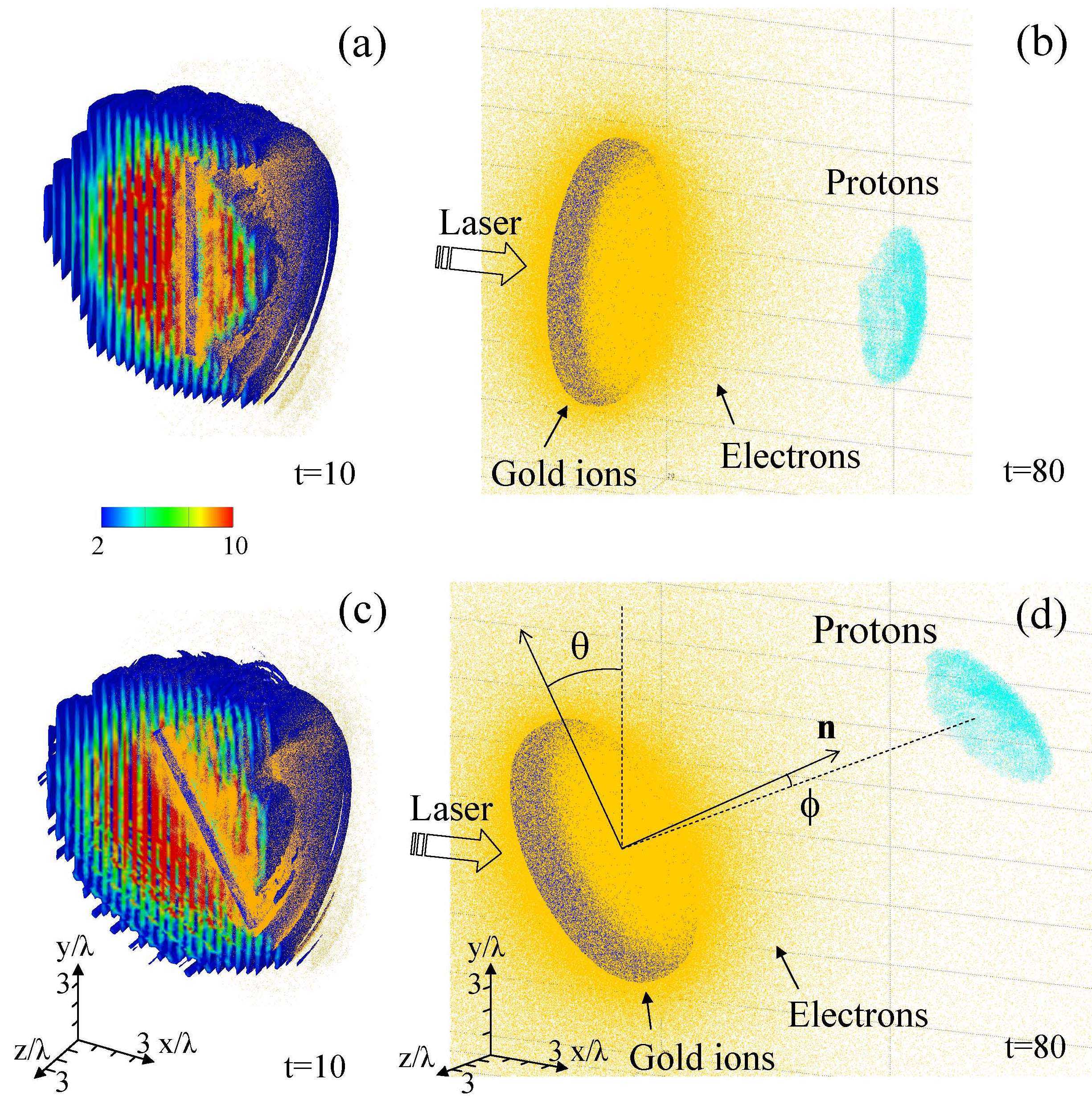
Figure 1 shows the proton beam acceleration for two cases of normal and oblique incidence. For the present simulation parameters, the target is partially transparent for the electromagnetic wave (due to the relativistic transparency effect), which, according to Refs. ESI and EYT , corresponds to an optimal condition of the ion acceleration. In the case of oblique incidence, a substantially larger portion of the electrons is blown off the target due to the effect of ”vacuum heating.”
In order to examine the dependence of the energy achieved by the protons on the incidence angle, , we performed extensive 2D and 3D PIC simulations. Fig. 2 shows the proton energy as a function of the laser pulse incidence angle, normalized by the maximum achievable energy. We see that the maximum proton energy is reached at the incidence angle approximately equal to 30o, for which case we undertook 3D PIC simulation shown in Fig. 1(c,d). The proton energy value is approximately doubled at =30o compared to the case of normal incidence, =0o. This also can be seen in the inset in Fig. 2 showing the proton energy spectra at t=80. While the proton energy increased from 20 MeV at normal incidence to 45 MeV at oblique incidence with an optimal angle, the energy spread is also increased from 10% to 23%.
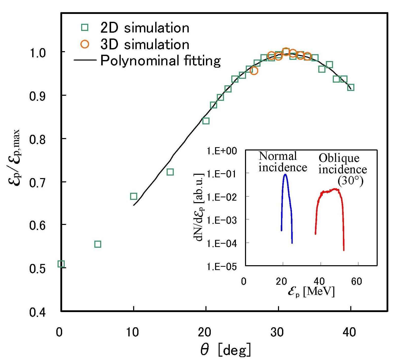
If we invoke the above mentioned ”vacuum heating” mechanism for the laser pulse energy transformation into the electron component energy, and then, via acceleration in the electric field of the charge separation, into the energy of fast protons, we find that the laser pulse energy deposited to the target and the efficiency of pushing the electrons out from the target depend on the incidence angle . The counterplay between these two effects leads to the formation of the fast proton energy maximum at a certain incidence angle. Under the conditions of our simulations this angle is approximately equal to 30o. The analysis of the time evolution of the proton energy spectrum shows that both the average energy and energy spread increase with time. The energy spread appears to grow in the oblique incidence case, which can be accounted for by the asymmetry of the quasistatic electric field along the target surface at oblique incidence. We note that, according to Ref. DL , the energy spread can be decreased by reducing the thickness and transverse size of the low-Z ion (proton) layer.
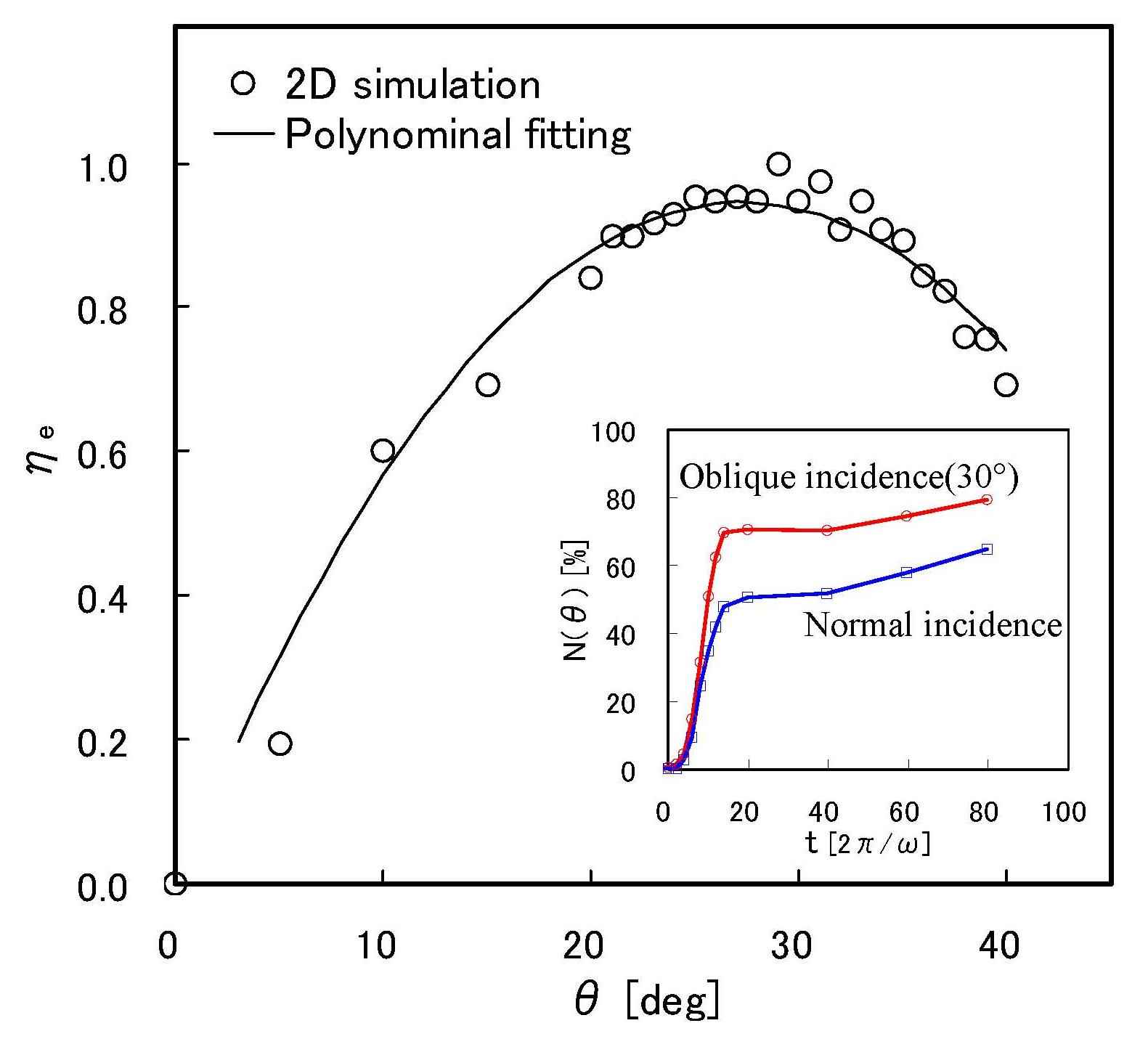
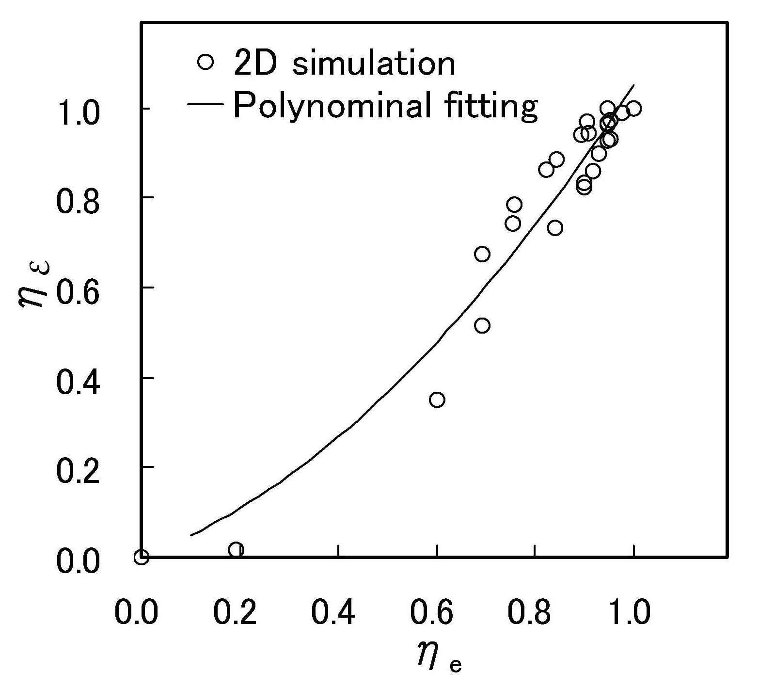
Since the proton acceleration occurs due to the electric field generation through the electron ejection from the target, it is important to analyze the dependence of the number of the electrons leaving the target under the laser radiation action on the incidence angle. Figure 3 shows the ratio of electrons pushed out from the target versus the incidence angle at time t=20. The dependence at t=20 is chosen because at this time the number of ejected electrons saturates as seen in the inset in Fig. 3. The ratio of ejected electrons as a function of the incidence angle is defined by the expression , where is the number of ejected electrons, and are the maximum and minimum values, respectively. We see that this ratio reaches its maximum at the incidence angle about 30o, which evidences a strong correlation between the dependences of the number of ejected electrons (Fig. 3) and the proton energy (Fig. 2) on the laser pulse incidence angle. We see from Fig. 3 that the efficiency of the electron ejection is substantially higher for =30o than in the case of normal incidence. As a consequence, a stronger electric field is produced and the protons are accelerated to higher energy. This is also illustrated in Fig. 4, by the correlation between the average proton energy and the ejected electron number. Here the proton energy ratio at is defined by the expression , where is the average proton energy, and are the maximum and minimum values, respectively. We see that the fast proton energy is roughly proportional to the number of ejected electrons.
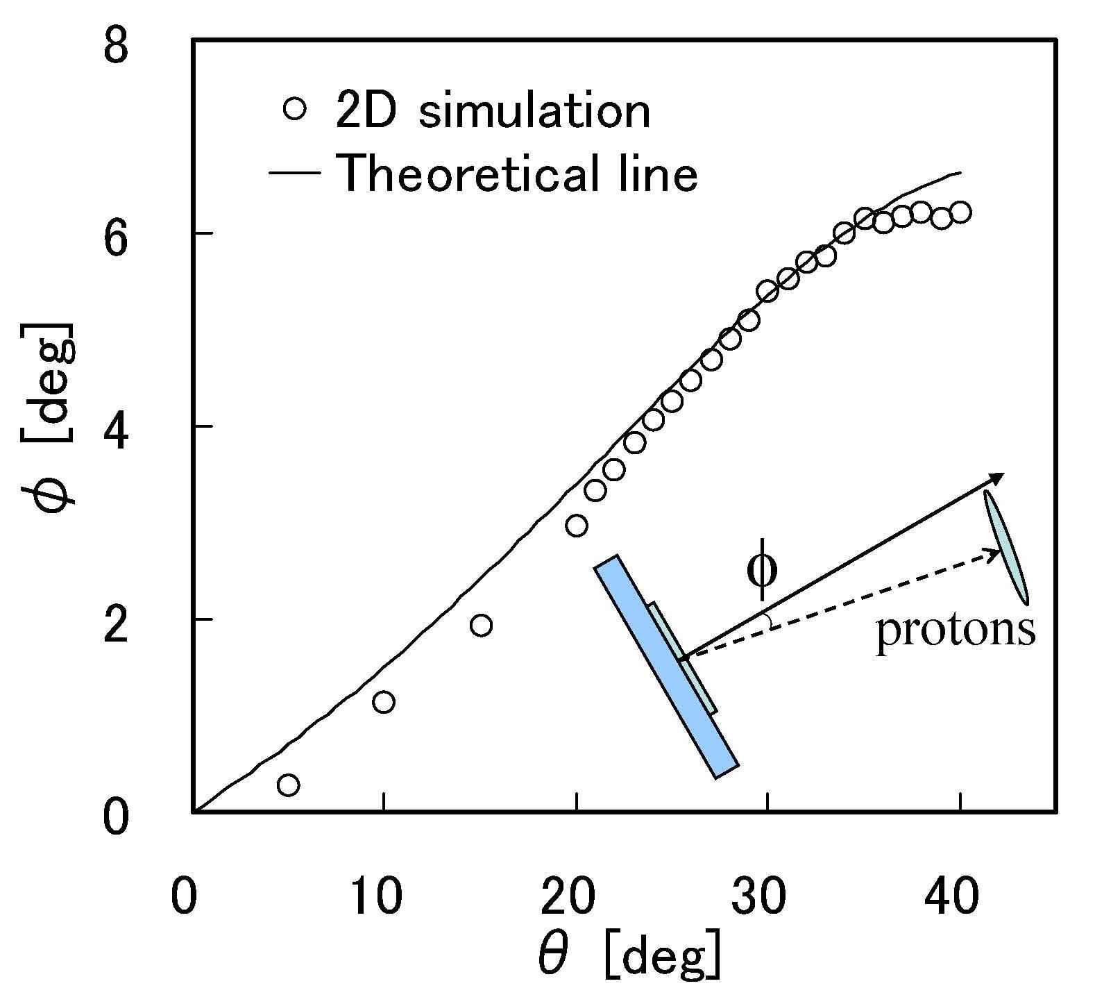
As seen from Fig. 1, the accelerated proton bunch retains the form of the disk. In the case of the normal incidence, the proton disk moves in the direction normal to the target surface while its surface remains parallel to the first (high-Z ion) layer. In the case of oblique incidence, the proton disk motion direction deflects from the target normal by a noticeable angle, , while the disk surface is tilted with respect to the high-Z ion layer, Fig. 1(d). We note that a deflection of the accelerated proton bunch has been observed in the experiments on the laser - solid target interaction Zepf . Under the conditions of our simulations, which correspond to the relatively higher laser intensity, the deflection and tilt can be explained by relativistic effects. As is known, the Lorentz transformation to the frame of reference moving with the velocity along the target surface, i.e. the gamma factor is given by , changes the configuration of the wave–target interaction from oblique to normal incidence BOUR , so that the wave frequency and wave vector of the incident electromagnetic wave become and , where is the unit vector along . In this new boosted reference frame, the protons have a transverse component of momentum equal to , where is the proton mass. As a result of the acceleration in the electric charge separation field, the protons acquire the longitudinal momentum and their energy becomes equal to . Performing the Lorentz transformation back to the laboratory reference frame, we obtain that , and the deflection angle is equal to
| (1) |
In the limit , which corresponds to the parameters of our simulations, this expression yields . For , the angle becomes , i.e. the protons are accelerated almost along the laser pulse propagation direction.
In order to account for the proton disk tilting, we note that the obliquely incident laser pulse front propagates along the target surface with a superluminal velocity . The time delay between moments when different disk elements separated by the distance start to move is equal to . The displacement of the proton layer elements in the direction of the target normal can be estimated as . This gives the angle of the proton disc tilt, , i.e. . This effect is seen in the simulations at an early time of the proton acceleration. Later, higher dimensional effects come into play and the tilting angle changes.
The dependence of the angle of the deflection of the proton motion from the target normal, , on the laser pulse incidence angle, , is seen in Fig. 5. Here the deflection angle, , is defined as the angle between the normal to the target surface placed at the target center and the average radius-vector from the target center to the proton layer, which equals , where is the radius-vector of the -th proton out of protons in the accelerated beam. As seen from Eq. (1), in the limit of a small incidence angle, , the proton bunch is accelerated almost along the direction normal to the target with being a linear function of . When the incidence angle, , increases, the growth of the deflection angle, , saturates, in agreement with the results of simulations, shown in Fig. 2.
In conclusion, we have found that the proton acceleration during laser pulse interaction with double-layer targets is more efficient for oblique incidence than for normal incidence. It is shown that the proton beam energy reaches its maximum at a certain incidence angle of the laser pulse, where it can be much greater than the energy at normal incidence. The proton beam propagates at some angle with respect to the target surface normal, as determined by the proton energy and the incidence angle. In the limit of nonrelativistic proton energy, the deflection angle is relatively small. However, its value (see Fig. 5) results in the proton beam deflection of the order of 10 cm after the protons have propagated over 1 m distance. Therefore this angle should be taken into account in the real facility design to make proper mutual location of the proton source and the target. This provides a way to control the proton energy and the direction of the proton beam propagation by adjusting the incidence angle of the laser pulse. Such flexibility and speed in controlling the proton directionality and energy will be invaluable for conformal cancer therapy treatments such as pixel scanning using heavy ions HBS .
Two of authors (S.V.Bulanov,T.Zh.Esirkepov) thank O.Willi for useful discussions. This work was in part supported by JST/CREST and MEXT. The computation was done with the ES40 at JAEA Kansai and ALTIX 3700 at JAEA Tokai.
References
- (1) V. I. Veksler, Atomic Energy 2, 427 (1957); A. G. Gurevich, et al., Sov. Phys. JETP 22, 449 (1966); J. E. Gunn and J. P. Ostriker, Phys. Rev. Lett. 22, 728 (1969).
- (2) E. L. Clark, et al., Phys. Rev. Lett. 84, 6703 (2000); A. Maksimchuk, et al., Phys. Rev. Lett. 84 4108 (2000); R. A. Snavely, et al. Phys. Rev. Lett. 85, 2945 (2000); K. Matsukado, et al., Phys. Rev. Lett. 91, 215001 (2003); J. Fuchs, et al., Nature Phys. 2, 48 (2006).
- (3) C.-M. Ma, et al., Med. Phys. 28 1236 (2001); S. V. Bulanov, et al., Phys. Lett. A 299, 240 (2002); V. Malka, et al., Med. Phys. 31, 1587 (2004).
- (4) M. Roth, et al., Phys. Rev. Lett. 86, 436 (2001); V. Yu. Bychenkov, et al., Plasma Phys. Rep. 27, 1017 (2001); S. Atzeni, et al., Nucl. Fusion 42, L1 (2002).
- (5) I. Spencer, et al., Nucl. Instrum. Methods Phys. Res. B 183, 449 (2001); S. Fritzler, et al. Appl. Phys. Lett. 83, 3039 (2003).
- (6) K. W. D. Ledingham, et al., J. Phys. D 36, L79 (2003).
- (7) T. Zh. Esirkepov, et al., Phys. Rev. Lett. 92, 175003 (2004).
- (8) K. Krushelnick, et al., IEEE Trans. Plasma Sci. 28, 1184 (2000).
- (9) M. Borghesi, et al., Phys. Plasmas 9, 2214 (2002).
- (10) S. V. Bulanov, et al., Nucl. Instrum. Methods Phys. Res. A 540, 25 (2005).
- (11) M. Borghesi, et al., Fusion Science and Technology 49, 412 (2006); G. Mourou, et al., Rev. Mod. Phys. 78, 309 (2006); S. V. Bulanov, Plasma Phys. Control. Fusion 48, B29 (2006).
- (12) S. V. Bulanov and V. S. Khoroshkov, Plasma Phys. Rep. 28, 453 (2002).
- (13) T. Zh. Esirkepov, et al. Phys. Rev. Lett. 89, 175003 (2002).
- (14) T. Zh. Esirkepov, et al., Phys. Rev. Lett. 96, 105001 (2006).
- (15) C. Schwoerer, et al., Nature 439, 445 (2006).
- (16) R. Sonobe, et al. Phys. Plasmas 12, 073104 (2005); T. Okada, et al. Phys. Rev. E 74, 026401 (2006).
- (17) V. F. D’yachenko and V. S. Imshennik, Sov. J. Plasma phys. 5, 413 (1979); F. Brunel, Phys. Rev. Lett. 59, 52 (1987).
- (18) C. K. Birdsall and A. B. Langdon, Plasma Physics Via Computer Simulation, McGraw-Hill, New York (1985).
- (19) M. Zepf, et al., Phys. Rev. Lett. 90, 064801 (2003); F. Lindau, et al., Phys. Rev. Lett. 95, 175002 (2005); P. McKenna, et al., Phil. Trans. R. Soc. A 364, 711 (2006).
- (20) A. Bourdier, Phys. Fluids 26, 1804 (1983).
- (21) Th. Haberer, et al., Nucl. Instr. Met. A 330, 296 (1993).