Optomechanical trapping and cooling of partially transparent mirrors
Abstract
We consider the radiative trapping and cooling of a partially transmitting mirror suspended inside an optical cavity, generalizing the case of a perfectly reflecting mirror previously considered [M. Bhattacharya and P. Meystre, Phys. Rev. Lett. 99, 073601 (2007)]. This configuration was recently used in an experiment to cool a nanometers-thick membrane [Thompson et al., arXiv:0707.1724v2, 2007]. The self-consistent cavity field modes of this system depend strongly on the position of the middle mirror, leading to important qualitative differences in the radiation pressure effects: in one case, the situation is similar that of a perfectly reflecting middle mirror, with only minor quantitative modifications. In addition, we also identify a range of mirror positions for which the radiation-mirror coupling becomes purely dispersive and the back-action effects that usually lead to cooling are absent, although the mirror can still be optically trapped. The existence of these two regimes leads us to propose a bichromatic scheme that optimizes the cooling and trapping of partially transmissive mirrors.
pacs:
42.50.Pq, 04.80.Nn, 42.65.Sf, 85.85.+jI Introduction
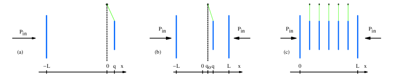
The optomechanical cooling and trapping of mirrors has recently become the subject of an intense research effort as it promises to offer a viable means of extending quantum mechanics to macroscopic objects gig ; kle ; arc ; sch ; cor . The typical experimental arrangement consists of a linear two-mirror optical cavity (2MC) driven by laser radiation close to a cavity resonance [Fig.1(a)]. One of the mirrors in the cavity is small and is mounted on a cantilever, so as to be movable, and the goal is to cool its vibrational state of motion to a point as close to its quantum mechanical ground state as possible. The cooling proceeds with the use of two laser beams, the first one detuned to the blue of a cavity resonance and providing an optical trap for the movable mirror, with a frequency larger than the intrinsic cantilever frequency ; and the second one detuned to the red of the cavity, so as to (almost) independently increase the damping constant of the oscillating mirror from its field-free value to cor .
From the quantum mechanical point of view, the combined effect of the laser fields on the moving mirror is two-fold: they create a harmonic trap with large energy level spacing , and cool the mirror from its initial equilibrium temperature to a lower value
| (1) |
as shown explicitly in Appendix A. The trapping and cooling effects thus lower the number of quanta of vibrational excitation of the oscillating mirror to
| (2) |
where is Boltzmann’s constant. Current experimental effort is intensely focused at achieving , i.e. at placing the mirror in its quantum mechanical ground state. We note at the outset that the expression for given in Ref. mis includes an additional term as compared to Eq. (2). That additional term results from expressing in terms of the ‘bare’ oscillation frequency of the moving mirror rather than its effective frequency and underestimates its degree of excitation. The correct formula is Eq. (2) of this article. However the correction does not bring any qualitative change to the conclusions of the earlier work, Ref.mis . The same correction has recently been realized by other authors kar (a); mar .
In the 2MC the allowed laser power is limited by the onset of mirror bistability dor , placing bounds on the achievable cooling and trapping. In addition, in that geometry radiation pressure is not used optimally as it couples to the mirror from one side only. Most importantly perhaps, the 2MC requires the movable mirror to be one of the end-mirrors of a high finesse cavity and to have a high mechanical quality as well. Technically these are conflicting demands because the high finesse that maximizes the cooling effect of radiation is best achievable with massive, rigidly fixed mirrors. On the other hand, the high mechanical quality that minimizes the oscillator’s coupling to thermal noise is best achievable with small, flexibly mounted mirrors. These opposing requirements represent the main experimental challenge to achieving states of vibration of low quantum number in the 2MC.
In a recent article we proposed an alternative geometry that allows one to reach and detect lower ’s for comparable parameters mis by suspending a perfectly reflecting mirror in the middle of a two-mirror cavity [Fig.1(b)]. This three-mirror cavity (3MC) arrangement was shown to possess at least three advantages over the 2MC. First, it provides a higher value of for the mirror pm (1); kha ; vog ; she , leading to fewer quanta of excitation, see Eq. (2). Second it removes bistability problems completely as far as the trapping fields are concerned, and partially for the cooling fields. Lastly, it increases the time available for observing the quantum dynamics of the mirror before the onset of thermal decoherence.
The present paper generalizes the analysis of the 3MC to the case where the middle mirror is partially transmitting, with the goal of determining to what extent its advantages are retained in that case, and also as a first step toward determining whether the same linear cavity can be used to quantize the motion of more than one mirror, see [Fig.1(c)]. A classical treatment of the 3MC was presented earlier pm (1), however the noise analysis did not include the vacuum fluctuations in the laser fields and and were derived only in the static (zero-frequency) limit. Since we are concerned with cooling the movable mirror to its quantum mechanical ground state, a full quantized treatment is clearly needed. We derive expressions for the effective frequency and damping constant valid for any frequency , and in making contact with the case of the perfectly reflecting middle mirror we include details that could not be presented in Ref. mis for lack of space.
In the course of concluding this work we became aware of a recent experiment that beautifully demonstrates the working of the 3MC and points out some of its additional virtues tho . In that work Thompson et al. cooled a 50nm thick dielectric membrane placed inside an optical cavity from room temperature (294K) down to 6.82mK, i.e. by a factor of . These authors also pointed out that the 3MC solves a number of the technological challenges faced by the 2MC as it allocates the requirements of high optical finesse and high mechanical quality to different parts of the cavity. The high finesse optical cavity now consists of two rigidly fixed mirrors, while the suspended middle mirror (or membrane) can independently have a high mechanical quality. Additionally the 2MC only allows the measurement of the mirror displacement , while the 3MC allows the measurement of , thereby projecting the state of the mirror into an energy eigenstate bra .
Rather than elaborating on the salient features of Ref. tho , this paper examines the effect of middle-mirror transparency on the bistability, effective trapping frequency and damping displayed by the 3MC. Our model is comprehensive in that it is valid for a totally as well as for a partially reflecting mirror and also for an arbitrary placement of the moving mirror inside the cavity. The consideration of various limiting cases allows us to propose a new two-color scheme that optimizes the cooling and trapping of the transparent mirror. We note that issues similar to those considered in this work have recently been presented in Ref. kar (b) using a different formalism.
The paper is organized as follows. Section II derives a Hamiltonian of the moving mirror-cavity system valid in situations where it is sufficient to consider two modes of the cavity field, and Section III shows how that Hamiltonian reduces to the case of a perfectly reflecting middle mirror mis . We then turn to the case of a finite transmission, with Section IV discussing the situation when the moving mirror location yields a linear coupling to the photon number difference in the two field modes, and Section V to the case where that coupling becomes quadratic. Section VI discusses the modification of the oscillation frequency and damping rate of the mirror by radiation pressure, Section VII applies these results to the formulation of a proposal for a new trapping and cooling configuration, and Section VIII is a summary and conclusion. Appendix A contains a careful derivation of Eqs.(1) and (2), and appendices B and C present details of the cases considered in Sections IV and V.
II Model Hamiltonian
We consider a 3MC geometry with the outer mirrors fixed at [Fig.1(b)] and a middle mirror of transmissivity located at a position . We assume the mirror thickness to be much smaller than an optical wavelength, a condition that has been realized experimentally tho .
II.1 Classical modes
We proceed by first determining the mode frequencies of the full resonator as a function of and . In the simple case the resonant frequencies of the two sub-cavities are
| (3) |
where
| (4) |
and is the mode number (Table 1).
When , the two sides of the resonator are coupled and the modes of the complete system are found by solving the Helmholtz equation with the appropriate boundary conditions at , as described in Ref. Fader (1985). For this calculation we assume for simplicity that the mirrors at are perfectly reflecting. We also consider high-order cavity modes such that and mirror displacements (modulo . The finite transmission of the end-mirrors will be accounted for later on.
Carrying through the classical calculation the wave vectors supported by the full resonator appear as solutions to the transcendental equation Fader (1985)
| (5) |
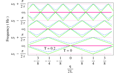
The solutions of Eq. (5) imply that as a result of the coupling between the two sub-cavities of the resonator each pair of initially two-fold degenerate modes of frequency splits into a pair of non-degenerate modes, see Fig. 2,
where
| (7) |
is the round trip time for each sub-cavity, assumed to be approximately the same for both sides of the resonator for and . In Eq. (II.1) corresponds to a mode with an even number of half wavelengths in the full resonator, while the mode at frequency has an additional half-wavelength, hence a slightly higher frequency. It corresponds to a field maximum at the center of the resonator, and turns into a ‘cosine’ mode in the limit , while the even mode of frequency turns into a ‘sine’ mode in that limit. The electromagnetic fields corresponding to the frequencies in Eq. (II.1) can be found in Refs. Chow (1986); cho . In these references it is noted that due to the presence of a ‘dielectric bump’ at the middle mirror the fields have a discontinuity in their derivative at that position.
II.2 Quantization
Sections III-VI concentrate on an analysis restricted to the modes and about a specific (Table 1). We quantize these two modes under the assumption that the oscillation frequency of the middle mirror is sufficiently small that , so that the electromagnetic field frequencies follow adiabatically the mirror motion, and and are simply parameterized by the mirror position . The Hamiltonian of the coupled field-mirror system is then
| (8) |
where we have dropped the subscript for clarity, and are bosonic field operators for the modes of instantaneous frequencies and satisfying the commutation relations
| (9) |
and are the momentum and position operators of the moving mirror, with
| (10) |
and is its rest position in the absence of radiation. The radiation pressure that couples the mirror motion to the resonator field is implicitly contained in the position dependence of and , see Eqs. (II.1), as we will see shortly when considering various limits of the Hamiltonian [Eq. (8)].
III Perfectly reflecting middle mirror
For a perfectly reflecting middle mirror, , the even and odd mode frequencies of Eqs. (II.1) reduce to the eigenfrequencies of the left and right sub-cavities of the 3MC
| (11) |
respectively. These frequencies are shown as the solid red see-saw lines in Fig. 2. For the Hamiltonian (8) can then readily be reexpressed as
| (12) |
where
| (13) |
is the optomechanical coupling parameter and and are annihilation operators for the optical modes in the left and right sub-cavities (Fig.1(c) in mis ). In this form, the Hamiltonian (12) shows explicitly the effect of radiation pressure on the mirror motion. It is the form used in particular to discuss mirror cooling in Ref. mis .
We note that the Hamiltonian (12) also holds for after a trivial change of coordinate . Physically, this indicates that displacing the rest position of the moving mirror from the center of the resonator causes no qualitative change in its dynamics. In particular the radiation pressure term remains linear in the mirror position (again under the assumption that ), and the cooling and trapping behavior is essentially the same as discussed in Ref. mis . The situation is significantly different for the case , as we now discuss 111We also note that the experimental arrangement corresponding to this model is that of the 3MC irradiated from both sides mis , see Fig.1(b). In this case both end-mirrors have a small transmissivity (Table 1)..
IV , linear coupling
As illustrated in Fig. 2, the coupling between the two sub-cavities resulting from the finite transmission of the moving mirror leads to the appearance of a series of avoided crossings between and near those points where either is doubly degenerate for , or two frequencies and become degenerate. The slopes of the solid see-saw lines in Fig. 2 are given by and are therefore -dependent, hence the anti-crossing points are not equidistant. For large enough , though, and the avoided crossings occur for mirror separations from , where is an integer and is some typical wavelength about .
To lowest order, the dependence of and on is linear away from the anti-crossings, but quadratic in their vicinity. Hence we expect the radiation pressure contribution to the Hamiltonian (8) to be likewise linear and quadratic respectively, in these two cases.
Consider first the linear case where and the rest position of the moving mirror is away from any anti-crossing point. For small enough mirror displacements, , we expand and about to find
| (14) |
where
and
| (17) |
is a generalized linear optomechanical coupling parameter. It is easy to verify that for . When , for , where is an integer. This has important consequences that we discuss later on. A plot of is given in appendix C, Fig. 5.
With Eqs. (IV) the Hamiltonian (8) becomes
or, with ,
| (19) | |||||
We note that this Hamiltonian is not equivalent to setting , since Eq. (IV) would then imply that , and the radiation-mirror coupling would vanish.
Comparing Eqs. (12) and (19) shows that in the linear coupling regime, the finite mirror transmission results in the frequencies of the two modes being shifted by and , respectively, and the optomechanical constant being redefined as . However, since the coupling of the radiation with the mirror remains linear there is no significant qualitative difference between the cooling and trapping mechanisms in the two cases.
Appendix C shows that a simple transformation can put the dynamical equations for the Hamiltonian Eq. (19) in a form identical to those for Eq. (12), with replaced by and absorbed as detuning shifts. In that same appendix we show that for an appropriate placement of the mirror we can obtain . Hence it should be possible to trap and cool the partially transparent moving mirror to its quantum mechanical ground state with essentially the same parameters as the perfectly reflecting mirror. In Table 1 we present such a set of parameters. Another set of parameters has been suggested in Ref. tho .
V , quadratic coupling
We now turn to the situation where the middle mirror is placed at a position ( integer). In that case, expanding Eqs. (II.1) to lowest order about gives
| (20) |
where the detuning
| (21) |
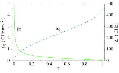
and the quadratic optomechanical coupling constant is
| (22) |
The detuning and are plotted in Fig. 3 as functions of .
The Hamiltonian (8) now becomes
Since and are independent of we can rescale that Hamiltonian by the transformation without affecting any of the physics. This is equivalent to setting and yields
| (24) | |||||
As expected from our previous discussion, the mirror-radiation coupling is now quadratic in the mirror coordinate, in contrast to Eqs.(12) and (19), where it is linear tho . This coupling is purely dispersive and leads to qualitatively different radiation effects. We show below that such a coupling implies in particular the ability to trap but not cool the moving mirror.
VI Effective frequency and damping
VI.1 Quantum Langevin Equations
We consider for concreteness a simple implementation of the 3MC trapping and cooling scheme where the system is driven by a narrow-band laser field of frequency impinging on the resonator from the left, the right end-mirror being assumed to be perfectly reflecting. As previously discussed cor , two lasers of different frequencies have to be used in practice to control the moving mirror. Except for the fact that the powers and frequencies of these two fields must be chosen self-consistently in order to ensure the dynamic stability of the system, one of them essentially affects solely the spring frequency and the other only the spring damping, so we consider them separately in the following.
At this point we introduce an additional simplification by noting that for the value of considered here we have , (Table 1), that is, the frequency separation of the two modes is much larger than the cavity linewidth. In that case, and provided that the laser linewidth is comparable to or less than , it is sufficient to consider a single-mode treatment that involves only the resonator mode closest to .
By inspection of the last term in Eq. (24) we expect that the ‘’ mode will cause anti-trapping since it is associated with a negative ‘spring constant’ while the mode ‘’ should lead to mirror trapping. Tuning the laser to the frequency of the latter mode yields then the approximate single-mode Hamiltonian
| (25) |
which we analyze below.
The fluctuations of the electromagnetic vacuum couple into the resonator through the partially transmitting input mirror, which also leads to the damping of the intracavity field. Further the Brownian noise associated with the coupling of the oscillating mirror to its thermal environment must be accounted for in a realistic treatment of the mirror dynamics. We describe the effect of these sources of noise and dissipation within the input-output formalism of quantum optics Gardiner (1991). For the Hamiltonian (25) this yields in a standard fashion the nonlinear quantum Langevin equations
| (26) |
where the detuning is given by
| (28) |
and
| (29) |
is the decay rate through the input mirror of transmissivity (Table 1).
In Eq. (VI.1) the noise operator describes the field pumping the cavity mode. It is characterized by the semiclassical mean value
| (30) |
and Markovian fluctuations
| (31) |
The Brownian noise operator describes the heating of the mirror by its thermal environment. It is characterized by a zero mean value, and fluctuations at temperature correlated as Gardiner (1991)
| (32) |
For the parameters of our model, , and therefore the high-temperature limit of Eq. (VI.1),
| (33) |
is applicable.
VI.2 Steady state
Appendix C shows that for any value of , is the only real steady-state solution for the mirror displacement. In contrast to standard configurations bistability does not occur because we have chosen a trapping mode for the mirror. The steady-state of the mirror-cavity system is given by
where is the amplitude of the laser field pumping the cavity. The phase of this field can be chosen without loss of generality such that is real. The steady-state intracavity field mode amplitude in Eq. (VI.2) is independent of , a consequence of the fact that .
VI.3 Fluctuations
To account for the effect of the classical and quantum fluctuations we decompose each operator in Eq. (VI.1) as the sum of its steady-state value and a small fluctuation, e.g. . Substituting these quantities into Eq. (VI.1), eliminating the steady-state contribution and linearizing the resulting equations for the fluctuations we have
| (35) |
Here the vectors of the input noise and fluctuations are respectively given by
| (36) |
and we have symmetrized the fluctuation operators as , , etc. The matrix is given explicitly by
| (37) |
The steady-state solutions (VI.2) are dynamically stable if none of the eigenvalues of the matrix has a positive real part. This condition can be quantified in terms of the Routh-Hurwitz criterion dej , which yields inequalities too involved to be presented here. However, we will work at in the following and it is quite easy to show analytically that for this detuning and any value of the other parameters of Eq.(37) there is no dynamical instability in the 3MC.
VI.4 Effective frequency and damping
In order to determine the effective frequency and damping of the mirror in the regime of quadratic coupling, Eq. (25), we solve the linearized quantum Langevin equations for the fluctuations in the mirror position,
| (38) |
where is the mechanical susceptibility of the mirror and , which describes the fluctuations in the total force on the mirror, consists of a radiation vacuum and a Brownian motion component. The susceptibility has the form of a Lorentzian coh
| (39) |
from which we can extract the effective oscillation frequency and damping constant of the mirror as
| (40) |
where is the input power of the incident laser. Strikingly, is unchanged from its intrinsic value, signifying the absence of the usual back-action effects responsible for mirror damping. Specifically we see that if we retain only terms linear in the fluctuations the quadratic optomechanical coupling of Eq. (24) does not affect the damping of the mirror. This is because the radiation-mirror coupling is purely dispersive, as pointed out in Ref. tho .
The modification of the mirror frequency in Eq. (VI.4) is a result of the dependence of the cavity mode frequencies on the position of the moving mirror. Radiation pressure trapping translates into an increase of the effective mirror frequency from its ‘bare’ value . It follows from Eq. (VI.4) that the mirror can be optically trapped by selectively exciting the mode , and that the trapping effect is strongest on resonance , with the resulting trapping frequency
| (41) |
For this configuration there is neither (static) bistability nor dynamical instability, hence a high laser power can be used to achieve tight mirror traps, limited only by the effects of mirror heating.
In Eq. (VI.4) the effective frequency depends on the mirror transmissivity through the coupling parameter [Eq. (22)] which can be large for small values of as evident from Fig. 3. For the parameters of this paper the effective frequency turns out to be much larger than the bare mechanical frequency (see below) and it is comparable to the effective frequency achieved in the 3MC with a perfectly reflecting middle mirror (Eq. (7) in Ref. mis ). However, the trapping light does not introduce any anti-damping in the present case, in contrast to both the situation and the linear coupling regime described by the Hamiltonian (19).
For completeness we mention that an equivalent single-mode treatment of the coupling of the incident laser into the even mode of frequency leads to anti-trapping and instabilities, both static as well as dynamic. We do not consider this regime further in this paper.
VII Bichromatic trapping and cooling
Summarizing our results so far, we have shown in Section IV and Appendix B that in the regime of linear optomechanical coupling an even mode can be used to achieve passive cooling, while Section VI.4 demonstrates the possibility of achieving a large effective frequency without introducing any anti-damping in the regime of quadratic optomechanical coupling. These results suggest the use of two incident lasers at wavelengths and that drive the mirror in the linear and quadratic coupling regimes, respectively, to damp and trap its motion, see Fig. 4. These wavelengths are chosen such that the corresponding resonant cavity mode numbers so that . We also assume that each incident laser is effectively coupled to only one cavity mode so that the single mode treatments of sections VI.4 and IV and appendix B are valid. In order for the two lasers to act essentially independently on the moving mirror we also require that they couple into resonator modes whose frequency separation is much larger than .
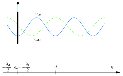
The dependence of the frequencies and of the two relevant cavity modes on the mirror position is as illustrated in Fig. 2, but with the mutual shift in position shown schematically in Fig. 4. The moving mirror is at a position such that has an extremum (the first minimum to the left of , at in Fig. 4.). The laser excitation of that mode results in mirror trapping with no anti-damping, as we have seen.
The first maximum of is at from the cavity center, hence the mirror is at a distance to the right of that maximum, see Fig. 4. Appendix B shows that regular passive cooling can be implemented by red-detuning the radiation from , and that in order to optimize radiation effects for the mirror should be displaced by an amount of the order of to the right of the maximum of , (Fig.5). This implies
| (42) |
which gives for the example of Fig. 4. In an actual experiment, an appropriate can be found empirically given two available laser wavelengths.
This ‘hybrid’ configuration enables a trap stiffness unrestricted by considerations of anti-damping. In other words the trapping light at does not destabilize or raise the noise temperature of the middle mirror at all. This technique is therefore superior to the standard trapping and cooling scheme based only on a radiation-mirror coupling linear in the mirror coordinate, such as Eqs. (12) or (19). Both the effective mirror damping (due to absence of anti-damping) as well as the mirror trapping (due to absence of instabilities) can be stronger in the hybrid case, and the achievable final degree of vibrational excitation [Eq. (2)] is therefore lower.
For example, if anti-damping is absent in the case of purely linear coupling treated in appendix B, the total damping increases by a factor of , implying a mirror temperature lower by the same factor. The trapping required to reach the ground state now can be achieved by 8mW of laser light on resonance.
VIII Conclusion
The radiative trapping and cooling of a totally or partially reflecting mirror in an optical cavity has been considered theoretically. Our main conclusion is that allowing the middle mirror to be quite transmissive does not greatly affect the ability of radiation to cool the mirror down to its quantum mechanical ground state. In fact the parameters required to accomplish ground state occupation for the transparent mirror are virtually the same as for a perfectly reflecting mirror. For this reason the advantages of the 3MC over the 2MC mentioned in Ref. mis are retained even if the middle mirror is allowed to be a little transparent.
We have shown that the nature of the mirror-radiation interaction can be changed from dissipative to dispersive depending on the position of the middle mirror with respect to the end mirrors of the cavity, in agreement with the analysis of Ref. tho , and also that in the dispersive regime strong optical trapping of the mirror is possible without any anti-damping.
Combining the various regimes of optomechanical coupling that we have identified, we have also proposed a novel two-color mirror trapping and cooling scheme based on positioning the mirror so as to simultaneously couple it dissipatively with one cavity mode and dispersively with a second mode. In contrast to all the configurations implemented or discussed in the literature so far, trapping in this configuration does not cause anti-damping or instabilities of either the static or dynamic kind. This improves the damping effect of radiation while allowing for tighter mirror traps to be established using higher laser power. This allows to reach lower mirror temperatures and eases the route to the occupation of the quantum mechanical ground state of the moving mirror.
| No. | Parameter | Description | Value | Units |
|---|---|---|---|---|
| 1. | sub-cavity length | 5 | mm | |
| 2. | laser wavelength | 514 | m | |
| 3. | mode number | 104 | - | |
| 4. | cavity resonance frequency | 21015 | Hz | |
| 5. | optomechanical coupling parameter | 100 | MHz nm-1 | |
| 6. | linear optomechanical coupling | 100 | MHz nm-1 | |
| 7. | middle mirror transmissivity | 10-4 | - | |
| 8. | mode frequency shift | 1 | GHz | |
| 9. | quadratic optomechanical coupling | 100 | MHz nm-2 | |
| 10. | middle mirror mass | 1 | g | |
| 11. | middle mirror resonance frequency | 22.5 | kHz | |
| 12. | middle mirror damping constant | 0.02 | g Hz | |
| 13. | middle mirror initial temperature | 300 | K | |
| 14. | end mirror transmissivity | 10-5 | - | |
| 15. | cavity linewidth | 25 | MHz |
Acknowledgements.
This work is supported in part by the US Office of Naval Research, by the National Science Foundation and by the US Army Research Office. We thank O. Dutta, Dr. C. Maes and Prof. H. Ritsch for useful discussions.Appendix A Effective temperature and quanta
This Appendix derives Eqs. (1) and (2) and discusses their limit of validity. We mention here a correction to Eq.(1) of Ref. mis which presented an incorrect scaling of the mirror quanta with effective frequency, and thus underestimated the degree of excitation of the mirror. This correction however does not bring any qualitative change to our previous results mis . That same correction has recently been realized by other authors kar (a); mar .
The starting point of our derivation is Eq. (38). For the parameters of the model discussed in Sections III, IV and V, the fluctuations in the total force are due mainly to thermal noise, so that . In the case of Section V this is exactly true i.e. since fluctuations in the radiation field do not couple to the mirror motion in the framework of linear response theory. In either case the two-time correlation function of the force fluctuations is therefore that of the thermal component,
| (43) |
where according to Eq. (33).
Fourier transforming (FT) both sides of Eq. (43) using the symmetric FT
| (44) |
gives the frequency-domain correlation function
| (45) |
which in turn allows us to express the correlation function for the linear displacement, see Eq. (38), as
| (46) |
Inverse Fourier transforming both sides of Eq. (46) we get
| (47) |
since from Eqs. (39), (VI.4) and (B). Setting in Eq. (47) we get
| (48) |
We now use the equipartition theorem to link the average displacement squared to , the effective temperature of the vibrating mirror
| (49) |
Note that the equipartition theorem is expressed in terms of the effective frequency of the mirror. Combining Eqs.(48) and (49) we find
| (50) |
This allows us to determine the mean number of quanta of vibration of the moving mirror as
| (51) |
where
| (52) |
The exact form of the effective frequency and damping depend on the position and transmission of the middle mirror. They are given by either Eq. (VI.4) or Eq. (B). In the case of Eq. (VI.4) the effective quantities do not depend on . In the case of Eq. (B) we expand them in a Taylor series around and keep only the leading terms in the respective expansions (see below for justification),
| (53) |
With Eq. (A) we find analytically
| (54) |
Equations (50) and (51) then imply
| (55) |
and
| (56) |
respectively. These are precisely Eqs. (1) and (2). Evidently Eqs. (54), (55) and (56) are exact when the effective frequency and damping follow from Eq. (VI.4). (We will say no more about this case.). These results are however approximate when the effective frequency and damping follow from Eq. (B).
To ensure that the approximation stated in Eq. (A) is accurate, we used the full functional forms of and from Eq. (B), and performed the integral in Eq. (54) numerically. For the parameters used in this paper this yields numerical values indistinguishable from the approximate analytical expressions, i.e. we found the same effective temperature and quanta for the mirror.
The condition that needs to be satisfied for the approximation in Eq. (A) to be valid can be found by inspecting the forms of the functions and in Eq. (B). Expanding analytically these expressions in Taylor series about and defining
| (57) |
we find
| (58) |
where
| (59) | |||||
is the first term in the expansion and can be neglected since we are in a regime where the optical contribution to the stiffness is typically much larger than the intrinsic mechanical contribution (this may be translated into an appropriate condition on [Eq. (57)]). The coefficient of the second term in Eq. (58) is
| (60) |
The contribution of the second term becomes comparable to that of the first in Eq. (58) at the critical frequency
| (61) |
Using the hierarchy applicable to this article, we approximate Eq. (61) and get
| (62) |
The detuning is usually a few cavity linewidths for trapping, e.g. in this work. Thus and therefore . Also, for our parameters . This implies that not only is the critical frequency much larger than the intrinsic mechanical frequency, it is also much larger than the optically-induced mirror frequency, an important observation. A similar result can be obtained for , in which case The general conclusion is that for our parameters the higher order frequency-dependent terms in the expansions of and become important at frequencies much higher than .
Now for [from Eq. (A)] the integrand in Eq. (50) is a Lorentzian peaked at , with a symmetric peak at -. The regime then corresponds to the far-out wings of the Lorentzian, since . In this regime the contribution of the higher-order terms to the spectrum is highly suppressed, resulting in virtually no change in the area underneath the spectrum and no change in the scalings in Eqs. (55, 56). Thus the condition under which Eqs. (1) and (2) hold is
| (63) |
which is well satisfied in our case.
Appendix B Linear optomechanical coupling
This appendix discusses the two-mode situation described by the linear coupling Hamiltonian (19), and relates it to the case of a 3MC with perfectly reflecting middle mirror of Ref. mis . We consider specifically the situation where the frequencies of the two resonator modes under consideration are widely separated and are driven by two independent incident lasers of frequencies and .
The quantum Langevin equations for the Hamiltonian of Eq. (19) can be written as
| (64) |
where describes the decay rates of the left and right sub-cavities,, taken to be equal for simplicity, and the frequencies of the two laser have been chosen such that
| (65) |
Equation (B) is exactly the same as Eq. (3) of Ref. mis with the change of notation , hence it yields the same radiation effects.
The effective parameters for the middle mirror can therefore be determined from Eq. (7) of Ref. mis which we reproduce below
| (66) |
Fig. 5 shows that for an appropriate middle mirror position we can have . Even for a mirror transmission as large as tho is possible, indicating that the cooling of the moving mirror to its ground state of vibration is possible both for weakly transparent as well as for perfectly reflecting mirrors using essentially the same parameters. It also follows that the advantages of the 3MC over the 2MC pointed out in Ref. mis are retained even in the case where the middle mirror is partially transparent.
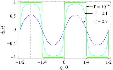
Table 1 lists the relevant numerical values considered in this paper. Using 5mW of trapping light at a detuning and W of cooling light at a detuning we find , and K. Here we have assumed a mechanical quality factor of , an optical finesse of and an ambient temperature of 300K. From Eq. (2), these values imply .
We note that in Eq. (3) of Ref. mis and are the annihilation operators of the modes in the sub-cavities, while in Eq. (B) they correspond to modes of the full resonator; in the case of a finite transmission, both modes need to be pumped to obtain a behavior analogous to that of the 3MC with the perfectly reflective middle mirrors.
Appendix C Steady state solutions and bistability
This appendix considers the bistability of the steady-state solutions in the case of a partially transparent mirror placed in such a way that the resonator frequency is at a minimum, see Eq. (VI.2).
The equations obtained by setting the time derivatives in Eq. (VI.1) equal to zero are
| (68) |
where we have solved for . The value of can be obtained by using the first equation in the last and solving for .
From the last equation we see that is the only real solution for the mirror position. This is because the factor in parentheses is the sum of two positive non-zero terms, and can never equal zero for real . Hence there is no bistability for the single-mode configuration of Section VI.2.
References
- (1) S. Gigan, H. R. Böhm, M. Paternostro, F. Blaser, G. Langer, J. B. Hertzberg, K. C. Schwab, D. Bäuerle, M. Aspelmeyer, and A. Zeilinger, Nature 444, 67 (2006).
- (2) D. Kleckner and D. Bouwmeester, Nature 444, 75 (2006).
- (3) O. Arcizet, P. -F. Cohadon, T. Briant, M. Pinard, and A. Heidmann, Nature 444, 71 (2006).
- (4) A. Schliesser, P. Del’Haye, N. Nooshi, K. J. Vahala, and T. J. Kippenberg, Phys. Rev. Lett. 97, 243905 (2006).
- (5) T. Corbitt, Y. Chen, E. Innerhofer, H. Muller-Ebhardt, D. Ottaway, H. Rehbein, D. Sigg, S. Whitcomb, C. Wipf, and N. Mavalvala, Phys. Rev. Lett 98, 150802 (2007).
- (6) M. Bhattacharya and P. Meystre, Phys. Rev. Lett., 99, 073601 (2007).
- kar (a) C. H. Metzger and K. Karrai, Nature 432, 1002 (2004).
- (8) F. Marquardt, J. P. Chen, A. A. Clerk and S. M. Girvin, Phys. Rev. Lett. 99, 093902 (2007).
- (9) A. Dorsel, J. D. McCullen, P. Meystre, E. Vignes and H. Walther, Phys. Rev. Lett. 51, 1550 (1983).
- pm (1) P. Meystre, E. M. Wright, J. D. McCullen, and E. Vignes, J. Opt. Soc. Am. B 2, 1830 (1985); J. D. McCullen, P. Meystre, and E. M. Wright, Optics Letters 9, 193 (1984).
- (11) F. Ya. Khalili, Phys. Lett. A 288, 251 (2001).
- (12) M. Vogel, C. Mooser, K. Karrai, and R. J. Warburton, App. Phys. Lett. 83, 1337 (2003).
- (13) B. S. Sheard, M. B. Gray, C. M. Mow-Lowry, D. E. McClelland, S. E. Whitcomb, Phys. Rev. A 69, 051801(R) (2004).
- (14) J. D. Thompson, B. M. Zwickl, A. M. Jayich, F. Marquardt, S. M. Girvin, and J. G. E. Harris, arXiv:0707.1724v2[quant-ph](2007).
- (15) V. B. Braginsky, Y. I. Vorontsov and K. S. Thorne, Science 209, 547 (1980).
- kar (b) I. Favero and K. Karrai, arXiv:0707.3117, 2007.
- Fader (1985) W. J. Fader, IEEE J. Quantum Electron. 21, 1838 (1985).
- Chow (1986) W. W. Chow, IEEE J. Quantum Electron. 22, 1174 (1986).
- (19) S. Wieczorek and W. W. Chow, Phys. Rev. A 69, 033811 (2004).
- Gardiner (1991) C. Gardiner, Quantum Noise (Springer-Verlag, Berlin, 1991).
- (21) E. X. DeJesus and C. Kaufman, Phys. Rev. A 35, 5288 (1987).
- (22) P. F. Cohadon, A. Heidmann, and M. Pinard, Phys. Rev. Lett. 83, 3174 (1999).