First-principles study of a single-molecule magnet Mn12 monolayer on the Au(111) surface
Abstract
The electronic structure of a monolayer of single-molecule magnets Mn12 on a Au(111) surface is studied using spin-polarized density-functional theory. The Mn12 molecules are oriented such that the magnetic easy axis is normal to the surface, and the terminating ligands in the Mn12 are replaced by thiol groups (-SH) where the H atoms are lost upon adsorption onto the surface. This sulfur-terminated Mn12 molecule has a total magnetic moment of 18 in the ground state, in contrast to 20 for the standard Mn12. The Mn12 molecular orbitals broaden due to the interaction of the molecule with the gold surface and the broadening is of the order of 0.1 eV. It is an order of magnitude less than the single-electron charging energy of the molecule so the molecule is weakly bonded to the surface. Only electrons with majority spin can be transferred from the surface to the sulfur-terminated Mn12 since the gold Fermi level is well above the majority lowest unoccupied molecular orbital (LUMO) but below the minority LUMO. The amount of the charge transfer is calculated to be 1.23 electrons from a one-dimensional charge density difference between the sulfur-terminated Mn12 on the gold surface and the sulfur-terminated Mn12, dominated by the tail in the electronic distribution of the gold surface. A calculation of a level shift upon charging provides 0.28 electrons being transferred. The majority of the charge transfer occurs at the sulfur, carbon, and oxygen atoms close to the surface. The total magnetic moment also changes from 18 to 20 , which is due to rearrangements of the magnetic moments on the sulfur atoms and Mn atoms upon adsorption onto the surface. The magnetic anisotropy barrier is computed including spin-orbit interaction self-consistently in density-functional theory. The barrier for the Mn12 on the gold surface decreases by 6 K in comparison to that for an isolated Mn12 molecule.
pacs:
75.50.Xx, 75.70.Ak, 75.30.Gw, 71.15.MbI Introduction
A nanoscale single-molecule magnet (SMM) comprises a few transition metal ions interacting through organic and/or inorganic ligands instead of direct exchange interactions. To reverse the magnetic moment of a SMM, a large energy barrier needs to be overcome. Experiments on bulk forms of SMMs exhibited quantum tunneling between different directions of magnetic moments, Friedman et al. (1996); Thomas et al. (1996) quantum interference between spin paths,Wernsdorfer and Sessoli (1999) and long spin dephasing time .Ardavan et al. (2007) These properties of SMMs propelled interest in utilizing SMMs as information storage devices,Joachim et al. (2000) spin-based devices,Timm and Elste (2006) or materials for quantum computation.Leuenberger and Loss (2001) A great amount of experiments were carried out on deposition of SMMs Mn12 or its derivatives on gold Steckel et al. (2004); Zobbi et al. (2005); Abdi et al. (2004); Naitabdi et al. (2005) and silicon Fleury et al. (2005); Martínez et al. (2007); Salman et al. (2007) surfaces or on bridging them between gold electrodes Heersche et al. (2006); Jo et al. (2006); Henderson et al. (2007). Among thousands of synthesized SMMs, [Mn12O12(CH3COO)16(H2O)4] (referred to as Mn12) was widely studied due to its large magnetic anisotropy barrier (MAB) or magnetization reversal barrier of 65 K.Barra et al. (1997) Largely, Mn12 molecules were deposited onto a surface or bridged between electrodes in two different manners: (i) through attractive van der Waals forces between the surface and Mn12 without surface-binding ligands or (ii) via ligand exchange with the Mn12 molecules. In the latter case, for example, carboxylate terminated alkanethiolates, CnH2n+2S, would be surface-binding ligands between the molecules and the surface,Steckel et al. (2004) or 16 acetate (O2C-CH3 or Ac) ligands within Mn12 could be replaced by ligands O2C-C6H4-SAc that create a direct strong bond to gold.Heersche et al. (2006)
Scanning tunneling microscope (STM) images Zobbi et al. (2005); Abdi et al. (2004); Voss et al. (2007a) and atomic force microscope (AFM) images Fleury et al. (2005) on the monolayers of Mn12 molecules revealed that the Mn12 molecules in the monolayers are individually distinguishable rather than aggregated on the surface. Photoemission spectroscopy experiments on the monolayers of Mn12 derivatives showed that the Mn 3 partial density of states in valence bands for the monolayers is comparable to that for bulk Mn12. del Pennino et al. (2006); Voss et al. (2007b) A low concentration of molecules on surfaces makes it challenging to accurately measure the magnetic properties of a single monolayer of Mn12. A recent magnetic measurement on thick monolayers of Mn12 molecules exhibited qualitatively different magnetic properties from bulk Mn12. Naitabdi et al. (2005) Very recently, local magnetic properties of a Mn12 monolayer were measured using depth-controlled -detected nuclear magnetic resonance (NMR). This measurement also suggested that the magnetic properties differed from those of bulk Mn12. Salman et al. (2007) In all of the experimental systems discussed little was known about the interface between the Mn12 molecules and the surface or electrodes. For example, the following questions have not been answered: (i) how the Mn12 molecules are oriented at the interface, (ii) whether the Mn12 molecules remain chemically intact at the interface, and (iii) how strongly the molecules are coupled to a surface or electrodes. Therefore, it is still a controversy whether the electronic and magnetic properties of SMMs change due to the interaction with a surface.
To investigate mainly electronic transport and spin filtering through SMMs, theoretical models Kim and Kim (2004); Elste and Timm (2006); Romeike et al. (2006a, b); Leuenberger and Mucciolo (2006) were proposed based on the assumption that individual SMMs were not strongly coupled to electrodes, in other words, the molecular orbitals remain sharp despite their interactions with metal electrodes. Then the Anderson Hamiltonian and an effective spin Hamiltonian were used with a priori microscopic parameter values that need to be determined from atomic-scale simulations. To the best of our knowledge, SMMs deposited on a surface or bridged between electrodes, have not been yet studied using first-principles methods. We investigate, within density-functional theory (DFT), the effect of the interface on the electronic and magnetic properties of Mn12 molecules on a gold surface, given a particular orientation of Mn12 molecules relative to the surface. More specifically we obtain the strength of coupling of the molecules to the surface and other parameter values that could be used in a model Hamiltonian.
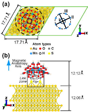
We consider a monolayer of Mn12 molecules adsorbed onto a Au(111) surface through thiol groups as shown in Fig. 1. Here we use the shortest chemical link between the Mn12 molecules and the gold surface. Although this link may seem too short to create stable Mn12 monolayers in experiments, it has advantages for theoretical studies. The link would considerably reduce computational cost by requiring a smaller unit cell without altering the physical and chemical properties of the system. If the molecules can be strongly coupled to the surface, this link would be a good candidate. Our DFT calculations show that the Mn12 molecular orbitals moderately broaden for the short link due to the interaction between the molecules and the surface. Electronic charge is transferred from the surface to the molecules and the total magnetic moment is also modified upon adsorption onto the surface. Our model and methods for studying a Mn12 monolayer on the gold surface are presented in Sec. II. The electronic structure and magnetic properties on the system are discussed in Sec. III. The conclusion follows.
II Model and methods
Spin-polarized DFT calculations are performed with plane waves as basis sets, within the Perdew-Burke-Ernzerhof (PBE) generalized-gradient approximation (GGA), Perdew et al. (1996) using the Vienna Ab-initio Simulation Package (VASP).Kresse and Furthmüller (1996a, b) Projector-augmented-wave (PAW) pseudopotentials Blöchl (1994a); Kresse and Furthmüller (1999) are employed to take into account spin-orbit interaction (SOI) that induces large magnetic anisotropy in a Mn12 molecule. Valence electrons considered in the PAW pseudopotentials for each atom are shown in Table 1. orbitals are treated as valence states for Au, and orbitals are used for Mn. Hard pseudopotentials are used for C and O. All DFT calculations in this study are performed self-consistently using VASP (unless stated otherwise) until the total energy converges down to 1.0 eV. To simulate a monolayer of Mn12 molecules on a Au(111) surface (Fig. 1), we consider a monoclinic unit cell of 17.7117.7134.00 Å3 in which a simplified form of a Mn12 molecule (explained specifically in Sec.II.B) is attached to a gold slab with six monolayers via thiol groups, and a vacuum layer of 10 Å is added above the Mn12 molecule. In this geometry the magnetic easy axis of the Mn12 molecules ( axis) is oriented normal to the surface. We first optimize a gold slab and a Mn12 molecule geometry, separately, and then combine them to create what we call the ‘whole structure’ illustrated in Fig. 1.
II.1 Gold slab
A DFT calculation is performed on bulk gold and convergence of the total energy is checked as a function of the number of -points, fast Fourier transform (FFT) mesh, an energy cutoff for plane waves, and a cutoff in augmentation charges. With an energy cutoff of 260 eV and a cutoff in augmentation charges of 357 eV, the calculated equilibrium lattice constant is 4.175 Å that differs from the experimental valueKhein et al. (1995) by 2.8%. In constructing the gold slab, in-plane separations among gold atoms are set to be 2.952 Å, obtained from the equilibrium geometry of bulk gold. With the in-plane separations fixed, the distance between monolayers is determined by atomic force relaxation until the magnitude of all force components is less than 0.01 eV/Å. To fully cover a Mn12 molecule on a Au(111) surface, a 661 real-space supercell (36 surface Au atoms per monolayer) is used. The surface area covered by the molecule is stressed by the dotted circle in Fig. 1(a). In addition, a gold slab should be thick enough to completely screen the Mn12 molecule including thiol groups with height of 12.12 Å. This condition is satisfied with six gold monolayers 12.06 Å high. In the whole structure we include the optimized geometry for a six-monolayer gold slab with 36 surface atoms per monolayer that contains a total of 216 gold atoms.
II.2 Isolated Mn12: geometries 1 and 2

To reduce computational cost, a simplified form of a Mn12 molecule, [Mn12O12(HCOO)16] (denoted geometry 1), is used in our study. The structure of geometry 1 is the same as what is shown in Fig.2(a) except that the S atoms are replaced by H. The simplified Mn12 differs from the synthesized Mn12 molecule in that the 16 acetate ligands were replaced by 16 formates (HCOO) and the four water molecules were removed because they may be lost via ligand-exchange during adsorption onto a surface.Steckel et al. (2004) Geometry 1 is placed in a unit cell of Å3, where the magnetic easy axis is along the axis. Then geometry 1 is relaxed with a fixed total magnetic moment of 20 (Bohr magneton) and an energy cutoff of 600 eV until the magnitude of all force components becomes less than 0.08 eV/Å. Using S4 symmetry of geometry 1, the twelve Mn ions are categorized into three classes marked as I, II, and III in Fig. 1(a). The four inner Mn ions (Mn4+) belong to symmetry class I, while the two sets of the four Mn ions (Mn3+) in the outer ring belong to symmetry classes II and III, respectively. The spin moments of the Mn4+ ions are antiparallel to those of the Mn3+ ions in the ground state. Our noncollinear calculation shows that a collinear spin approximation is good for geometry 1. The simplification made for the Mn12 molecule does not significantly change the electronic and magnetic properties of the molecule. The gap between the majority highest occupied molecular orbital (HOMO) and the majority lowest unoccupied molecular orbital (LUMO) is calculated to be 0.24 eV, while the minority HOMO-LUMO gap is 1.95 eV.
| Atomic | Valence Electron | Suggested Energy | Atomic Sphere |
|---|---|---|---|
| Species | Configuration | Cutoff Range (eV) | Radii (Å) |
| Au | 170-230 | 1.50 | |
| Mn | 202-270 | 1.32 | |
| O | 500-700 | 0.74 | |
| C | 500-700 | 0.86 | |
| S | 302-402 | 0.95 | |
| H | 200-250 | 0.37 |
| Atomic species | Initial magnetic moment | Change of magnetic moment upon adsorption |
|---|---|---|
| Mn (I) | 2.621,2.620,2.573,2.571 | +0.019,+0.021,+0.002,+0.001 |
| Mn (II) | 3.453,3.461,3.530,3.516 | +0.063,+0.060,+0.004,+0.004 |
| Mn (III) | 3.541,3.543,3.527,3.534 | +0.002,+0.003,+0.010,+0.010 |
| O closest to Mn and S | 0.011,0.011,0.028,0.027 | +0.015,+0.014,+0.036,+0.035 |
| O (total) | 0.328 | +0.105 |
| C closest to S | 0.007,0.007 | 0.008,0.008 |
| C (total) | 0.138 | 0.016 |
| S | 0.236, 0.235 | +0.237,+0.238 |
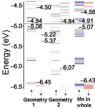
To attach the Mn12 molecules onto a gold surface, the H atoms in the two formates in geometry 1 are exchanged with surface-binding ligands, SH. Then the H atoms in SH are removed for the S atoms to be directly bonded to the gold surface. This determines the geometry 2, as shown in Fig. 2(a). The distance between the S atom and each bonding C atom is 1.88 Å, which was obtained from geometry optimization of Mn12-alkane-S-Au13. The Fermi level of the gold slab as well as molecular orbitals in its vicinity including HOMO and LUMO are depicted in Fig. 3 for geometries 1 and 2 and the whole structure. In geometry 2 the S atoms are highly reactive and their presence reduces both the majority and minority HOMO-LUMO gaps compared to geometry 1. Due to the lost H atoms, the HOMO and LUMO of geometry 2 are shifted downward compared to geometry 1 and the total magnetic moment of geometry 2 decreases to 18 . The calculated total energy of geometry 2 as a function of total magnetic moment is shown in Fig. 2(a). Magnetic moments for individual atoms are calculated over atom-centered spheres with radii given in Table I. See Table II. The S atoms bear substantial magnetic moments of 0.24 parallel to the inner Mn(I) ions. The magnetic moments of the Mn(I) and Mn(II) ions (denoted bold in Table II) connected to the S atoms via the O and C atoms are considerably smaller than those for geometry 1.
II.3 Whole structure: geometry 2 on Au(111)
Top and side views of the whole structure used in our DFT calculation are shown in Fig. 1. Each sulfur atom is bonded to the closest hollow (face-centered cubic) site on the gold slab which is the most favorable configuration. Attaching a sulfur atom at a bridge site requires a 0.30 eV higher energy than at a hollow site. This result agrees with a calculation on alkane thiols on a gold surface, for which a hollow site was favored by 0.40 eV.Yourdshahyan et al. (2001) A top site on a gold slab is the most expensive energetically. The distance from the sulfur atoms to the gold slab is optimized such that both sulfur atoms are as close as possible to hollow sites. The distances between the sulfur and the gold atoms range between 2.52 and 2.74 Å, where the longest bond is due to a slight mismatch of placing one of the sulfur atoms at the closest hollow site on the gold slab.
In the whole structure the closest distance between hydrogen atoms on periodic images of the Mn12 (geometry 2) is 3.35 Å. The large intermolecular separation prevents different Mn12 molecules from interacting with one another except for dipolar interactions. In the present study the dipolar interactions are not considered. The whole structure has a total of 304 atoms and 2886 valence electrons. Due to the presence of Mn atoms, an energy cutoff of 600 eV for plane waves and a cutoff in the augmentation charges of 800 eV are used. For the whole structure, we sample 221 -points, including the point. Notice that we used a 661 real-space supercell per gold monolayer. Thus, on the plane parallel to the gold surface, our -point sampling is equivalent to having (62)(62)=1212 -points in a 111 real-space gold cell. A further increase in the number of -points does not affect our results.
In a self-consistent calculation on the whole structure, the first-order Methfessel-Paxton scheme is used with the smearing parameter =6.0 meV. This choice of is necessary to resolve individual energy levels in projected density of states (PDOS) and to compute the MAB caused by the SOI in the Mn12 molecule. The total magnetic moment is set to 20 and the discussion in Sec. III suggests that 20 is the ground-state total magnetic moment for the whole structure. The combination of high energy cutoffs and a large number of valence electrons involved indicates the numerically expensive nature of the performed calculations so we do not further relax the whole structure. A comprehensive analysis of the forces exerted on the structure is provided. The average over absolute values of all of the , , and force components is (0.03,0.03,0.05) eV/Å with standard deviation of (0.08,0.07,0.08) eV/Å. Out of a total of 304 atoms, forces on only 25 atoms are greater than 0.15 eV/Å and the large forces occur near the sulfur atoms. The and components of the forces on the gold atoms bonded to the sulfur atoms are 0.60 eV/Å and the force components are 0.20 eV/Å with alternating signs. The forces on nearest neighbors to those gold atoms are 0.20 eV/Å along the and axes. The force on one of the sulfur atoms has components (0.57,0.29,0.13) eV/Å because of the mismatch of placing the sulfur atom at a hollow site of the gold slab. The forces onto the two carbon atoms bonded to the sulfur atoms are 0.39 eV/Å along the axis. The oxygen atoms bonded to those carbon atoms have force components that fall between 0.66 and 0.52 eV/Å. The Mn ions connected to the S via C and O atoms (two of the Mn(I) and two of the Mn(II) ions) have force components of 0.24 eV/Å. The analysis of the forces indicates that relaxation of the whole structure may possibly break the symmetries of the Mn(I) and Mn(II) ions, and could further modify its magnetic properties.
III Results and Discussion
The electronic structures of the six gold monolayers, geometries 1 and 2, and the whole structure are calculated and discussed using the PDOS onto particular orbitals of specific atoms. A comparison of the PDOS for the whole structure (Fig. 4) with those for geometry 2 (Fig. 5), computed under identical conditions, reveals that the molecule of geometry 2 is weakly coupled to the gold surface for the given link, and that the molecular orbitals broaden by at most an order of 0.1 eV. The Fermi level of the gold slab is well above the majority LUMO but below the minority LUMO of geometry 2 (Fig. 3). As a result, only electrons with majority spin can be transferred from the gold slab to the molecule. The ground-state total magnetic moment can also change upon adsorption on the surface due to strong bonds formed between the sulfur atoms and the gold slab. The amount of the charge transfer is quantified from two methods: (i) a one-dimensional electronic charge density difference between the whole structure and geometry 2, and (ii) a shift in the lowest-lying molecular orbital as a function of extra partial charges. The change in the total spin magnetic moment is obtained from a one-dimensional spin density difference. The effect of the charge transfer and spin magnetic moment change on the MAB is discussed from self-consistent SOI calculations.
III.1 Projected densities of states (PDOS)

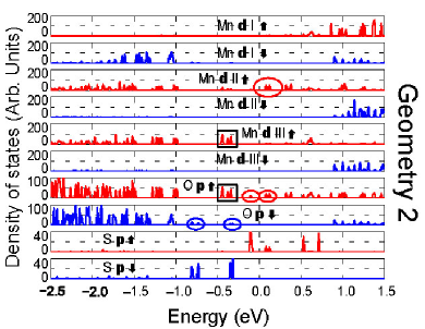
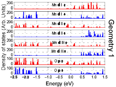
The PDOS shown in Figs. 4, 5 and 6 are generated with 100 data points/eV and smearing parameter =6 meV without the SOI, over atom-centered spheres with the radii given in Table 1. The horizontal scale in Figs. 5 and 6 is shifted by 0.34 eV and 3.5 meV, respectively, such that the zero in the horizontal scale corresponds to the midpoint of the HOMO and LUMO energies. The PDOS onto the gold and orbitals (not shown) indicate a large density of states within 0.5 eV below and above the gold Fermi level. To directly compare the PDOS for the whole structure with those for geometries 1 and 2, exactly the same parameter values are used for the three systems, such as an identical unit cell, -point sampling, energy cutoff, cutoff in the augmentation charges, PDOS sampling parameters, smearing parameter, and total energy convergence tolerance. For geometry 2 the HOMO and orbitals right below the HOMO are mostly from the Mn(III) ions, neighboring O anions, and S atoms, while the LUMO and orbitals right above the LUMO are from the Mn(II) ions, neighboring O anions, and the S atoms. As highlighted by ovals and squares in Fig. 5, the S orbitals are hybridized with the Mn and O orbitals. Within 0.5 eV below the midpoint of the HOMO and LUMO energies, the spin moments of the S atoms are antiparallel to those for the Mn(III) and O atoms. For geometry 1 the HOMO and orbitals right below the HOMO are mainly from the Mn(II) ions and O anions, while the LUMO and orbitals right above the LUMO are from the Mn(I) and Mn(III) ions and O anions (Fig. 6). These main differences of the PDOS between geometries 1 and 2 are linked to the difference of the total ground-state magnetic moment between them.
For the whole structure the PDOS (Fig. 4) onto the Mn and O orbitals noticeably differ from those for geometry 2 because of the difference in the total magnetic moment between them. Although the PDOS for the whole structure are similar to those for geometry 1, the peak heights in the former are reduced and the orbitals broaden compared to the latter. The broadening is of an order of 0.1 eV (Figs. 3, 4, and 6). The single-electron charging energy for geometry 2 is calculated from the energy difference between a neutral molecule and one with an extra-electron added. When one extra electron is added to geometry 2, the total ground-state magnetic moment increases to 19 . Considering the change in the total magnetic moment, we obtain the charging energy of 3.7 eV. This energy is one order of magnitude greater than the estimated broadening of the molecular orbitals so the molecule is weakly bonded to the surface.
III.2 Charge transfer
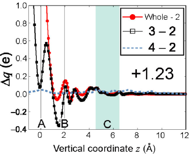
The charge transfer between the surface and the molecule of geometry 2 is computed from a one-dimensional electronic charge density difference between the whole structure and geometry 2 along the axis. The positive sign in the charge difference means an electronic charge is transferred from the gold surface to the molecule. The charge difference shown as the curve with filled circles in Fig.7, increases abruptly towards the sulfur atoms (vertical line A) due to the electronic contribution of the 36 gold surface atoms as well as the sulfur atoms. (Each gold atoms has 11 valence electrons.) The deep penetration of the charge of the gold atoms beyond the sulfur atoms makes it difficult to precisely calculate the amount of the charge transfer. Including the long tail of the charge of the gold surface atoms, a charge of 1.23 electrons (23.15 electrons) is transferred from the surface to the molecule when the integration is performed from the sulfur atoms, (the mid-distance between the first gold layer and sulfur atoms, ) to =12.00 Å (Fig. 7). It is found that the transferred charge is mostly localized in the sulfur and bonding carbon and oxygen atoms, while little charge is transferred to the Mn ions. A similar trend is shown for the charge density difference between geometry 2 and the structure where two H atoms are bonded to the S atoms [denoted geometry 3, Fig. 3(b)]. In this case, the charge difference obtained from integration from to Å, is 0.17 electrons. Notice that these two sets of the charge density difference match well above vertical line B in Fig. 7, indicating that the electronic environment around the molecular magnetic core is very similar in the whole structure and geometry 3. To further stress this point, we calculate the charge density difference between a neutral molecule with geometry 2 and the same molecule with 0.3 free electrons added. The extra free electrons are uniformly distributed over all atoms, as shown in Fig. 7.
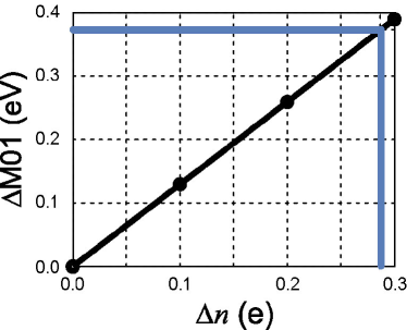
The charge difference is also calculated from the change of the lowest-lying occupied molecular orbital (MO1) of geometry 2 as a function of extra partial electrons added to the molecule, following the procedure described in Ref. Stadler and Jacobsen, 2006. As shown in Fig. 8, the MO1 changes linearly with extra partial charges. Here a correction due to the discontinuity in the derivative of the exchange-correlation potential with respect to electron density within DFT is not taken into account. The molecular orbitals of geometry 2 are modified upon adsorption onto the gold surface due to the interaction with the surface. Lying deeper in energy than the first occupied orbital of the gold slab, the MO1 is not hybridized with the gold surface. Thus, the shift of the MO1 in energy upon adsorption on the surface can be considered purely due to the charge transfer from the surface to the molecule, assuming that the Coulomb repulsion is small. The calculated shift of the MO1 between the whole structure and neutral geometry 2, 363 meV, leads to a charge transfer of 0.28 electrons, as depicted in Fig. 8.
III.3 Spin magnetic moment difference

The spin magnetic moment difference between the whole structure and geometry 2 is shown in Fig. 9. The increase in the total magnetic moment of the molecule upon adsorption amounts to 1.80 when the one-dimensional spin density difference is integrated from to =12 Å. As shown in Fig. 9 and Table 2, the major difference arises from the sulfur atoms due to the strong bonds to the gold surface, while the next considerable difference occurs at the O anions and Mn ions close to the surface. Since only electrons with majority spin can be transferred to the molecule, the Mn(I) and Mn(II) ions close to the surface have higher magnetic moments than those for geometry 2. The calculated difference of the spin magnetic moment corroborates the difference of the total ground-state magnetic moment between the whole structure and geometry 2. It is emphasized that this large change of the total magnetic moment is mainly caused by rearrangement of the magnetic moments of the S atoms and Mn ions due to the strong bonds to the gold surface, rather than by the charge transfer. Note that the total electronic charge must be conserved but not necessarily the total spin magnetic moment. A spin magnetic moment of 0.20 is obtained for the gold slab up to Å. As illustrated in Fig. 9, the magnetic moment difference between geometries 3 and 2, is remarkably similar to that between the whole structure and geometry 2. The two sets of the magnetic moment differences are, however, qualitatively dissimilar to the magnetic moment difference caused by 0.3 free electrons, shown by the dashed curve in Fig. 9. The extreme similarity in the one-dimensional charge and magnetic moment distributions in geometry 3 and the whole structure, as well as the moderate level broadening in the presence of gold, suggest that one estimate the MAB for the whole structure from a calculation on geometry 3.
III.4 Magnetic anisotropy barrier (MAB)
| Geometry 1 | Geometry 2 | Geometry 3, whole structure |
|---|---|---|
| 66.7 | 66.9 | 60.7 |
The magnetic anisotropy comes from Jahn-Teller distortion around the eight Mn3+ ions at the outer ring. It is known experimentally that for geometry 1 the second-order magnetic anisotropy contributes to the total MAB by 55 K and the fourth-order anisotropy by 10 K. Barra et al. (1997) With the total magnetic moment fixed, the MAB is computed from the change of the total energy upon a rotation of the spin quantization axis from the to the axis. The MAB calculated from a non self-consistent SOI calculation is 57.2 K for geometry 1, while the barrier from a self-consistent SOI calculation increases up to 66.7 K. The latter is more precise and may include higher-order magnetic anisotropy. This result agrees with the all-electron DFT-calculated barrier Pederson and Khana (1999) and experimental values.Barra et al. (1997); Hill et al. (1998) Henceforth we report only the MAB obtained self-consistently. The MAB with total magnetic moment of 18 is 66.9 K for geometry 2 so it remains the same as that for geometry 1. The transverse magnetic anisotropy is calculated to be 0.02 K, which is caused by the sulfur atoms. As discussed, geometry 3 is used to calculate the MAB for the whole structure. With the total magnetic moment of 20 , the calculated MAB for geometry 3 is 60.7 K that is 6 K lower than the MAB for geometries 1 and 2 (Table 3). Thus, a reasonable value for the whole structure would be also 60.7 K. The reduction in the barrier is due to the decrease in the single-ion anisotropy for the two Mn(II) ions close to the surface.
IV Conclusion
We have investigated, within DFT, the interaction between a single-molecule magnet Mn12 monolayer and a Au(111) surface through thiol bonds without long alkane chains. Despite a very short bond length between the sulfur-terminated Mn12 molecule and the gold slab, the broadening of the molecular orbitals was much less than the single-electron charging energy of the molecule. In the ground state the sulfur-terminated Mn12 molecule has a total magnetic moment of 18 , but its total magnetic moment increases to 20 upon adsorption onto the gold surface. The noticeable charge transfer from the surface to the Mn12 is attributed to (i) the relative position of the gold Fermi level to the LUMO and (ii) the long tail in the electronic cloud at the boundary of the gold surface. The self-consistent SOI calculation suggested a decrease in the MAB by 9% and a significant transverse magnetic anisotropy for the whole structure compared to the isolated Mn12. Although a relaxation of the whole structure may bring additional transverse magnetic anisotropy caused by minor symmetry breaking of the Mn ions close to the surface, it is unlikely that the molecules are completely collapsed upon adsorption. The analysis and results given in this study are not limited to the Mn12 molecules and may be applicable to systems where other types of magnetic molecules or SMMs are adsorbed onto nonmagnetic surfaces or bridged between nonmagnetic electrodes.
Acknowledgements.
M.C.A. and K.P. were supported by the Jeffress Memorial Trust Funds. Computational support was provided by the SGI Altix Linux Supercluster at the National Center for Supercomputing Applications under DMR060009N and by Virginia Tech Linux clusters and Advanced Research Computing.References
- Friedman et al. (1996) J. R. Friedman, M. P. Sarachik, J. Tejada, and R. Ziolo, Phys. Rev. Lett 76, 3830 (1996).
- Thomas et al. (1996) L. Thomas, F. Lionti, R. Ballou, D. Gatteschi, R. Sessoli, and B. Barbara, Nature 383, 145 (1996).
- Wernsdorfer and Sessoli (1999) W. Wernsdorfer and R. Sessoli, Science 284, 133 (1999).
- Ardavan et al. (2007) A. Ardavan, O. Rival, J. Morton, S. Blundell, A. Tyryshkin, G. Timco, and R. Winpenny, Phys. Rev. Lett. 98, 057201 (2007).
- Joachim et al. (2000) C. Joachim, J. K. Gimzewski, and A. Aviram, Nature 408, 541 (2000).
- Timm and Elste (2006) C. Timm and F. Elste, Phys. Rev. B 73, 235304 (2006).
- Leuenberger and Loss (2001) M. N. Leuenberger and D. Loss, Nature 410, 789 (2001).
- Steckel et al. (2004) J. S. Steckel, N. S. Persky, C. R. Martinez, C. L. Barnes, E. A. Fry, J. Kulkarni, J. D. Burgress, R. B. Pacheco, and S. L. Stoll, Nano Lett. 4, 399 (2004).
- Zobbi et al. (2005) L. Zobbi, M. Mannini, M. Pacchioni, G. Chastanet, D. Bonacchi, C. Zanardi, R. Biagi, U. del Pennino, D. Gatteschi, A. Cornia, and R. Sessoli, Chem. Comm. 12, 1640 (2005).
- Abdi et al. (2004) A. Nait Abdi, J.-P. Bucher, P. Rabu, O. Toulemonde, M. Drillon, and P. Gerbier, J. Appl. Phys. 95, 7345 (2004).
- Naitabdi et al. (2005) A. Naitabdi, J.-P. Bucher, P. Gerbier, P. Rabu, and M. Drillon, Adv. Mater. 17, 1612 (2005).
- Fleury et al. (2005) B. Fleury, L. Catala, V. Huc, C. David, W. Z. Zhong, P. Jegou, L. Baraton, S. Palacin, P.-A. Albouy, and T. Mallah, Chem. Commun. 15, 2020 (2005).
- Martínez et al. (2007) R. V. Martínez, F. García, R. García, E. Coronado, A. Forment-Aliaga, F. M. Romero, and S. Tatay, Adv. Mater. 19, 291 (2007).
- Salman et al. (2007) Z. Salman, K. H. Chow, R. I. Miller, A. Morello, T. J. Parolin, M. D. Hossain, T. A. Keeler, C. D. P. Levy, W. A. MacFarlane, G. D. Morris, H. Saadaoui, D. Wang, R. Sessoli, G. G. Condorelli, and R. F. Kiefl, Nano Lett. 7, 1551 (2007).
- Heersche et al. (2006) H. B. Heersche, Z. de Groot, J. A. Folk, H. S. J. van der Zant, C. Romeike, M. R. Wegewijs, L. Zobbi, D. Barreca, E. Tondello, and A. Cornia, Phys. Rev. Lett. 96, 206801 (2006).
- Jo et al. (2006) M.-H. Jo, J. E. Grose, K. Baheti, M. M. Deshmukh, J. J. Sokol, E. M. Rumberger, D. N. Hendrickson, J. R. Long, H. Park, and D. C. Ralph, Nano Lett. 6, 2014 (2006).
- Henderson et al. (2007) J. J. Henderson, C. M. Ramsey, E. del Barco, A. Mishra, and G. Christou, J. Appl. Phys. 101, 09E102 (2007).
- Barra et al. (1997) A. L. Barra, D. Gatteschi, and R. Sessoli, Phys. Rev. B 56, 8192 (1997).
- Voss et al. (2007a) S. Voss, M. Fonin, U. Rudiger, M. Burgert, and U. Groth, Appl. Phys. Lett. 90, 133104 (2007a).
- del Pennino et al. (2006) U. del Pennino, V. D. Renzi, R. Biagi, V. Corradini, L. Zobbi, A. Cornia, D. Gatteschi, F. Bondino, E. Magnano, M. Zangrando, M. Zacchigna, A. Lichteinstein, and D. W. Boukhvalov, Surf. Sci. 600, 4185 (2006).
- Voss et al. (2007b) S. Voss, M. Fonin, U. Rudiger, M. Burgert, U. Groth, and Y. S. Dedkov, Phys. Rev. B 75, 045102 (2007b).
- Kim and Kim (2004) G.-H. Kim and T.-S. Kim, Phys. Rev. Lett. 92, 137203 (2004).
- Elste and Timm (2006) F. Elste and C. Timm, Phys. Rev. B 73, 235305 (2006).
- Romeike et al. (2006a) C. Romeike, M. R. Wegewijs, and H. Schoeller, Phys. Rev. Lett. 96, 196805 (2006a).
- Romeike et al. (2006b) C. Romeike, M. R. Wegewijs, W. Hofstetter, and H. Schoeller, Phys. Rev. Lett. 97, 206601 (2006b).
- Leuenberger and Mucciolo (2006) M. N. Leuenberger and E. R. Mucciolo, Phys. Rev. Lett. 97, 126601 (2006).
- Perdew et al. (1996) J. P. Perdew, K. Burke, and M. Ernzerhof, Phys. Rev. Lett. 77, 3865 (1996).
- Kresse and Furthmüller (1996a) G. Kresse and J. Furthmüller, Phys. Rev. B 54, 11169 (1996a).
- Kresse and Furthmüller (1996b) G. Kresse and J. Furthmüller, Comp. Mat. Sci. 6, 15 (1996b).
- Blöchl (1994a) P. E. Blöchl, Phys. Rev. B 50, 17953 (1994a).
- Kresse and Furthmüller (1999) G. Kresse and J. Furthmüller, Phys. Rev. B 59, 1758 (1999).
- Khein et al. (1995) A. Khein, D. J. Singh, and C. J. Umrigar, Phys. Rev. B 51, 4105 (1995).
- Yourdshahyan et al. (2001) Y. Yourdshahyan, H. K. Zhang, and A. M. Rappe, Phys. Rev. B 63, 081405 (2001).
- Stadler and Jacobsen (2006) R. Stadler and K. W. Jacobsen, Phys. Rev. B 74, 161405(R) (2006).
- Pederson and Khana (1999) M. R. Pederson and S. N. Khana, Phys. Rev. B 60, 9566 (1999).
- Hill et al. (1998) S. Hill, J. A. A. J. Perenboom, N. S. Dalal, T. Hathaway, T. Stalcup, and J. S. Brooks, Phys. Rev. Lett. 80, 2453 (1998).