22institutetext: Arnold Sommerfeld Center for Theoretical Physics, Ludwig-Maximilians-Universität, Theresienstr. 37, D-80333 Munich, Germany
Optical polarizabilities of large molecules measured in near-field interferometry
Abstract
We discuss a novel application of matter wave interferometry to characterize the scalar optical polarizability of molecules at 532 nm. The interferometer presented here consists of two material absorptive gratings and one central optical phase grating. The interaction of the molecules with the standing light wave is determined by the optical dipole force and is therefore directly dependent on the molecular polarizability at the wavelength of the diffracting laser light. By comparing the observed matter-wave interference contrast with a theoretical model for several intensities of the standing light wave and molecular velocities we can infer the polarizability in this first proof-of-principle experiment for the fullerenes C60 and C70 and we find a good agreement with literature values.
1 Introduction
Matter-wave experiments with neutrons, electrons and atoms are well-established tools for the investigation of fundamental physical concepts Shull1969a (1, 2, 3, 4), as well as for innovative and practical measurement applications Rauch2000a (5, 6, 7, 8). Coherence experiments with complex molecules are still relatively young Arndt1999a (9). But also here interesting applications have been identified, such as for instance in measurements of molecular static polarizabilities Berninger2007a (10, 11).
Static polarizabilities and permanent dipole moments can be predicted by ab-initio and semi-classical methods Deachapunya2007a (11, 12) and they can be determined in molecular beam deflection experiments Bonin1997a (13, 14). All these methods may reach an accuracy of better than ten percent but they are also increasingly demanding with increasing particle mass and complexity.
Atomic Mach-Zehnder interferometry has achieved a precision of better than 1% for lithium Amini2003a (15) and better than 0.1% for sodium Ekstrom1995a (16), but this far-field arrangement is rather demanding in itself and it is strongly impeded for large molecules because it requires a collimation and a brilliance beyond those of existing molecular beams.
On the other hand, it has been shown, that near-field interferometry is well-suited for less intense sources of large objects Clauser1997a (17) and Talbot-Lau deflectometry was recently employed to measure the static polarizability of fullerenes Berninger2007a (10) as well as of porphyrins and porphyrin derivatives Deachapunya2007a (11).
All earlier interferometric polarizability experiments relied on the application of high static electric fields to shift the atomic Ekstrom1995a (16, 15) or molecular Berninger2007a (10) matter wave phase in proportion to the particle’s static polarizability.
Measurements of optical (AC) polarizabilities of clusters larger than diatomic molecules have not been available until a few years ago Ballard2000a (18). As of today only very few methods have been explored and exclusively demonstrated with fullerenes: Ballard et al. were the first to exploit the recoil imparted on a C60 beam when it crossed an intense standing light wave at 1064 nm Ballard2000a (18). Their detector was a position sensitive time-of-flight mass spectrometer which allowed to retrieve the polarizability at 1064 nm from a classical beam broadening.
In our present work we exploit near-field quantum diffraction in a Kapitza-Dirac-Talbot-Lau configuration Gerlich2007a (20) for retrieving the optical polarizability of both C70 and C60 from the evolution of the quantum fringe visibility as a function of the diffracting laser power. This scheme offers a higher throughput than in far-field diffraction experiments. Even in the pure quantum regime it is in principal scalable to masses beyond 10,000 amu and it can thus yield interesting information complementary to optical spectroscopy experiments.
2 Setup
Our new interferometer differs from an established earlier version Brezger2002a (21) in that it consists of two material gratings and one central optical phase grating Gerlich2007a (20). The first grating G1 prepares the necessary coherence of the only weakly collimated molecular beam. At the second grating G2, which is realized by a standing laser light wave at 532 nm, diffraction is based on the optical dipole potential
| (1) |
with the scalar optical polarizability and the electric field of the focused laser light wave . Near-field matter-wave interference, according to the Talbot effect, leads to self-imaging Clauser1994a (22, 23, 24) of the complex transmission function of G2 into a periodic molecular density distribution at the position of the third grating G3. The latter acts as a detector screen: shifting this mask across the periodic interference pattern and detecting the transmitted molecular flux then allows to reveal the molecular interference pattern.
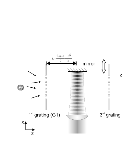
We designate our new setup as a Kapitza-Dirac-Talbot-Lau (KDTL) interferometer Gerlich2007a (20), as it combines the virtue of diffraction at standing light waves Martin1988a (25, 26, 27, 19) with the Talbot-Lau concept. The central optical grating becomes very important and useful for massive and highly polarizable particles as well as for small grating openings: For material gratings the influence of the van der Waals potential at the second grating would increase with and with shrinking distance between the molecules and the grating walls. In Grisenti1999a (28, 29) it has been shown that the particle-wall interaction adds a velocity and position dependent phase on the molecular wave function. In interferometry with material gratings this imposes a rather demanding experimental constraint, since high fringe contrasts can only be obtained in very narrow velocity bands, typically of the order of Brezger2002a (21, 20). This requirement can however be enormously alleviated by employing optical instead of material gratings. It turns out to be sufficient to have an optical diffraction grating in the center of the KDTL-interferometer alone: The first and third material gratings serve as absorptive masks for the preparation of coherence (G1) and the spatially resolved and parallel detection (G3) of the wide molecular beam. Additional phases which are imprinted onto the molecules by these structures, play no significant role for the formation of the interference pattern.
The SiNx material gratings have a period of d=266 nm, a thickness of 190 nm and an open fraction of f=0.42. The latter is the ratio between slit opening and grating period. The nanomasks were manufactured by T. Savas (MIT, Cambridge, USA) with a period homogeneity of better than d 1 Å across the entire width of the molecular beam. In the KDTLI setup G1 and G3 are separated by a distance of 210 mm as sketched in Fig. 1. The center of the standing light-wave is positioned with an uncertainty of less than m in the middle between these two masks. The light is derived from a green single-mode laser (Coherent Verdi 10 W at 532 nm), tightly focused by a cylindrical lens and back reflected from a planar mirror inside the vacuum chamber.
The fullerene beam is generated by an effusive source and passes the standing light wave in a distance of less than 300 m from the mirror surface, where the laser beam is already focused to and . The molecules are collimated by two slits to limit the angle of incidence onto the standing light-wave to degrees. This ensures that no molecule will average nodes and an anti-nodes of the light grating.
The fullerenes are detected behind the interferometer by either laser ionization, for C70, or electron impact ionization quadrupole mass spectrometry for C60. The spatial resolution of the detector is provided by the third grating which is mounted on a piezo-electric stage. It can be shifted with a repeatability of nm. The material gratings are mounted on rotation stages in order to allow alignment around the vertical axis and around the molecular beam axis with better than 300 rad precision. The velocity of the molecules is controlled by a gravitational velocity selection scheme Brezger2002a (21).
Interference in the Kapitza-Dirac-Talbot-Lau interferometer occurs at de Broglie wavelengths which fulfill the KDTL-condition
| (2) |
where m is an integer number. This condition, which is valid for weak laser intensities (, s. below) reveals that the interference maximum recurs with integer multiples of the Talbot period: , but shifted by half a period in comparison to the earlier Talbot-Lau interferometer Brezger2002a (21). For fullerenes at velocities between 100 m/s and 190 m/s our KDTLI-setup is operating between the fourth and the eighth Talbot diffraction order.
3 Theoretical model
The conservative interaction of the molecule with the electric field of the standing light-wave is described by the dipole potential of Eq. 1. The molecules thus acquire a position-dependent phase which enters the transmission function of G2:
| (3) |
with a maximal phase shift at the anti-nodes of
| (4) |
where is the real part of the optical polarizability at the laser wavelength and the light power Nairz2001a (19). We further include the possibility of photon absorption, which can lead to additional transverse momentum kicks imparted onto the molecules. The absorption process is governed by Poissonian statistics and the mean number of absorbed photons in an anti-node of the standing wave is
| (5) |
Here, is the absorption cross section at the laser wavelength, determined by the imaginary part of the optical polarizability at the laser frequency and is the light intensity. The expected interference fringe contrast at fixed molecule velocity is then given by Gerlich2007a (20)
| (6) |
where
| (7) |
accounts for the coherent interaction and
| (8) |
for the incoherent scattering of photons. Here is the distance between the gratings and is the Bessel function of the second kind.
4 Polarizability measurements
As can be seen from the equations above, the molecular optical scalar polarizability enters directly the interference visibility of the KDTL-interferometer, through the maximum phase shift . We can therefore exploit the KDTLI to determine when the resonant absorption cross section is known from separate experiments, such as gas-phase spectroscopy. In the following we compare the experimentally observed dependence of the interference contrast on the varying laser power and on the molecular velocity with the theoretical model from section 3.
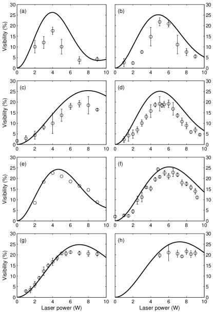
The interference patterns of C70 are recorded for eight different velocity distributions and for up to twenty different laser powers . For each sinusoidal interference curve we extract the experimental fringe visibility and plot it versus the diffracting laser power, as shown in Fig. 2. We then fit the resulting curves with equation (6), using the polarizability as a single free parameter, common for all laser powers and velocities. Given the value for the optical absorption cross section Coheur1996a (30, 31) cm-2 and including the experimentally determined velocity distributions in our theoretical model we then determine the scalar optical polarizability to be Å3.
This value is consistent with earlier results obtained from the dielectric response of thin fullerene films Eklund1995a (32, 33). It is also in good agreement with measurements of the gas-phase static polarizability which has been determined to be Å3 using Stark deflectometry Compagnon2001c (34) and Å3 by Talbot-Lau deflectometry Berninger2007a (10). The optical polarizability is expected to be higher than the static value since the incident light approaches (still from far away) allowed optical transitions at 532 nm. A comparison of our work with literature values for fullerene polarizabilities at 532 nm is shown in Table 1.
| thin films Eklund1995a (32) | EELS Sohmen1992a (33) | theory Ruud2001a (35) | this work | |
|---|---|---|---|---|
| C60 | 90 Å3 | 98.2 Å3 | 80.6 | 90(11)Å3 |
| C70 | 118.4 Å3 | 122.6 Å3 | - | 117(14)Å3 |
The error bars in our experiment have various different contributions: Firstly, the absolute calibration of our present optical power meter is good to within 10%. This is a systematic uncertainty in the power measurement, but the reproducibility and linearity in the reading are better than 5%. Secondly, the vertical waist of the laser beam enters linearly in the available intensity. In our present measurements it could been measured with an accuracy of 5%. In contrast to that, the horizontal laser waist (20m) can only be measured with an estimated accuracy of 20%, but its uncertainty cancels out in first order, since a larger waist is associated with a lower intensity but also with a longer transition time for the molecules. Thirdly, the knowledge of the optical absorption cross section is relevant for the numerical fit of the data. However it enters very weakly: even an uncertainty of 50% in results only in a variation of the fit value for the polarizability. Fourthly, there is a statistical error, as can be seen from the scatter of the data points. Taking a ’worst case scenario’ by separately fitting the upper and the lower envelope of all error bars in the data distribution, we see a maximum uncertainty of 2.3 Å3. Systematic deviations of the interferogram from an ideal fringe contrast, which can be caused by day-to-day variations of the laboratory noise background, enter very weakly into the fit value. All experimental uncertainties mentioned above contribute independently and sum up to a total uncertainty of 12%.
Most parameters can clearly be improved in future experiments: With an improved detection efficiency the width of the velocity distribution can probably still be reduced by an order of magnitude. The measurement of the laser power and waist may still be improved by a factor of three using commercially available sensors.
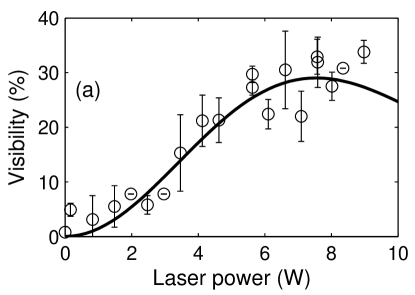
In Fig. 3 we show the power dependence of the fringe contrast of for a mean molecular velocity of 153 m/s and a standard deviation of . The larger error bars here are caused by the lower detection efficiency of in comparison to . We again use equation 6 to fit the experimental data points and evaluate, for a given absorption cross section of cm2 Coheur1996a (30, 36), the dynamic polarizability of C60 at 532 nm to be Å3. This value is in good agreement with previous measurements, as shown in Table 1 and also consistent with the static polarizability values which were determined by Stark-deflectometry (Å3 Antoine1999a (14)) and by interferometric Talbot-Lau deflectometry (Å3 Berninger2007a (10)).
In conclusion we have used a Kapitza-Dirac-Talbot-Lau interferometer to determine the scalar optical polarizability of both Fullerenes C60 and C70. Our method can be extended to all volatile molecules that may be subjected to KDTL-interferometry. In the present setup this can cover a wide class of effusive beams in principle with molecular masses up to 10,000 amu.
Combined with an independent evaluation of optical absorption cross sections the new technique can be an interesting complement to existing methods Ballard2000a (18, 19, 13) and it will provide new data for a large set of molecules as an experimental benchmark for new computational molecular models.
Acknowledgements
This work has been supported by the Austrian Science Foundation (FWF), within the SFB projects F1505 and F1512 and START Y177. K.H. acknowledges support within the Emmy Noether program by the German Science Foundation DFG.
References
- (1) C. G. Shull, Phys. Rev. 179, 752 (1969).
- (2) G. Moellenstedt and C. Z. Joensson, Z. Phys. 155, 472 (1959).
- (3) O. Carnal and J. Mlynek, Phys. Rev. Lett. 66, 2689 (1991).
- (4) D. W. Keith, C. R. Ekstrom, Q. A. Turchette, and D. E. Pritchard, Phys. Rev. Lett. 66, 2693 (1991).
- (5) H. Rauch and A. Werner, Neutron Interferometry: Lessons in Experimental Quantum Mechanics (Oxford Univ. Press, Oxford 2000).
- (6) D. L. Price, Neutron Scattering, Part B, 23 Experimental Methods in the Physical Sciences (Academic Press Inc., New York 1996).
- (7) A. Tonomura, Reviews of Modern Physics 59, 639 (1987).
- (8) A. D. Cronin, J. Schmiedmayer, and D. E. Pritchard, Rev. Mod. Phys. (2007).
- (9) M. Arndt, O. Nairz, J. Voss-Andreae, C. Keller, G. V. der Zouw, and A. Zeilinger, Nature 401, 680 (1999).
- (10) M. Berninger, A. Stéfanov, S. Deachapunya, and M. Arndt, Phys. Rev. A (2007).
- (11) S. Deachapunya, P. J. Fagan, A. G. Major, E. Reiger, H. Ritsch, A. Stefanov, H. Ulbricht, and M. Arndt, http://arxiv.org/abs/0708.1449 (2007).
- (12) M. Frisch, G. Trucks, H. Schlegel, G. Scuseria, M. Robb, J. Cheeseman, J. Montgomery, Jr., T. Vreven, K. Kudin, et al., Gaussian 03W, Version 6.0 (Gaussian Inc., Pittsburgh, PA, 2003).
- (13) K. Bonin and V. Kresin, Electric-Dipole Polarizabilities of Atoms, Molecules and Clusters (World Scientific, Singapore 1997), ISBN 981-02-2493-1.
- (14) R. Antoine, P. Dugourd, D. Rayane, E. Benichou, M. Broyer, F. Chandezon, and C. Guet, J. Chem. Phys. 110, 9771 (1999).
- (15) J. M. Amini and H. Gould, Phys. Rev. Lett. 91, 153001 (2003).
- (16) C. Ekstrom, J. Schmiedmayer, M. Chapman, T. Hammond, and D. Pritchard, Phys. Rev. A 51, 3883 (1995).
- (17) J. Clauser, in Experimental Metaphysics, edited by R. Cohen, M. Horne, and J. Stachel (Kluwer Academic, Dordrecht 1997).
- (18) A. Ballard, K. Bonin, and J. Louderback, J. Chem. Phys. 114, 5732 (2000).
- (19) O. Nairz, B. Brezger, M. Arndt, and A. Zeilinger, Phys. Rev. Lett. 87, 160401 (2001).
- (20) S. Gerlich, L. Hackermüller, K. Hornberger, A. Stibor, H. Ulbricht, M. Gring, F. Goldfarb, T. Savas, M. Müri, M. Mayor, and M. Arndt, Nature Physics, doi:10.1038/nphys701 (2007).
- (21) B. Brezger, L. Hackermüller, S. Uttenthaler, J. Petschinka, M. Arndt, and A. Zeilinger, Phys. Rev. Lett. 88, 100404 (2002).
- (22) J. F. Clauser and S. Li, Phys. Rev. A 49, R2213 (1994).
- (23) B. Dubetsky and P. R. Berman, in Atom Interferometry, edited by P. R. Berman (Academic Press, San Diego 1997).
- (24) K. Hornberger, J. E. Sipe, and M. Arndt, Phys. Rev. A 70, 53608 (2004).
- (25) P. J. Martin, B. G. Oldaker, A. H. Miklich, and D. E. Pritchard, Phys. Rev. Lett. 60, 515 (1988).
- (26) P. L. Kapitza and P. A. M. Dirac, Proc. Camb. Philos. Soc. 29, 297 (1933).
- (27) D. L. Freimund, K. Aflatooni, and H. Batelaan, Nature 413, 142 (2001). Ph.D. thesis, University of Nebraska (2003).
- (28) R. E. Grisenti, W. Schöllkopf, J. P. Toennies, G. C. Hegerfeldt, and T. Köhler, Phys. Rev. Lett. 83, 1755 (1999).
- (29) R. Brühl, P. Fouquet, R. E. Grisenti, J. P. Toennies, G. C. Hegerfeldt, T. Köhler, M. Stoll, and C. Walter, Europhys. Lett. 59, 357 (2002).
- (30) P. F. Coheur, M. Carleer, and R. Colin, J. Phys. B: At. Mol. Opt. Phys. 29, 4987 (1996).
- (31) K. Hornberger, L. Hackermüller, and M. Arndt, Physical Review A 71, 023601 (2005).
- (32) P. Eklund, A. Rao, Y. Wang, P. Zhou, K. Wang, J. Holden, M. Dresselhaus, and G. Dresselhaus, Thin Solid films 257, 211 (1995).
- (33) E. Sohmen, J. Fink, and W. Krätschmer, Z. Phys. B 86, 87 (1992).
- (34) I. Compagnon, R. Antoine, M. Broyer, P. Dugourd, J. Lerme, and D. Rayane, Phys. Rev. A 64, 025201 (2001).
- (35) K. Ruud, D. Jonsson, and P. R. Taylor, J. Chem. Phys. 114, 4331 (2001).
- (36) C. Ferrante, R. Signorini, A. Feis, and R. Bozio, Photochem. Photobiol. Sci. 2, 801 (2003).