Voice Service Support in Mobile Ad Hoc Networks ††thanks: This work was supported by the U.S. National Science Foundation under Grants ANI-03-38807 and CNS-06-25637, and a Postdoctoral Fellowship and a research grant from the Natural Science and Engineering Research Council (NSERC) of Canada.
Abstract
Mobile ad hoc networks are expected to support voice traffic. The requirement for small delay and jitter of voice traffic poses a significant challenge for medium access control (MAC) in such networks. User mobility makes it more complex due to the associated dynamic path attenuation. In this paper, a MAC scheme for mobile ad hoc networks supporting voice traffic is proposed. With the aid of a low-power probe prior to DATA transmissions, resource reservation is achieved in a distributed manner, thus leading to small delay and jitter. The proposed scheme can automatically adapt to dynamic path attenuation in a mobile environment. Simulation results demonstrate the effectiveness of the proposed scheme.
Keywords – medium access control, code-division multiple access, mobile ad hoc networks.
I Introduction
Mobile ad hoc networks are expected to support multimedia services such as voice and video with quality-of-service (QoS) requirements. This task is challenging because there is no network central controller in such networks. User mobility makes the case even worse because of the time-varying network topology and propagation loss between any two nodes. QoS support in mobile ad hoc networks includes two directions: via routing at the network layer or via medium access control (MAC) scheme at the link layer. The function of routing is to search for a network path (i.e., a route) from a traffic source node to its destination node, and to react (e.g., select a new route) to possible route failures and/or network congestion. On the other hand, the function of MAC is to coordinate the channel access in an orderly manner among the mobile nodes such that efficiency can be achieved. Here, we focus primarily on the MAC in a mobile ad hoc network supporting voice traffic. In such a network, a MAC scheme should be: 1) distributed (because of the scalability requirement); 2) tolerant to the hidden terminal problem; 3) ensuring of small delay/jitter (due to the real-time nature of voice traffic); and 4) adaptive to user mobility. In this paper, we propose an effective MAC scheme with the above desired features. The MAC scheme is fully distributed, thus scaling well to a large network. The hidden terminal problem does not exist in our scheme. Radio resource requirements are met by resource reservation, thus achieving small delay and jitter. Our scheme can also adapt to user mobility to a certain extent.
II Related Work and Discussion
The most popular MAC schemes for ad hoc networks are carrier-sense multiple access (CSMA) and its variants, and busy-tone based schemes. The CSMA schemes are inherently distributed. However, they suffer from the hidden terminal problem. Also, the schemes are based on an ideal assumption, i.e., that there is an interference range for each transmitter. As long as a target receiver is outside the interference range of an interferer, it is assumed that the interferer does not generate any interference to the target receiver. However, in reality, the aggregate interference from a number of far-away interferers (each with a distance to the target receiver larger than the interference range) may corrupt the reception at the target receiver. On the other hand, one motivation of busy-tone based schemes [1] is to better solve the hidden terminal problem. With the aid of a receive busy-tone transmitted by a target receiver, the hidden terminals near the target receiver can be notified not to transmit. However, the hidden terminal problem is not eliminated. For instance, collisions of request-to-send (RTS) frames can still happen due to the hidden terminal problem [2]. It is also challenging to determine the busy-tone coverage. Traditionally the busy-tone coverage is set to be the same as the interference range. However, similar to the case in CSMA, the aggregate interference from multiple interferers outside the coverage of a busy-tone (sent by a target receiver) can corrupt the reception at the target receiver. In a mobile environment, the multipath fading can also cause the busy-tone coverage to vary with time. This can severely degrade the system performance because a strong interferer may not be notified by the busy-tone due to instantaneous deep fading of the busy-tone channel.
The contention-based nature of CSMA schemes and busy-tone based schemes makes it very difficult to bound the delay and jitter to small values for voice traffic. This observation implies that we should instead resort to reservation of channel resources. Resource reservation can avoid contentions, and voice traffic can be transmitted continuously on the reserved channel, thus making the transmission delay and jitter bounded. Here we consider a code-division multiple access (CDMA)-based mobile ad hoc network, where the air interface supports multiple simultaneous transmissions in a neighborhood. In our previous work [3], we have proposed a MAC scheme for a CDMA-based wireless mesh backbone, referred to as MESH scheme here. Before DATA transmissions, each potential sender first transmits a low-power probe to the network. Upon reception of the probe, each active receiver estimates a potential interference increase due to the potential sender’s DATA transmission. The active receiver transmits a busy-tone signal in a separate busy-tone channel to notify the potential sender if the potential interference increase is intolerable. If the potential sender does not detect a busy-tone, it successfully reserves a code channel. However, targeted at a wireless mesh backbone with fixed topology, the MESH scheme is not effective or efficient in a mobile ad hoc network for the following reasons: 1) The power allocation strategy in MESH largely depends on the fixed network topology, and thus it is not applicable to a mobile network; 2) A single-frequency busy-tone channel is used in MESH. The busy-tone transmission can be affected significantly by fading and/or shadowing in a mobile environment. The coverage of the busy-tone fluctuates with time, thus severely degrading the system performance.
Based on the similar approach of “probing” in the MESH scheme, in the following we propose a MAC scheme for a mobile ad hoc network supporting voice traffic.
III The Proposed MAC Scheme
Consider a mobile ad hoc network with a number, , of mobile nodes. At the MAC layer, a source node can communicate with one or more of its neighbors, with a separate queue for each destination node. Each node is assigned a unique transmitting code and a unique receiving code [4]. Constant rate voice traffic is supported. The network topology changes as the mobile nodes move.
Each voice link requires a minimum transmission rate (e.g., voice packet generation rate from the codec) so that its delay and jitter can be kept at a very low level. To keep the transmission accuracy of the voice link, a signal to interference plus noise ratio (SINR) threshold is required for each link, i.e., for the link from sender to receiver , the following inequality should hold: , where is the spreading gain, is the transmit power, is the path gain from node to node , is the interference (received at node ) from other links, is the background noise power at node , and is the required SINR threshold for accurate information transmission.
Unlike the situation for the MESH scheme, all the transmissions are within a frequency band, using CDMA technology. A RAKE receiver can collect signal energy from different paths. Hence, we assume that there is no fast (multipath) fading, and the transmit power is attenuated only due to path loss with exponent and shadowing. A node cannot transmit and receive at the same time, since each node’s transmission and reception are within the same frequency band.
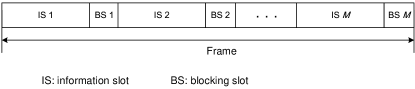
In the time domain, we use a time frame structure as shown in Fig. 1. Time is partitioned into fixed-length frames. In each frame, there are information slots (ISs), each followed by a short blocking slot (BS). The ISs are used for information (i.e., DATA and ACK) and probe transmissions, while the BSs are used for the transmission of blocking messages (to be discussed).
In a mobile ad hoc network, it is difficult to estimate the path attenuation in advance from a sender to a receiver due to user mobility. Therefore, the popular linear power allocation [5] is not adopted. Rather, we consider a common power allocation strategy, where each traffic source node uses a constant power to transmit its DATA frames to its destination, and the traffic destination uses the same power level to feed back ACKs.
III-A Multiple Access Procedure
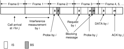
The multiple access capability of the network is based on resource reservation. Consider the case of a new call arrival at source node at time frame 0 to its destination node . The multiple access procedure is illustrated in Fig. 2.
III-A1 Selection of DATA IS
Node first selects an IS for DATA transmission, referred to as its DATA IS. The ISs at which the destination node is sending traffic should be skipped, because node cannot send and receive at the same time at the same band. At frame 1, node measures its experienced interference, and monitors the transmitting code of node . Among the ISs over which node ’s transmitting code is not detected, node selects one with the minimum interference level, say IS , as its DATA IS.
III-A2 Transmissions of Probe and Blocking Message
Prior to DATA transmission at the selected DATA IS, node should make sure its DATA transmission does not corrupt any existing reception at any active receiver111Here an active receiver can be an existing traffic destination node for DATA reception, or an existing traffic source node for ACK reception. at the IS. To achieve this goal, node first sends a low-power test signal into the network. Specifically, at IS of frame 2, node sends a probe spread by a common probe code with a large spreading gain, and with transmit power level (). No bit information is carried in the probe. With the low power, the probe is very likely not to corrupt any existing reception at the IS. Although the probe is sent with low power, we assume that it can be received by active receivers at the IS because of the large spreading gain.
At IS , an active receiver, say node , first measures the received probe power level denoted by and its own interference level due to other existing transmissions. It estimates the potential interference increase due to DATA transmission of the probe sender as , and determines whether the potential interference increase can corrupt its own reception. If so, it sends a blocking message at BS . The blocking message is spread by a common blocking code. No bit information is carried by the blocking message. The power allocation for the blocking message will be discussed in Section III-B.
At BS , node monitors the blocking code. If the detected blocking message power is above a threshold , it gives up IS for DATA transmission and tries another IS until no blocking message is detected.
III-A3 Selection of ACK IS
If no blocking message is detected, node sends a request message to its destination node , at IS in frame 3 spread by node ’s receiving code, and sends its first DATA frame at slot in frame 4 spread by node ’s transmitting code, both with power .
Upon receiving the request message, node selects an IS for its ACK, referred to as ACK IS. Generally it is desired that, at the ACK IS, the interference experienced by node is small so that the ACK can be received correctly. So in the request message, node indicates (among the ISs except IS ) the IS with minimal experienced interference, say IS . After node receives correctly the request, it sends an probe at IS in frame 3222The probe is sent at IS in frame 3 when , or in frame 4 when . For simplicity of presentation, we use the former case as an example in this paper. in the same manner as node sending a probe for DATA IS. If no blocking message is detected at BS , node sends an ACK at IS in frame 4 for the DATA frame received333Since the request message and DATA are sent in the same way from node , DATA can also be received correctly if the request can be delivered successfully. in frame 4.
If node does not receive an ACK at IS of frame 4, it selects another DATA IS, and repeats the above procedure with a maximum number of attempts. If an ACK is received, it proceeds to next step.
III-A4 Continuous Transmissions at Reserved DATA and ACK ISs
At subsequent time frames from frame 5, node transmits its DATA frames spread by its transmitting code at IS , and node transmits the ACKs spread by its transmitting code at IS , until the completion of the call. It can be seen that call-level resource reservation is performed. Upon the call completion, no link termination procedure is necessary, because our scheme is based on real-time interference measurement, and other active receivers can measure the interference level reduction when the target link stops using the reserved resource.
III-B Power Allocation for the Blocking Message
If an active receiver at an IS is to send a blocking message in response to a probe from a potential sender444Here a potential sender can be a traffic source node for DATA transmission or a traffic destination node for ACK transmission., the transmit power of the blocking message should be designed carefully so that the potential sender can be notified. Unlike the MESH scheme, other active receivers at the IS do not need to hear the blocking message. As the blocking message is sent in the same frequency band as DATA frames, here we use a different method (from that in the MESH scheme) for an active receiver to determine its blocking message power based on the measured probe power. The objective is to ensure that the potential sender can detect a blocking message with power above threshold .
At an IS, it is possible that one or more potential senders may send probes for resource reservation. Since the resource reservation is performed at the call level, it is reasonable to assume that at an IS there are at most two potential probe senders in a neighborhood. We also assume channel reciprocity in terms of shadowing effect. Consider the case in which an active receiver, say node , detects the probe power level , and wants to send a blocking message. Node sends a blocking message with transmit power
| (1) |
where is the interference margin [6] of node , defined as the maximum extra interference that can be tolerated by node .
We first consider the scenario in which only one potential sender, node , sends a probe at an IS. The path gain from node to node is From (1) we have
| (2) |
Due to the channel reciprocity, , we have Then the received blocking message power at the potential sender is , which is greater than the detection threshold . So the potential sender is notified to give up the IS.
Next, we consider the scenario in which two potential senders, node and node , send probes at an IS. As a common probe code is used, and no bit information is carried by a probe, node can collect energy from both probes via an RAKE receiver. The total received probe power at node is also denoted by . Suppose node wants to send a blocking message. Without loss of generality, assume the path gain from node to is larger than that from to , i.e., . We have
| (3) |
When node sends a blocking message with power given by (1), the received blocking message power at node is
| (4) |
So node will be notified to give up the IS.
In the following, we prove that, if node ’s potential information (i.e., DATA or ACK) transmission generates extra interference that is intolerable at node , node ’s blocking message with power given by (1) can reach node with a power level above the threshold .
Proof:
If node ’s information transmission can corrupt node ’s reception, this means We have When node sends a blocking message with power given by (1), the received blocking message power at node is
| (5) |
As node detects blocking message power above the threshold, it gives up the IS. ∎
III-C Impact of User Mobility and Solutions
The impact of user mobility on each active link at the MAC layer is two-fold. One is due to the time-varying path attenuation of the desired signal, and the other is due to the varying interference level. The path attenuation consists of three components: path loss, shadowing, and fast (multipath) fading. Fast fading can be addressed by the RAKE receiver that collects signal energy from different paths. The time-varying path loss, shadowing, and interference level make the SINR of each link fluctuate with time. Generally our scheme can automatically adapt to the varying SINR of each link, because the receiver makes real-time measurement of its desired signal and interference levels. However, it is possible that the SINR of some ongoing links at an IS cannot remain above the threshold (a condition referred to as a link failure) because of the fluctuations. Although a new route searched by the routing scheme can help to solve the problem, it is desirable to deal with the problem at the MAC layer first before resorting to the routing scheme, considering the overhead and time needed for a new route search, and the duration needed to set up a new route.
To address the problem, for each active link, the traffic destination node indicates in its ACK two candidate DATA ISs at which the destination node experiences the minimum interference and does not transmit. The destination node also indicates a detected link failure (if any) in the ACK. If the traffic source node (say node ) does not receive correctly the ACK from its destination (say node ), this means a link failure happens because the ACK is corrupted555If an expected DATA frame is not received, the traffic destination node responds with a NACK. For presentation simplicity, we use “ACK” to represent both ACK and NACK in this paper.. As node does not have the information of whether the DATA transmission is corrupted or not, we let the link be re-established at a new DATA IS and a new ACK IS. The main difference from the establishment procedure given in Section III-A is as follows. Node sends two probes at the two candidate DATA ISs indicated in the previous ACK. At each candidate IS, a request is sent if no blocking message is detected. The request also indicates two candidate ACK ISs at which node experiences the minimum interference and does not transmit. If at least one request is received at node (which means a new DATA IS is established), node sends two probes at the candidate ACK ISs. If at least one probe at a candidate ACK IS is not blocked by active receivers at that IS, a new ACK IS is established. If either a new DATA IS or a new ACK IS cannot be established, the call is dropped.
On the other hand, if node successfully receives an ACK which indicates that a failure of DATA transmission happens, a similar procedure is executed, except that only the establishment of a new DATA IS is needed.
Generally, if the link failure is due to large interference, it is likely that the call can be established successfully in other DATA and/or ACK ISs at which nodes generate large interference are not active. However, if the link failure is due to a large path loss of the desired signal (e.g., the traffic source and destination are separated by a large distance) or due to shadowing of the desired signal (e.g., the path between the traffic source and destination is blocked by a tall building), it is very likely that the link quality of the target call at other ISs is not good enough either, and thus the call will be dropped. In this case, a new route should be selected by the routing scheme.
The proposed MAC scheme has the desired features discussed in Section I. The scheme is performed in a distributed manner at the mobile nodes, thus scalable to large networks. The hidden terminal problem does not exist, since each active receiver makes an admission decision on a new call based on real-time measurement of its own desired signal and interference levels. The reservation nature of our scheme can guarantee small delay and jitter for voice traffic as long as the minimum required rate can be met. Our scheme can adapt automatically to user mobility to a certain extent, also benefiting from the fact that each active receiver makes real-time measurement of desired signal and interference levels. In addition, the “ideal assumption” required by CSMA and busy-tone based schemes (as discussed in Section II) is unnecessary for our scheme. Furthermore, although the blocking message has similar functionality to the busy-tone in the busy-tone based scheme, our scheme does not have the problem of different channel gains in separate busy-tone frequency band and DATA frequency band, because the blocking message and DATA are sent in the same band.
IV Performance Evaluation
We run computer simulations to evaluate the performance of the proposed MAC scheme. Since MAC mainly deals with the transmission from a node to its neighbors, only one-hop transmission is considered here. Consider an ad hoc network consisting of nodes, with voice source nodes and voice destination nodes. The source nodes are randomly distributed in a 1000 meter 1000 meter square, each associated with a destination node. All the source nodes are fixed, and all the destination nodes move with a velocity and a randomly selected direction. In order to maintain a satisfactory SINR, a destination node is assumed to move within a radius of 150 m of the associated source node666Routing may be involved when a destination node moves beyond this distance, a situation which is beyond the scope of this work.. Each time frame has a fixed duration of 20 ms, and is further divided into 8 ISs and 8 BSs. The spreading gain is 32 for DATA and ACKs, and 3200 for the probe. The path loss attenuation exponent is 2.4, and the shadowing is modeled by the first-order autoregressive process given in [7]. Voice call inter-arrival time at each source node is exponentially distributed with mean value 48 seconds, and the duration of a call is exponentially distributed with mean value 30 seconds. When a call is active, one DATA frame is generated over each time frame. The SINR requirement is 10 dB.
In the simulations, the number of nodes varies from 20 to 100, and the destination node velocity varies from 0 to 20 km/hour (kph). We first verify our assumption in Section III-B that the probability of more than two probe senders at an IS is negligible. Among the ISs with one or more probe senders, Table I lists the percentage of ISs that have one probe sender, two probe senders, and more than two probe senders, respectively. No more than two probes are observed at an IS, thus validating our assumption.
| Number () of nodes | 20 | 40 | 60 | 80 | 100 | |
|---|---|---|---|---|---|---|
| 1 probe | 1.000 | 1.000 | 0.998 | 0.996 | 0.997 | |
| 2 probes | 0 | 0 | 0.002 | 0.004 | 0.003 | |
| kph | probes | 0 | 0 | 0 | 0 | 0 |
| 1 probe | 1.000 | 0.996 | 1.000 | 0.995 | 0.996 | |
| 2 probes | 0 | 0.004 | 0 | 0.005 | 0.004 | |
| kph | probes | 0 | 0 | 0 | 0 | 0 |
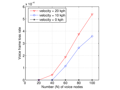
For an ongoing voice call, if its SINR requirement is not satisfied, it tries to switch from one IS to another. Some DATA frames will be lost during the switching due to the switching processing time, and if the switching is not successful, call dropping occurs. Fig. 3 shows the DATA frame loss rate with different and values. A larger value of and/or tends to increase the frequency of switching among the ISs, thus increasing the frame loss rate. It can also be seen that all the frame loss rates are bounded by 0.05%, which is well within acceptable range for voice. It is also observed that the call dropping rate is bounded by 1.2%, which happens when and kph. So our scheme can keep the frame loss rate and call dropping rate at a low level.
V Conclusions and Discussions
It is challenging to support voice traffic over a mobile ad hoc network due to the delay-sensitive nature of such traffic and due to user mobility. In this paper we have proposed a MAC scheme to support voice traffic by the resource reservation mechanism. User mobility is addressed by real-time signal and interference measurements at the receivers. This study should provide helpful insight to the development and deployment of mobile ad hoc networks supporting multimedia services.
Currently constant rate voice traffic has been considered in this research. However, voice traffic is characterized by an on-off nature, and no information packets are generated at an off state. When an on voice flow becomes off, other active receivers measure less interference. If subsequently one or more new calls are admitted at the serving ISs of the off voice flow, and later the off voice flow switches to the on state, it is likely that some active receivers experience more interference than what they can tolerate, thus leading to link corruption. To address this problem, when a voice flow becomes off, its source and destination nodes continuously send (on the respective serving IS) a probe (with a different code from that used in Section III-A) with a low power and a large spreading gain. Through the received probe power, an active receiver at the IS can estimate the potential interference level which will be generated if the off voice flow becomes on again. The potential interference is counted in the active receiver’s current interference level. We call this method 100-percent reservation, without a multiplexing gain. Research on statistical multiplexing of voice traffic within this scheme is currently underway.
References
- [1] Z. J. Haas and J. Deng, “Dual busy tone multiple access (DBTMA) – a multiple access control scheme for ad hoc networks,” IEEE Trans. Commun., vol. 50, no. 6, pp. 975–985, June 2002.
- [2] P. Wang, H. Jiang, and W. Zhuang, “A dual busy-tone MAC scheme supporting voice/data traffic in wireless ad hoc networks,” in Proc. IEEE GLOBECOM’06, San Francisco, California, USA, Nov.–Dec. 2006.
- [3] H. Jiang, P. Wang, W. Zhuang, and X. Shen, “An interference aware distributed MAC scheme for CDMA-based wireless mesh backbone,” in Proc. IEEE CCNC’07, pp. 59–63, Las Vegas, Nevada, USA, Jan. 2007.
- [4] E. S. Sousa and J. A. Silvester, “Spreading code protocols for distributed spread-spectrum packet radio networks,” IEEE Trans. Commun., vol. 36, no. 3, pp. 272–281, Mar. 1988.
- [5] T. Moscibroda and R. Wattenhofer, “The complexity of connectivity in wireless networks,” in Proc. IEEE INFOCOM’06, Barcelona, Spain, Apr. 2006.
- [6] A. Muqattash and M. Krunz, “Power controlled dual channel (PCDC) medium access protocol for wireless ad hoc networks,” in Proc. IEEE INFOCOM’03, pp. 470–480, San Francisco, California, USA, Mar.–Apr. 2003.
- [7] G. L. Stuber, Principles of Mobile Communication. Kluwer Academic Publishers, Norwell, MA, USA, 1996, pp. 89-90.