Mechanical properties of the two-filament insulin amyloid fibril: a theoretical study
Abstract
We study the two-filament insulin fibril’s structure by incorporating recent simulation results and mechanical measurements. Our investigation suggests that the persistence length measurement correlates well with the previously proposed structural model, while the elasticity measurement suggests that stretching the fibril may involve hydrogen bond breakage. Our work illustrates an attempt to correlate nanoscale measurements with microscopic information on the quaternary protein structure.
pacs:
82.35.Pq, 87.14.Ee, 46.25.Cc, 87.19.XxI Introduction
Amyloids are insoluble fibrous protein aggregations stabilized by a network of hydrogen bonds and hydrophobic interactions Sunde et al. (1997); Dobson et al. (2003); Radford (2000); Sawaya et al. (2007). They are intimately related to many neurodegenerative diseases such as the Alzheimer’s Disease, the Parkinson Disease and other prion diseases. Better characterization of the various properties of amyloid fibrils is therefore of high importance for further understanding their associated pathogenesis. Here we study the Two-Filament Insulin Fibril (TFIF) by incorporating the simulation results in Park et al. (2006), the gaussian network model for amyloid fibrils introduced in Knowles et al. (2007), and the measurements on the mechanical properties performed in Smith et al. (2006). Specifically, we consider the implications of the elasticity and persistence length measurements performed in Smith et al. (2006) on the TFIF’s structure.
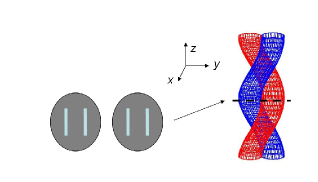
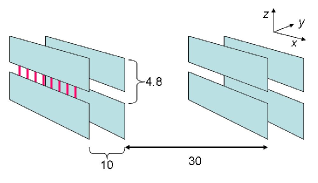
An amyloid fiber consists of intertwining filaments with a cross-beta sheet core structure Dobson et al. (2003). Within the cross-beta sheet core, the beta strands are separated by 4.8Å along the fibril axis. With the help of the carefully determined electrons density map for insulin fibrils in Jiménez et al. (2002), we have a relatively good idea on the location of the cross-beta sheets in the TFIF (c.f. Fig. 1). Specifically, experimental observations Bouchard et al. (2000); Jiménez et al. (2002) suggest that (i) the beta sheets are in the parallel configuration; (ii) there is a gap of 10Å between the two layers of beta-sheets within each filament; and (iii) the electrons density map suggests that there is a gap of about 30Å between the two filaments. These facts suggests that a structural model in which the TFIF is a doube-helix where each filament consists of two layers of cross-beta sheets (c.f. Figs. 1 and 2).
II Persistence length
In this section, we discuss the persistence length of the TFIF. The formalism developed in Panyuko and Rabin (2000a, b) indicates that for a ‘rod-like’ helical ribbons, the persistence length, , is of the form:
| (1) |
where is the bending stiffness and is the splaying stiffness of the ribbons. For the cross-section indicated by the black line in Fig. 1, refers to bending about the -axis and refers to bending about the -axis. Due to the gap of Å between the two filaments in the direction (c.f. Fig. 2), we expect that bending about the -axis is much more difficult than bending about the -axis, i.e., . We will therefore further simplify the expression for to .
To get an idea on the magnitude of for a generic two-layer beta-sheet, we look at the simulation results in Park et al. (2006) on a bilayered anti-parallel beta-sheets formed with a 16-amino-acid peptides (RAD16). In Park et al. (2006), the splaying stiffness for RAD16 is found to be about Nm2 Park et al. (2006). As we have stipulated that the splaying stiffness dictates the persistence length, the persistence length of m as measured in Smith et al. (2006) suggests that the splaying stiffness for TFIF is about Nm2. In other words, the for TFIF is approximately of that of RAD16, which in turn suggests that the width of the TFIF’s beta-sheet is about of that of RAD16, i.e., the TFIF’s beta-sheet is 7.6 to 8.6 amino-acides in length. This correlates reasonably well with the structure promoted in Jiménez et al. (2002) where the beta-sheet core structure consists of alternating insulin A chain (21 amino-acid long) and B chain (30 amino acid long). The above comparison is of course only valid if the hydrogen bond networks are solely responsible for the elastic properties of TFIF. This assumption is supported by simulation studies in Park et al. (2006) and experiments Knowles et al. (2007). Another caveat here is that the RAD16 has an anti-parallel beta-sheet structure while the TFIF has a parallel beta-sheet structure. We have therefore implicitly assumed that the elastic properties is independent of the beta-sheet directional arrangement. This assumption is again supported by previous theoretical work Chou (1985) and recent experimental work Knowles et al. (2007).
III Elasticity
In Knowles et al. (2007), a Gaussian network model (GNM) is introduced to account for the general mechanical properties of amyloid fibril. In the GNM, the spring constant of each hydrogen bond, , is taken to be about 12N/m Chou (1985). This spring constant estimate is corroborated by the simulation results in Park et al. (2006) where the stretching stiffness is found to be about N for RAD16, which suggests that each hydrogen bond has a spring constant of N/m. For the TFIF, if we assume that i) the spring constant for an hydrogen bonds is 10N/m, ii) there are 8 hydrogen bonds per cross-beta sheet (c.f. the previous section), iii) the area of cross section is nm2 Smith et al. (2006), and iv) the separation between each array of intersheet hydrogen bonds is 4.8Å. With these assumptions, the Young’s modulus of the TFIF can be estimated to be about 13GPa. This is close to the value GPa, which is suggested to be the Young’s modulus for a generic amyloid fibril based on the GNM Knowles et al. (2007). On the other hand, the measured value for the TFIF’s Young’s modulus by atomic force microscope experiment is GPa Smith et al. (2006). Besides the difference in the predicted and measured Young’s modulus, it is found in the simulation studies in Park et al. (2006) that the stretching elasticity of the RAD16 amyloid fibril is only linear within a very short range. Specifically, the extension elasticity is only linear when the extension is less than 0.1% of the original length. On the other hand, the AFM experiments performed in Smith et al. (2006) suggests that the elastic measurements are performed when the fibril is extended by more than 5% of its original length. These discrepancies may be explained by hydrogen bonds breakage under extension. To validate this picture and to further elucidate the exact nature of amyloid fibril’s elasticity, further experimental and theoretical work is required.
IV Conclusion
We have investigated the TFIF’s structure by incorporating the simulation results in Park et al. (2006), the GNM for amyloid fibrils introduced in Knowles et al. (2007), and the measurements on the mechanical properties performed in Smith et al. (2006). Our comparison studies suggest that the persistence length measurement correlates well with the structural model introduced in Jiménez et al. (2002), while the stretching elasticity measurement suggests that the extension of the fibril may involve complicated mechanism such as hydrogen bond breakage.
Acknowledgements.
The author thanks the Glasstone Trust and Jesus College (Oxford) for financial support.References
- Sunde et al. (1997) M. Sunde et al., J. Mol. Biol. 273, 729 (1997).
- Dobson et al. (2003) C. M. Dobson et al., Nature 426, 905 (2003).
- Radford (2000) S. E. Radford, Trends in Biochemical Sciences 25, 611 (2000).
- Sawaya et al. (2007) M. R. Sawaya et al., Nature 447, 453 (2007).
- Park et al. (2006) J. Park et al., Biophys. J. 90, 2510 (2006).
- Knowles et al. (2007) T. P. Knowles et al., Science 318, 1900 (2007).
- Smith et al. (2006) J. F. Smith et al., PNAS 103, 15806 (2006).
- Jiménez et al. (2002) J. L. Jiménez et al., PNAS 99, 9196 (2002).
- Bouchard et al. (2000) M. Bouchard et al., Protein Sci. 9, 1960 (2000).
- Panyuko and Rabin (2000a) S. Panyuko and Y. Rabin, Phys. Rev. Lett. 85, 2404 (2000a).
- Panyuko and Rabin (2000b) S. Panyuko and Y. Rabin, Phys. Rev. E 62, 7135 (2000b).
- Chou (1985) K. C. Chou, Biophys. J. 48, 289 (1985).