Commissioning of the Dual-Beam Imaging Polarimeter for the UH 88-inch telescope
Abstract
In this paper we present the design, calibration method, and initial results of the Dual-Beam Imaging Polarimeter (DBIP). This new instrument is designed to measure the optical polarization properties of point sources, in particular Main Belt asteroids. This instrument interfaces between the Tek camera and the University of Hawaii’s 88-inch telescope, and is available for facility use. Using DBIP we are able to measure linear polarization with a 1-sigma Poisson signal noise of per measurement and a systematic error of order . Additionally, we discuss measurements of the polarization of the asteroid 16 Psyche which were taken as part of the instrument commissioning. We confirm Psyche’s negative polarization of but find no significant modulation of the signal with rotation above the polarization level.
1 Introduction
Optical polarimetry of asteroids enjoyed a rush of activity in the 1960s and 1970s until the limits of the optics and imagers were reached. A resurgence of interest in polarimetric imaging of asteroids then appeared, fueled by previous successes with optics such as retarders and Savart plates (e.g. Serkowski (1974)) as well as improved CCD technology. Polarimetric studies of asteroids require large amounts of telescope time spread out over many nights to fully cover rotation periods and phase angles. The University of Hawaii’s 88-inch telescope offers our study the best access to a wide range of observing nights, but does not have a high precision polarimeter. We present the design and calibration results for a new instrument: the Dual-Beam Imaging Polarimeter (DBIP) for the UH 88-inch telescope which is capable of simultaneously measuring both orthogonal polarization states for point sources to an accuracy of better than . The observing scheme has been designed to make these measurements independent of flat field effects as well as changes in seeing or extinction. DBIP was commissioned in March of 2007 in half-wave mode, allowing measurement of linear polarization (Stokes vectors). Two polarized standards and two unpolarized standards were observed, as well as hours of coverage of the asteroid 16 Psyche, which has shown weak variations in polarization in the past (Broglia & Manara, 1992). In August 2007, DBIP will be commissioned in Full Stokes mode, providing sensitivity to Stokes while still retaining flat field and temporal independence.
2 Instrument Design
The optical design of DBIP centers on a double-calcite Savart plate. Calcite splits an incident beam into two parallel beams with orthogonal polarizations, called the ordinary (o) and extraordinary (e) beams. The e-beam has a slightly longer optical path in the calcite, producing differential aberrations. A Savart plate is two calcite blocks bonded with the e and o beams reversed, ensuring that the two beams have the same optical path length and same aberrations. The Savart plate used for DBIP was originally used for Near-IR imaging polarimetry (Hodapp & Rayner, 1991), but maintains its polarization properties in the optical regime. It has a beam separation of mm, which scales to arcseconds (pixels) on the Tek CCD. As currently mounted the two beams are rotated slightly clockwise of a North-South orientation, however we will refer to them as the northern and southern beams throughout this paper.
Because of this relatively small separation, DBIP is most useful for measuring point source polarization, and is incapable of measuring field polarization (including flat field polarization). However, as will be discussed in § 4, the power of a dual-beam system is that when used correctly the polarization values determined are independent of both flat field and temporal variations.
By rotating the Savart plate, all linear polarization angles could be explored, however this would mean that the direction of separation of the images would be dependent on the angle being investigated, which negates the flat-field independence provided by the Savart. Instead, a half-wave plate is inserted just before the Savart plate allowing the plane of polarization of the incident beam to be rotated. Once retarded by the half-wave plate, the transmitted intensity of the two beams exiting the Savart plate are
where is the total intensity, is the Stokes Q vector amplitude, is the Stokes U vector amplitude, is the angle of rotation of the waveplate, and is the throughput light amplitude in each of the two split beams.
Thus by rotating the half-wave plate any angle of polarized light can be sampled by the Savart plate while the image separation and orientation remains constant. There are a few different designs for half-wave plates (Pancharatnam, 1955; Goodrich, 1991), but a true zero-order retarder was chosen because they tend to have fairly flat retardance across a broad range of wavelengths and are available off-the-shelf for small (e.g. inch) diameters. Our half-wave plate is a birefringent polymer supplied by the Bolder Vision Optik company and provides a retardance of wavelengths over thenm wavelength range111quote from vendor’s website: http://www.boldervision.com/achro.html. Beginning with the expansion from the Muller matrix for a simple retarder-polarizer setup, we have the equation:
where is the retardance and is the angle of waveplate rotation. If the retardance varies between and wavelengths, this means that varies between . Using these maximal values for and a waveplate rotation angle of , the transmitted intensity will be:
which corresponds to a depolarization of the incident polarization (compared to the nominal for an ideal half-wave plate), as well as some separation of Stokes into the positive and negative beams. The Savart plate is insensitive to Stokes and thus this term can be neglected. It can be shown that Stokes will have depolarization systematics of the same order (). Thus for a polarized standard star we expect any retardance variation to manifest as a difference of in the measured percent polarization. A source with polarization (e.g. asteroids near their maximum negative polarization phase angle) will be measured as more depolarized than it actually is. Both of these (as shown below) fall well within our current limits for systematic polarization effects. This systematic depolarization would affect absolute polarization measures, and can be calibrated out with a large number of polarized standard star observations. This should not affect relative polarization measurements using a consistent filter and waveplate rotation angles.
An IR-blocked clear filter is chosen to restrict the observations to optical wavelength bands. The filter was supplied by the Custom Scientific company and has transmission in the nm range (typically ) and no throughput beyond that range. This is the closest analog to a Sloan g’+r’ filter that could be found both off-the-shelf and reasonably priced. Ideally the filter would be located after the Savart plate along the optical axis to prevent stray polarization signals from it, however due to physical space constraints within the mount it could only be located between the half-wave plate and the Savart plate. Should the filter generate any false linear polarization signal, unpolarized standard star calibrations should be able to detect this and remove it from measurement results. The biggest problem that could result from this placement of the filter would be if the filter had a tendency to act like a retarder. This could cause low levels of systematic depolarization, which would show up in the measurements of the absolute polarization of the polarized standard stars. A diagram of the optical configuration can be seen in Fig 1.
We chose to optimize DBIP for polarization analysis of point sources, and so wide field capabilities are not required. This meant we are not restricted by optical elements that vignetted the field of view and thus used less expensive, off-the-shelf components when available. Our inch diameter (inch clear aperture) half-wave plate is significantly smaller than the Tek CCD, which causes the field of view to be vignetted from the standard arcmin-sided square to a arcmin clear aperture. A benefit of this is that DBIP only requires the central pixels to be read out, reducing readout time to seconds.
To make this design as cost- and time-efficient as possible, we chose to use as many existing materials as possible. To mount our optics to the telescope, we used a mount fabricated for the QUIRC camera (Hodapp, et al., 1996). This mount attaches directly to the UH 88-inch telescope guider and only required minor modification to support the Tek camera. A spacer was made to hold the Savart plate, a bridge to hold the shutter, and the removable stage was altered to support the rotation stage and filter. We used a Newport PR50 series rotation stage with the accompanying SMC100 controller to rotate the waveplate. The PR50 model has a built-in rotary encoder allowing for tracking of the absolute position of the rotation stage, as opposed to open loop models which can only track the relative position to the device. The rotation stage has an angular resolution of and a guaranteed absolute motion accuracy of .
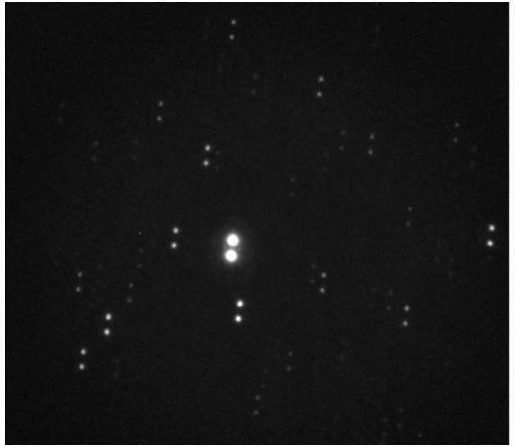
The first-light image from DBIP is shown in Fig 2. The nature of the split image, as well as the separation and entire field of view of the instrument can be seen in this picture.
3 Calibration
One of the biggest challenges in calibrating DBIP was finding published lists of polarized and unpolarized standard stars that would not saturate the detector in less than a second, i.e. a magnitude limit of mag. Most lists of polarized standards are brighter than this limit, and thus most useful for spectropolarimetry (e.g. Keck/LRISp222http://www2.keck.hawaii.edu/inst/lris/polarimeter/polarimeter.html; Subaru/FOCAS333http://www.naoj.org/Observing/Instruments/FOCAS/pol/calibration.html; Hubble (Schmidt, et al., 1992)). Fossati, et al. (2007) provide a list of polarized standards that fall within our required magnitude range, however most of these are in the Southern Hemisphere, and thus difficult to observe from Mauna Kea. From their list we are able to find two unpolarized standards adequately observable from our location, as well as two standards polarized at the and level. When the peak pixel value of each image of the target is kept near 45,000 counts the total beam will include counts, which will have a 1-sigma Poisson noise of . This flux level can be reached for a Vmag target in seconds, or seconds for a Vmag target. In terms of faint limits, DBIP can reach this flux level for a Vmag source with a min exposure time. Once both beams of the four images required to determine the linear polarization are combined, DBIP can measure percent polarization with a photon noise error of on an individual measurement. Multiple sets of observations allow us to reach Poisson noise errors of for our standard stars.
Target information, as well as literature and observed values for the percent polarization (Pol) and the angle of polarization () are given in Table 1. The difference between the observed and literature position angles are also given. It should be noted that our measurements show that HD 64299 is polarized at the level. HD 64299 was first reported as an unpolarized standard by Krautter (1980), with a polarization of . Turnshek, et al. (1990) report HD 64299 as an unpolarized standard with polarization (in the filter) of . These values are consistent (within ) with our observed measurement of polarization, however we are unable to determine at this point whether this polarized signal is due to low level systematics or is a true signal. Note that the errors given are for Poisson noise only. Systematic errors in our instrument are discussed below. Wardle & Kronberg (1974) discuss in their appendix the effect of the non-Gaussian distribution of errors on the measurement of percent polarization and angle of polarization. These effects are important for low-to-moderate signal-to-noise ratios, however our observations are at a S/N, well above this regime. Thus these effects have not been incorporated in our quoted errors of P.
Based on our observations of the two polarized standard stars, we find an offset in the angular alignment of the optics to be in the positive direction (East-of-North), where the error in this measurement is dominated by the errors on the literature values of angle of polarization. This offset of should be subtracted from all angular measurements before analysis. Our observations of WD 1615-154 result in a percent polarization measurement of , consistent with a zero result, and indicative of low-to-no systematic increase in polarization due to the optics.
The Cassegrain stage on UH 88-inch telescope has the ability to rotate, allowing the angle of the instrument on the sky to be changed. Restrictions due to cabling only allow coverage over the range of to from North, but because of the symmetry in the polarization vectors, this is sufficient to develop a full model of the polarization with instrument rotation, and thus investigate any residual polarization signal imparted by the telescope’s primary and secondary mirrors. We took measurements of HD 64299 and NGC 2024-1 across the range of instrument rotation angles to test for this signal. Figures 3 and 4 show the changes in the fractional polarization of , , and the total polarization for various Cassegrain stage rotation angles for HD 64299 and NGC 2024-1 respectively. Because the polarization signal from HD 64299 was seen to be fixed with respect to the sky when the Cassegrain stage was rotated, and not with respect to the instrument, the measured polarization is not due to an inherent systematic error created by one of the optical elements (e.g. the filter). In order to differentiate a polarization induced by the telescope’s mirrors with a true signal, observations of a number of polarized standards with a range of position angles is required. This will be the goal of a future calibration campaign using this instrument.
We find that there are variations in the polarization measurement with rotation, with an amplitude of for a polarized source and for a polarized source. This systematic error, however, does not change smoothly with instrument angle, nor are the variations the same for both targets. Thus until we perform further observations we can only quote an estimated amplitude of order for our systematic errors. This error includes effects from the telescope mirrors as well as from any misalignment in the optics or dust on the optical surfaces. This source of error is larger than the photon Poisson error, and will affect absolute polarization measurements and limit our accuracy when compared with literature values, however relative polarization measurements should be unaffected by this error. Additionally, we see no systematic depolarization that would indicate retarder-like behavior from the filter or deviation from wave retardance in the waveplate at a level greater that the above quoted limits.
4 Image Reduction
Analysis of the data taken during the commissioning run is done using IDL. Images are loaded in blocks of four (Q1, Q2, U1, U2) matching the pattern they were obtained by the camera control script. The designations Q1, Q2, U1, and U2 represent, respectively, waveplate rotation angles of , , , and with respect to the Savart plate orientation. The user is then required to click on the Northern-most image of the target in the displayed frame, this being the only user-dependent section of the reduction. The program then centers on both images of the target, subtracts off the appropriate region of the bias image and sums the signal in a pixel box around the target. This traces to a box on a side, which encompasses the radius of the PSF given an worse-than-average seeing of . The box around the orthogonal beam begins at the radius, meaning the cross-contribution between the beams is minimal. Figure 5 shows a comparison between sample data (solid line), a best-fit 2D Gaussian PSF (dashed line) and the limits of the pixel box. Though the PSFs are aligned in the y-direction on the CCD, we have shown cuts in the x-direction to better illustrate the overlap between the beam-split PSFs. In Fig 6 we show a close-up of the edges of the PSF wings, with both the fit and the box cut displayed as above. The data drop to a level comparable to the background noise before reaching the orthogonal beam’s integration box, meaning that beam cross-talk is not a significant systematic error. This is dependent on both the focusing of the telescope and the seeing during the observations. Our commissioning nights had a seeing of , which is worse than average for Mauna Kea (average of ), meaning bleeding between the PSFs will not be a problem for most observing nights.
The background level is determined by taking the median of a box of pixels in the direction away from the oppositely polarized beam. The error on this median is counts per pixel or counts over the region the signal is summed over, while the Poissonian error of the signal is of order counts. Thus the shot noise dominates our photometry error. This median background count is subtracted from each pixel.
We then calculate the total fractional polarization for both the Q and U states using the equations
where is the signal in an image and and subscripts refer to the positive (Northern) and negative (Southern) images, respectively. The fractional polarizations and are equivalent to and without assuming constant seeing or extinction between images. It is trivial to show that using this reduction method flat-field effects are canceled out, assuming the location of the image has not changed significantly between images and thus the flat fields at e.g. and are the same.
5 Observations of 16 Psyche
During the dates of DBIP’s commissioning, the Main Belt asteroid 16 Psyche, an M-type object, was near its phase of maximum negative polarization (Broglia & Manara, 1992; Giorgini, et al., 1996). We observed Psyche to show an overall polarization of , where a negative polarization value refers to polarization parallel to the Sun-Object-Earth plane and a positive polarization refers to polarization orthogonal to this plane. The error quoted here is noise-related only and does not account for any systematic offsets. The cause of negative polarization is second-order scattering of the light by particles on the asteroid’s surface (Muinonen, 1989). Table 2 lists the mean RA and Dec of Psyche on each night of observing, as well as the apparent V magnitude, the mean phase angle (), and the measured percent polarization.
Previously, Broglia & Manara (1992) reported variations in the polarized light curve with amplitude of at a confidence level. We observed Psyche during the commissioning to verify this measurement at a greater confidence level. However, we are unable to detect any modulation of Psyche’s polarization with rotation phase at any confidence for a amplitude variation. Figure 7 shows the data from the two nights of observing wrapped onto a rotation period of days (Broglia & Manara, 1992). Our observations are consistent with a constant polarization of and limit any amplitude of variation to . It is possible that the discrepancy between our measurements and those of Broglia & Manara (1992) could be the result of changes in pole orientation. De Angelis (1993) measured Psyche’s pole orientation to be , in ecliptic coordinates. During our observations Psyche was at an ecliptic longitude of , and thus a pole angle of while during the observations of Broglia & Manara (1992) Psyche was at an ecliptic longitude of , and thus a pole angle of (Giorgini, et al., 1996). Because our viewing orientation of Psyche is more pole-on than that of Broglia & Manara (1992) it is expected that we would see less variation across the surface with rotation than those authors. Because polarization is linked to albedo, and thus surface properties, this may explain our null result in looking for rotational variation in Psyche’s polarization. Conversely, if the region of Psyche’s surface that generated the polarization oscillation is in Psyche’s Southern hemisphere, it would have been observable during the observing period of Broglia & Manara (1992) but not during ours.
6 Conclusions
The Dual-Beam Imaging Polarimeter, a new instrument available on the UH 88-inch telescope using the Tek camera, has been commissioned in half-wave setup and is now available for facility use. We find that DBIP is able to measure percent polarization for a mag source with an exposure time of seconds to accuracies of from a single set of the four observations required to determine the linear Stokes parameters. This level can likewise be reached for a Vmag target in seconds to a limit of Vmag for a 15 minute exposure time. These measurements are independent of flat-field, seeing, or extinction effects. Estimates of the systematic polarization offset due to the telescope’s mirrors place the errors at .
We set an upper limit to the rotational variation of the polarized signal of the Main Belt asteroid 16 Psyche at , much lower than previously published results. We postulate that this difference is due to changes in pole orientation from previous observations to ours.
DBIP will be commissioned in full-Stokes mode during Aug 2007, when a quarter-wave plate will be installed in addition to the half-wave plate to provide sensitivity to both linear and circular polarization using sets of 6 images at various rotation angles for both waveplates.
7 Acknowledgments
The authors wish to thank Colin Aspin for providing the half-wave plate, Ed Sousa for example control code, and Richard Shelton for help in the machine shop. All of the above also provided a large amount useful advice that allowed us to bring this instrument into existence. Additionally, we would like to thank Rolf-Peter Kudritzki, Shadia Habbal and the entire IfA for funding support, Nathan Huisman for computer support, and Robert Jedicke for letting JRM take time off his thesis to get this built. Additionally, we thank the anonymous referee for helpful comments that greatly clarified this paper.
References
- Broglia & Manara (1992) Broglia, P. & Manara, A., 1992, “A study of the polarimetric lightcurve of the asteroid 16 Psyche”, A&A, 257, 770.
- De Angelis (1993) De Angelis, G., 1993, “Three asteroid pole determinations”, P&SS, 41, 285.
- Fossati, et al. (2007) Fossati, L., Bagnulo, S., Mason, E., Landi Del’Innocenti, E., 2007, “Standard Stars for Linear Polarization Observed with FORS1”, ASP Conf., 364, 503.
- Giorgini, et al. (1996) Giorgini, J.D., Yeomans, D.K., Chamberlin, A.B., Chodas, P.W., Jacobson, R.A., Keesey, M.S., Lieske, J.H., Ostro, S.J., Standish, E.M., Wimberly, R.N., 1996, “JPL’s On-Line Solar System Data Service”, Bulletin of the American Astronomical Society 28(3), 1158.
- Goodrich (1991) Goodrich, R.W., 1991, “High-Efficiency ’Superachromatic’ Polarimetry Optics for Use in Optical Astronomical Spectrographs”, PASP, 103, 1314.
- Hodapp, et al. (1996) Hodapp, K.-W., et al., 1996, “The HAWAII Infrared Detector Arrays: testing and astronomical characterization of prototype and science-grade devices”, New Astronomy, 1, 177.
- Hodapp & Rayner (1991) Hodapp, K.-W. & Rayner, J., 1991, “The S106 star-forming region”, AJ, 102, 1108.
- Krautter (1980) Krautter, J., 1980, “Polarization Measurements of 313 Nearby Stars”, A&AS, 39, 167.
- Muinonen (1989) Muinonen, K., 1989, “Electromagnetic Scattering by Two Interacting Dipoles”, Proc. URSI International Symp. on Electromagnetic Theory, 428.
- Pancharatnam (1955) Pancharatnam, S., 1955, “Achromatic Combinations of Birefringent Plates. Part II. An Achromatic Quarter - Wave Plate”, Proc. Indian Acad. Sci., A41, 137.
- Schmidt, et al. (1992) Schmidt, G.D., Elston, R., & Lupie, O.L., 1992, “The Hubble Space Telescope Northern-Hemisphere Grid of Stellar Polarimetric Standards”, AJ, 104, 1563.
- Serkowski (1974) Serkowski, K., 1974, “Polarization Techniques”, Methods of Experimental Physics, ed. N. Carleton, Vol 12A: Astrophysics, 361.
- Turnshek, et al. (1990) Turnshek, D.A., Bohlin, R.C., Williamson II, R.L., Lupie, O.L., Koornneef, J., & Morgan, D.H., 1990, “An Atlas of Hubble Space Telescope Photometric, Spectrophotometric, and Polarimetric Calibration Objects”, AJ, 99, 1243.
- Wardle & Kronberg (1974) Wardle, J.F.C & Kronberg, P.P., 1974, “Linear Polarization of Quasi-Stellar Radio Sources at 3.71 and 11.1 Centimeters”, ApJ, 194, 249.
| UT Obs Date | name | V mag | RA | Dec | Lit Pol | Lit | Obs Pol | Obs | |
|---|---|---|---|---|---|---|---|---|---|
| 03-23-2007 | HD 64299 | 10.11 | 07:52:25.51 | n/a | n/a | ||||
| 03-24-2007 | WD 1615-154 | 12.40 | 16:17:55.25 | n/a | n/a | n/a | |||
| 03-24-2007 | NGC 2024-1 | 12.17 | 05:41:37.85 | ||||||
| 03-24-2007 | BD-12 5133 | 10.40 | 18:40:01.70 |
Note. — Literature values for polarized and unpolarized standards taken from Fossati, et al. (2007).
| UT Obs Date | Mean RA | Mean Dec | V mag | Mean | Measured Pol |
|---|---|---|---|---|---|
| 03-23-2007 | 10:41:25 | 10.77 | |||
| 03-24-2007 | 10:40:45 | 10.79 |