Controlled enhancement or suppression of exchange biasing using impurity -layers
Abstract
The effects of inserting impurity -layers of various elements into a Co/IrMn exchange biased bilayer, at both the interface, and at given points within the IrMn layer a distance from the interface, has been investigated. Depending on the chemical species of dopant, and its position, we found that the exchange biasing can be either strongly enhanced or suppressed. We show that biasing is enhanced with a dusting of certain magnetic impurities, present at either at the interface or sufficiently far away from the Co/IrMn interface. This illustrates that the final spin structure at the Co/IrMn interface is not only governed by interface structure/roughness but is also mediated by local exchange or anisotropy variations within the bulk of the IrMn.
pacs:
75.70.Cn, 75.60.-d, 75.50.LkI Introduction
The fascination with understanding exchange bias has shown no noticeable change, considering that 50 years have elapsed since its discovery by Meiklejohn and Bean.Meiklejohn&bean1957 This impetus is both practical and fundamental,Nogues2005 since the effect both forms the integral component of devices such as spin-valves, magnetic tunnel junctions, and more elaborate ‘spin electronic’ devices, as well as offering the opportunity to study frustrationAli2007 and the interactions of feromagnetic and antiferromagnetic order in low dimensions. The effect originates from the interfacial coupling of atomic spins across a ferromagnetic (F) and antiferromagnetic (AF) interface, the principal manifestation of which is a unidirectional anisotropy in the F layer.Mauri1987 ; Tang1981 ; Misra2004JAP The main characteristic features which arise from the phenomenon are the offset of the F magnetic hysteresis loop from zero, referred to as the exchange bias field (), and its associated coercivity enhancement ().
However, the precise microscopic mechanism which controls the interfacial coupling is still a somewhat contentious topic. Large amounts of both experimental and theoretical workReviews1 have highlighted the complexity of parameters which influence the effect. It is now evident that the simple model that was first proposed by Meiklejohn and Bean – which assumes an ideal smooth magnetically uncompensated surface containing a rigid spin structure – is inadequate in explaining the biasing. Foremost, such perfect interfaces do not exist in reality, but moreover this model is also unable to explain all the rich features associated with the effect, for instance, coercivity enhancementstiles2001 ; leighton2000PRL ; Blamire2007PRL and training effectsZhang2001 ; Ali2003 are common to all systems to varying degrees. It is also unable to address the asymmetrical reversal of the magnetization in such systems,leighton2000prl2 the AF layer thickness dependence,sang1999 ; lund2002 ; Ali2003 and the lower than expected experimentally obtained values for the exchange bias field. In spite of this, it does highlight that an offset in the hysteresis loop will only be permitted when the anisotropy of the antiferromagnet is adequately larger than the interlayer exchange coupling . The importance of the AF anisotropy was also demonstrated in an artificial exchange bias [Co/Ru]10/[CoPt/Ru]10 system, where the shift in the hysteresis loop was only shown to be present under these conditions Steadman2002 . It has also been demonstrated that the enhancement in the coercivity at both the onset and disappearance of biasing are due to these terms being similar in magnitude giving rise to a reversible magnetic component in the AF.Ali2003b
Several theoretical models have evolved based upon the formation of domains in the AF to reduce the coupling strength.Koon1998 ; Schulthess1999prb ; Schulthess1999apl ; Nowak2002 ; Malozemoff1988 ; Misra2004JAP ; Mauri1987 The most encouraging models have been those which involve random variations in the local biasing due to defectsNowak2002 ; Kim2005 or roughness,Malozemoff1988 the essence of which is to dilute the spins involved, reducing the anisotropy and the exchange interaction. However, at present the interface structure is generally assumed (with very few exceptionsstocks ) to be that of the bulk AF, the main reason being the extreme difficulty in experimentally ascertaining the precise structural and magnetic nature of the buried interface at the necessary atomic scale. Even for the most ideal samples it is hard to imagine that there will no re-ordering of the magnetic, crystallographic and chemical structure at the interface region. This will give rise to magnetic disorder and or spin dilution. It has been demonstrated, in an epitaxial Co/FeMn sample, how paramount the local atomic spin structure is on exchange bias.Kuch It was shown that the atomically flat planes did not play a role, whereas the monolayer steps (atomic scale roughness) that are present at the interface mediates the magnetic coupling across the interface. This may also resolve the quandary of why a nominally fully compensated AF surface is able to pin a ferromagnetic layer.Blamire
However, the bulk AF spin structure also plays an important role. Recent experiments have shown it is possible to manipulate the bias field by ion irradiation of the samples.Poppe2004 ; Mewes2000 ; Engel2005 ; Sampaio2005 ; Ehresmann2006 The experiments have demonstrated that it is possible to modify the exchange bias properties by manipulating the level of disorder depending upon the ion dose and energy, in line with recent theoretical models.Misra2004JAP In the majority of these experiments the complete system has undergone the irradiation process including the ferromagnet. Interestingly in all cases, the experiments have been undertaken in the presence of a external magnetic field. This implies that system is undergoing a local thermal treatment, where the biasing locally is being reset, hence the necessity for an applied field. From current theoretical models and accompanying experimental work, it is established that there are domains in the AF layer. However, there are still questions regarding the formation and type. Do the domains nucleate at the interface due to disorder, as in the domain model of Malozemoff,Malozemoff1988 or are they more in line with domain state model of Nowak et al.?Nowak2001
Another class of experiments is those where spacers are introduced between the F and AF layers. The exchange bias field is essentially dependent on the relative strengths of and , and this has been investigated by a number of groups where spacer layers have been introduced between the AF and F layers to manipulate the strength of the coupling.GokemeijierPRL1997 ; ThomasJAP2000 ; WangJAP2002 ; GarciaAPL2003 ; ErnultJAP2003 ; LiJAP2003 ; CaiPRB2004 These studies seem to indicate that exchange bias is not necessarily a consequence of a direct exchange (nearest-neighbor) coupling mechanism. There have been contradictory reports that the exchange bias across the spacer layer is long-range in nature and decays exponentially,GokemeijierPRL1997 whilst others have reported it to be either oscillatoryCaiPRB2004 or very short range in natureThomasJAP2000 , with any long range effects ascribed to the presence of pinhole defects in the spacer.
In order to provide further insight into these questions, we report in this article on the effects of inserting a -dusting of various elements to induce disorder at both the interface and in the bulk of the AF layer in a controlled manner. This was done by depositing a sub-monolayer of both magnetic and non-magnetic impurities in order to induce changes in the magnetic disorder on the atomic level.
II Experimental Methods
The Co/IrMn system was studied experimentally within a simple spin-valve structure. A series of exchange biased spin-valve films were deposited by dc magnetron sputtering at an argon working pressure of 2.5 mTorr. The base pressure prior to the deposition was of the order of Torr. The substrates used were Si(100) with the native oxide layer intact, cleansed in acetone and isopropanol. The samples were deposited at ambient temperature, and through masks to ensure a constant film area from sample to sample. The system allowed 15 samples to be deposited during the same vacuum cycle, which permitted 15 spin-valve structures Ta(75 Å)/Co(40 Å)/Cu(23 Å)/Co(26 Å)/IrMn( Å)/-layer/IrMn( Å)/Ta(50 Å) to each specimen set grown in indistinguishable conditions which eliminates, as far possible, sample-to-sample variations within a run: these variations are very small as can be seen in certain data sets later in the paper. However, there can be more noticeable variations in these properties from one sputtering run to the next. Hence, an important part of our experimental methodology is to prepare an undoped control sample in each run, to which the properties of the doped samples can be compared. In the data presented below for the and dependences on dopant layer thickness and position in Figs. 2-5, the 14 data points are the doped samples from a single sputtering run, whilst the dotted line indicates the values for these fields displayed by the control sample.
The IrMn was deposited from a Mn target with chips of Ir attached to its surface, and energy dispersive x-ray absorption spectroscopy yielded a composition in the deposited film of Ir25Mn75. Deposition rates were determined by measuring the thickness of test films by low angle x-ray reflectometry, and were typically in the range of 2-3 Å/s. X-ray diffraction showed that such samples are predominantly fcc with a (111) texture. We did not detect any changes in texture in a representative selection of doped samples measured by this technique, presumably since the -layers are so thin. No post annealing steps were required, since the pinning direction was set by a 200 Oe in-plane forming field applied to the sample during the deposition of all the layers in this top spin-valve configuration.
The distance from the AF/F interface to the dopant layer was zero in some cases, but could also be an experimental variable. An IrMn layer thickness of 120 Å was chosen for two reasons: the first being that it is thick enough that any fluctuations in the IrMn thickness would have a negligible effect on the exchange biasing, and the second is that it allowed the possibility of placing the impurity layer sufficiently away from the interface but still within the bulk of the layer to investigate disorder effects. Previous work has established an in-depth understanding of both the temperature and thickness dependence of the exchange bias for this Co/IrMn systemAli2003 . It has been shown that the critical thickness at which biasing is fully established is approximately 40 Å at room temperature. For greater thicknesses, the biasing effect is found to be constant in an undoped layer. The -layer method and the effects on giant magnetoresistance in spin-valvesmarrowsprb and interlayer coupling in multilayersperezepl has been previously described.
In comparison to the ion irradiation studies where the complete structure undergoes irradiation, the -dusting only generates disorder on the atomic length scale. This also allows information on the position dependence of the -dusting on exchange bias. Studies up to now have solely considered non-magnetic defects to produce disorder. A foreign magnetic impurity will also cause both structural and magnetic disorder through frustration for example besides being polarized. One should be aware that even though the particle size of the magnetic impurities will be in the paramagnetic regime the particle will have a Curie point dictated by its surrounding magnetic environment through proximity exchange effects. Hence, for particles within the IrMn layer, the Curie point would be that of the Néel point of the IrMn, in this case 250∘C.
The spin-valve structure allowed the free Co layer within the spin-valve to be used as a control layer, to which the properties of the exchange coupled Co layer could be directly compared. The effect of the free layer on the pinned layer properties was minimal: orange-peel coupling fields were never more than a few Oe. It also allowed magneto-transport measurements to be performed, the resistance measurements were done using a standard four point probe dc technique. Typical (300 K) magnetoresistances of our spin-valves were per cent, whilst typical (300 K) sheet resistances were 10 /square. Magnetic characterization was done using a Vibrating Sample Magnetometer (VSM) and a Magneto-Optical Kerr Effect (MOKE) apparatus. All the data we shall show for and were acquired at room temperature.
III Results and Discussion
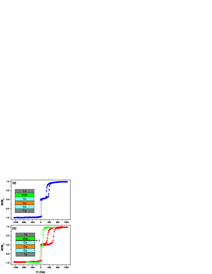
We begin by showing in Fig. 1 some hysteresis loops that illustrate the clear spin-valve switching in our samples, as well as the marked effects even small amounts of -dopant can have on the exchange bias in this system. In panel (a) we show the typical result obtained for an undoped “control” sample. The pinned and the free layer loops are easily identifiable, from which the exchange bias field and coercivity values are straightforwardly obtained by the usual means: is the offset of the pinned loop center from zero field, is half its width. The effects on exchange bias of a 1 Å Fe or Ta -layer at the AF/F interface are shown in panel (b). The most striking effect is the doubling of the exchange bias field for the introduction of the Fe, accompanied by an enhancement in . Using , where is the interfacial exchange energy per unit area, and are the magnetization and thickness of the ferromagnetic layer respectively, values of 0.17 mJm-2 and 0.35 mJm-2 are obtained for the interfacial exchange energy for the control and Fe-doped case, consistent with much stronger exchange bonds across the interfacial sites. Meanwhile, the introduction of Ta reduces the interfacial exchange energy to 0.07 mJm-2, consistent with Ta breaking interfacial exchange bonds between Co and IrMn sites. is reduced by the introduction of Ta.
In the rest of this paper we describe in detail the effects of a selection of dopants, placed at the Co/IrMn interface, and moved away from it into the IrMn layer, on and .
III.1 Interfacial -layers
The effect of placing the non-magnetic dopants Cu, Ta, Pt and Au at the Co/IrMn interface () on and is presented in Fig. 2 as a function of the dusting layer thickness. The solid lines are a guide to the eye and the horizontal dashed lines indicate the value of for the control samples without any -dusting. In general the exchange bias field decreases as the dusting becomes thicker. (Here the thickness is defined as the average equivalent thickness for the quantity of material deposited.) It is clear that materials that make good spacer layers for indirect exchange coupling via the RKKY mechanism such as Cu and Au, tend to suppress less rapidly compared to materials such as Ta. For the Ta dopant there is a monotonic decrease for thicknesses up to 1.5 Å, before rapidly collapses to zero at that point. Interestingly this length scale is significantly smaller than the equivalent thickness of a monolayer (3.3 Å), and therefore is unlikely to be a consequence of the formation of a continuous Ta layer.
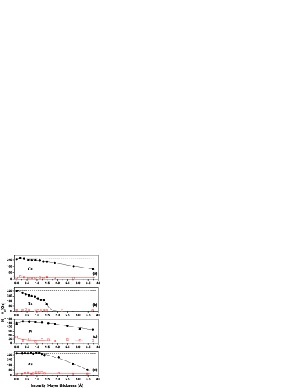
Extrapolating the curves for Cu, Pt and Au one finds that diminishes to zero at a dopant thickness of approximately 6 Å, 8 Å, and 4 Å respectively. These thickness are greater than that required to form a monolayer. It could be conceived that this is the point at which the dusting coalesces to form a continuous layer. This is feasible, since metallic superlattice structures have shown that it is indeed possible to obtain continuous spacer layers of the order of 2 monolayers.Parkin1991 The small length scales involved ( Å), clearly suggests that exchange interaction across the interface is very short range in nature, and so the biasing appears to be due solely to direct exchange interactions between spins in the F and AF layers. This is in sharp contrast to the findings of previous workGokemeijierPRL1997 where the exchange field was reported to exponentially decay over a length scale of Å. Keeping this in mind, it is even more puzzling why a dusting of 1.5 Å of Ta would destroy the biasing. As this must be less than a monolayer, leaving large areas of direct exchange between the Co and the IrMn layer. A possible explanation is that a Ta atom must destroy exchange bonds involving neighboring atomic sites as well as its own by creating an extended defect in the electronic structure. It should be noted in systems where Ta is placed for example next to permalloy (Ni81Fe19), that a chemical reaction takes place between the two layers giving rise to a dead layer. This has an effect of reducing the momentMoghadam2005 ; Yu2005 ; Yang2007 of the layer.
The Pt dusting however, also exhibits an additional feature where increases by above that for the control sample for a -dusting Å, before then gradually decreasing towards zero. This effect is remarkably similar to what has been observed in perpendicular exchange bias systems, where the addition of a Pt spacer layer is said to induce a better collinear alignment of the Co spins out of the plane.GarciaAPL2003 This gives rise to an increase in . In the present case the spins for both layers are confined to the easy plane of the film by the shape anisotropy. One possibility is that the Pt is substituting for the Ir, to form chemically ordered L10 phase of PtMn on a localized basis, which itself is an AF material. PtMn possesses a larger anisotropy, and is therefore able to orientate a larger number of Co spins to be collinear with the unidirectional anisotropy at the interface. This will have the effect of increasing . Further increments of Pt (0.4Å) simply reduces as with the other dopants, presumably by weakening interfacial exchange bonds.
Before moving on, we note that in all cases remains approximately constant for all dusting levels, indicating that there is no substantial change in the AF reversible spins in the bulk or interface, which is generally associated with any enhancement/reduction of .Ali2003b The lack of any enhancement even at the point where the biasing vanishes (Fig. 2(b)), is generally interpretated the point at which the biasing becomes reversible before vanishing with as a fuction of AF thickness or temperature Fulcomer1972 , would imply that the impurity is simply diluting/screening the exchange interaction of the spins which are associated with the biasing across the F/AF interface.
The effects on and of placing various magnetic dopants at the Co/IrMn interface is shown in Fig. 3. Since we would expect that increasing the total FM layer thickness by adding this material should give a dependence where , hence decreasing the bias field. Nevertheless, the most striking feature is the large increase in in the appropriate -layer thickness range for the 3 metals Fe, Ni and permalloy (Py = Ni80Fe20). For all these three, a broad peak in approximately at 1-2Å of dopant is observed. The insertion of the Fe dusting increases by some , whereas for NiFe it is and for the Ni dusting the rise is . As might be expected, the general form of the data for the NiFe alloy falls between those for the pure elemental Fe and Ni dopant layers. It is interesting to note that the magnetization of the pinned layer material, Co, falls between that of Fe and Ni. This means that Fe dopants will be increasing the surface magnetization of the pinned layer, whilst Ni dopants will reduce it. However both are capable of increasing the bias field above that for a control sample. This suggests that the increase in bias is somehow related to an inhomogeneous magnetic interface.
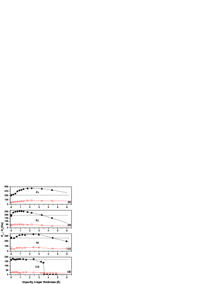
We have also used a 4 ferromagnet dopant, Gd, the moment of which is known to couple antiferromagnetically to that in 3 materials. The results for Gd are shown in the bottom panel of Fig. 3. Here the effect is quite different, with almost no change in the bias field until a critical thickness of about 3.5 Å, when drops abruptly to zero. This thickness corresponds roughly to a monolayer. Although the Gd was barely above its bulk Curie temperature of 293 K, we should expect that it has some ferromagnetic order as the moments will be in a strong exchange field from the Co with which it is in intimate contact. Hence it seems that the Gd moments do not couple to those in the IrMn which are responsible for biasing, although why this should be so is not clear to us at present. It should be noted that there was no evidence of any biasing at lower temperatures of a single Gd layer.
III.2 -layers in the bulk
The effects of inserting a non-magnetic -layer of 1 Å thickness into the AF layer a distance from the interface are shown in Fig. 4 for the same four dopant materials as in Fig. 2. In no case is there any increase in over the control samples. However, as the -dusting is moved into the IrMn for the first few Å away from the interface, decreases, accompanied by a slight increase in . As the -layer is moved further still from the interface, recovers to the value shown by the control samples once exceeds Å. The length scale of 20Å seems to be independent of the dusting material used. The magnitude of the dip in bias field seems again to be correlated to the indirect exchange coupling strength of the material as a spacer layer for RKKY coupling (Fig 2). Pt has the least effect, followed by Au, Cu, and then Ta, which also has a detrimental effect at the interface as shown in Fig. 2.
This implies the enhancement originates from a purely interfacial magnetic effect, and therefore cannot be a result of changes in the domains in the bulk of the AF of the type that is assumed in dilutionMiltenyi2000 or ion irradiation experiments.Poppe2004 ; Mewes2000 ; Engel2005 ; Sampaio2005 ; Ehresmann2006
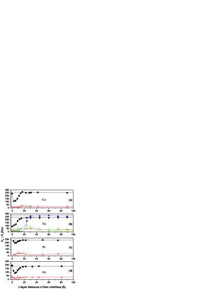
We also used a slightly greater dusting of 1.5 Å of Ta, which at the interface completely suppresses the biasing, but as the dusting is moved away from the interface reappears at approximately Å and fully recovers to that of the control samples by Å. We also found that there is peak in at the onset of , as is usual. This contradicts an investigation where a Au layer was moved away from NiO/Co interface,ErnultJAP2003 where it was found that the biasing totally disappeared as the Au layer was moved away from the interface. The effects of the thicker Ta layer bear a striking resemblance to the AF thickness studies that have been previously carried out on this materials system.Ali2003b Similar characteristic length scales are present for the onset and saturation of along with a peak in at the onset of biasing. This suggests that the Ta layer is thick enough here to divide the IrMn into two magnetically disconnected parts. Only the part that is adjacent to the FM layer contributes to the exchange bias, the other part plays no role.
The effects of moving a magnetic -layer of 1 Å thickness into the IrMn layer are shown in Fig. 5: the three elemental dopants used in the experiment reported in Fig. 3 appear here along with Co. The elements Gd and Co were seen to have no significant effect on either or for any value of . On the other hand, there is a clear dependence of these these two quantities on for the Ni and Fe layers to be seen in the data. The trend is similar to that of the non-magnetic -layers for small values of , where there is a dip in at approximately Å. However, as the layer is moved further from the interface not only does the biasing recover and saturate by 30 Å, the magnitude also increases in comparison to the control samples by 20% for Ni and 34% for the Fe. In general no obvious trend with the position of the -layer is evident in . There is enhancement in when the Fe is present at the interface, but this falls rapidly back to the control sample level once beyond 5 Å. This is also evident in Fig. 3, where a slight increase in is observed.
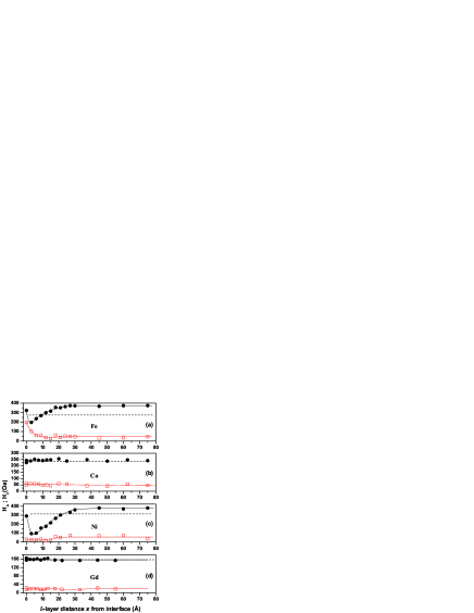
As with the non-magnetic elements, the dip in is attributed to the dilution of the interfacial magnetic moment and anisotropy for the Fe and Ni elements: given that these are magnetic elements we should not expect a significant depression in the local exchange interaction strength. One can speculate that the -layer is neutralizing the uncompensated moments associated with the biasing. It may be significant that whilst FeMn,ishikawa1974 CoMn,cable1994 NiMn,kren1968 and GdMngoncharenko2005 all have antiferromagnetic phases, only FeMn and NiMn show a significant exchange bias at room temperature.lin Exchange bias from antiferromagnetic CoMn is generally either non-existent or weak.huangjmmm2000 We are unaware of any reports of attempts to observe an exchange bias using a GdMn-based AF layers. At the interface the Fe and Ni simply couple F with the Co layer, whereas immediately within the IrMn layer they couple AF with the uncompensated spins in the vicinity of the interface, in this manner effectively reducing the net interfacial magnetization. Elements such as Au or Cu reduce the biasing because they possibly form the classical spin glass phases of CuMnAli2007 and AuMn. At room temperature the spin glass would behave as paramagnetic entity and similarly reduce the net interfacial magnetization. For these reasons one might obtain a dip in as function of position. Away from the interface the Ni and Fe create an additional AF system (FeMn/NiMn) within the IrMn which enhances the biasing. What is intriguing is the lack of any effect of the Co or Gd on the -layer position. One can only infer that the Co and the Gd atoms are easily accommodated into the magnetic structure of the IrMn layer for the dusting levels employed and therefore have a negligible effect on the local anisotropy.
The results of Fe and Ni seem to suggest that not only is the interfacial anisotropy paramount for exchange biasing (the dip), but the final magnetic state is also influenced by the bulk magnetic state of the AF layer due to the enhancement in beyond 30 Å. These results seem to be in agreement with the diluted domain state models and the ion irradiation experiments.
IV Conclusion
We have shown that magnetic disorder is a key ingredient in understanding the exchange bias phenomenon by studying the effects of inserting impurity -layers of various elements at both the Co/IrMn interface and at given points within the IrMn layer itself. The experiments have shown the importance of disorder in the vicinity of the interface and throughout the bulk of the AF layer, and is consistent with the domain state model. By using both magnetic and non magnetic -layers, it is possible to conclude that it is the magnetic disorder which seems to dominate and control the exchange bias effect. Any effect which is able to generate magnetic disorder will therefore influence the exchange bias. In general non-magnetic elements were found to reduce the exchange coupling, the exception being Pt where larger anisotropies are induced. On the other hand, when placed correctly, the magnetic elements induced a stronger exchange bias due to the increase in magnetic disorder by inducing stronger exchange bonds or anisotropy at the doped atomic sites. Overall, we have observed a rich variety of behavior that we hope will provide a spur to the development of theories that treat disorder in exchange bias systems. Also, these results demonstrate a means of tailoring and improving the magnitude of exchange anisotropy in device applications.
Acknowledgements.
This work was supported by the EPSRC.References
- (1) W. H. Meiklejohn and C. P. Bean, Phys. Rev. 105, 904 (1957).
- (2) J. Nogués, J. Sort, V. Langlais, V. Skumryev, S. Surinach, J. S. Munoz, and M. D. Baro, Phys. Rep. 422, 65 (2005).
- (3) M. Ali, P. Adie, C. H. Marrows, D. Greig, B. J. Hickey and R. L. Stamps, Nature 6, 70 (2007).
- (4) A. Misra, U. Nowak, and K.D. Usadel, J. Appl. Phys. 95, 1357 (2004).
- (5) D. Mauri, H.-C. Siegmann, P. S. Bagus, and E. Kay, J. Appl. Phys. 62, 3047 (1987).
- (6) C. Tang, N. Heiman, and K. Lee, J. Appl. Phys. 62, 2471 (1981).
- (7) J. Nogués and I. K. Schuller, J. Magn. Magn. Mater. 192, 203 (1999); A. E. Berkowitz and K. Takano, J. Magn. Magn. Mater. 200, 552 (1999).
- (8) M. Stiles and R. D. McMichael, Phys. Rev. B 63, 064405 (2001).
- (9) C. Leighton, J. J. Nogués, B. J. Jönsson-Åkerman, and I. K. Schuller, Phys. Rev. Lett. 84, 3466 (2000).
- (10) M. G. Blamire, M. Ali, C.-W. Leung, C. H. Marrows, and B. J. Hickey, Phys. Rev. Lett. 98, 217202 (2007).
- (11) K. Zhang, T. Zhao, and H. Fujiwara, J. Appl. Phys. 89, 2471 (2001).
- (12) M. Ali, C. H. Marrows, and B. J. Hickey, Phys. Rev. B 67, 172405 (2003).
- (13) M. R. Fitzsimmons, P. Yashar, C. Leighton, Ivan K. Schuller, J. Nogués, C. F. Majkrzak, and J. A. Dura, Phys. Rev. Lett. 84, 3986 (2000).
- (14) H. Sang, Y. W. Du, and C.-L. Chien, J. Appl. Phys. 85, 4931 (1999).
- (15) M. S. Lund, W. A. A. Macedo, K. Liu, J. Nogués, I. K. Schuller, and C. Leighton, Phys. Rev. B 66, 054422 (2002).
- (16) P. Steadman, M. Ali, A. T. Hindmarch, C. H. Marrows, and B. J. Hickey, Phys. Rev. Lett. 89, 077201 (2002).
- (17) M. Ali, C. H. Marrows, M. Al-Jawad, B. J. Hickey, A. Misra, U. Nowak, and K. D. Usadel, Phys. Rev. B 68, 214420 (2003).
- (18) N. C. Koon, Phys. Rev. Lett. 78, 4865 (1998).
- (19) T. C. Schulthess and W. H. Butler, Phys. Rev. B. 85, 5510 (1999).
- (20) T. C. Schulthess and W. H. Butler, J. Appl. Phys. 59, 3722 (1999).
- (21) A. P. Malozemoff, Phys. Rev. B 35, 3679 (1987); ibid. 37, 7673 (1998); J. Appl. Phys. 63 3874 (1988).
- (22) U. Nowak, A. Misra, and K. D. Usadel, J. Magn. Magn. Mater. 240, 243 (2002).
- (23) J.-V. Kim and R. L. Stamps, Phys. Rev. B 71, 094405 (2005).
- (24) G. M. Stocks, W. A. Shelton, T. C. Schulthess, B. Ujfalussy, W. H. Butler, and A. Canning, J. Appl. Phys. 91, 7355 (2002).
- (25) W. Kuch, L.I. Chelaru, F. Offi, J. Wang, M. Kotsugi, and J. Kirschner, Nature Mat. 5, 128 (2006).
- (26) M. G. Blamire and B.J. Hickey, Nature Mat. 5, 87 (2006).
- (27) S. Poppe, J. Fassbender, and B. Hillebrands, Europhys. Lett. 66, 430 (2004).
- (28) T. Mewes, R. Lopusnik, J. Fassbender, B. Hillebrands, M. Jung, D. Engel, A. Ehresmann, and H. Schmoranzer, Appl. Phys. Lett. 76, 1057 (2000).
- (29) D. Engel, A. Ehresmann, J. Schmalhorst, M. Sacher, V. Hoink, and G. Reiss, J. Magn. Magn. Mater. 293, 849 (2005).
- (30) L. C. Sampaio, A. Mougin, J. Ferre, P.Georges, A. Brun, H. Bernas, S. Poppe, T. Mewes, J. Fassbender, B. Hillebrands, Europhys. Lett. 63, 819 (2003).
- (31) A. Ehresmann, D. Engel, T. Weis, A. Schindler, D. Junk, J. Schmalhorst, V. H ink, M. D. Sacher, and G. Reiss, Phys. Stat. Sol. (b) 243, 29 (2006).
- (32) U. Nowak, A. Misra, and K. D. Usadel, J. Appl. Phys. 89, 3874 (2001).
- (33) N. J. Gökemeijer, T. Ambrose, and C.L. Chien, Phys. Rev. Lett. 79, 4270 (1997).
- (34) L. Thomas, A.J. Kellock, and S.S.P. Parkin, J. Appl. Phys. 87, 5061 (2000).
- (35) J. Wang, W.N. Wang, X. Chen, H.W. Zhao, J.G. Zhao, and W.S. Zhan, J. Appl. Phys. 91, 7236 (2002).
- (36) F. Garcia, J. Sort, B. Rodmacq, S. Auffret, and B. Dieny, Appl. Phys. Lett. 83, 3537 (2003).
- (37) F.Ernult, B. Dieny, L. Billard, F. Lancon, and J.R. Regnard , J. Appl. Phys. 94, 6678 (2003).
- (38) K. Li, Z. Guo, G. Han, J. Qui, and Y. Wu, J. Appl. Phys. 93, 6614 (2003).
- (39) J.W. Cai, W.Y. Lai, J. Teng, F. Shen, Z. Zhang, and L.M. Mei, Phys. Rev. B 70, 214428 (2004)
- (40) C. H. Marrows and B. J. Hickey, Phys. Rev. B 63, 220405 (2001).
- (41) M. Perez, C. H. Marrows, and B. J. Hickey, Europhys. Lett. 54, 262 (2001).
- (42) S. S. P. Parkin, Phys. Rev. Lett. 67, 3598 (1991).
- (43) N.Y. Moghadam, G.M. Stocks, Phys. Rev. B 71, 134421 (2005).
- (44) G.H. Yu, M.H. Li, J. Teng, F.W. Zhu, W. Lai, Thin Solid Films. 1-2, 208 (2005).
- (45) F. Yang and X. Bi, J. Magn. Magn. Mater. 312, 324 (2007).
- (46) E. Fulcomer and S. H. Charap, J. Appl. Phys. 43, 4184 (1972); J. Appl. Phys. 43, 4190 (1972).
- (47) P. Miltényi, M. Gierlings, J. Keller, B. Beschoten, G. Güntherodt, U. Nowak, and K. D. Usadel, Phys. Rev. Lett. 84, 4224 (2000).
- (48) Y. Ishikawa, H. Sekine, and K. Yamada, J. Phys. Soc. Jap. 37, 874 (1974).
- (49) J. W. Cable and Y. Tsunoda, Phys. Rev. B 50, 9200 (1994).
- (50) E. Krén, E. Nagy, I. Nagy, L. Pál, and P. Szabó, J. Phys. Chem. Solids 29, 101 (1968).
- (51) I. N. Goncharenko, I. Mirebeau, A. S. Markosyan, P. Cadavez-Peres, and T. Le Bihan, Phys. Rev. B 72, 014420 (2005).
- (52) T. Lin, C. Tsang, R. E. Fontana, and J. K. Howard, IEEE Trans. Magn. 31, 2585 (1995).
- (53) J. C. A. Huang and H. C. Chiu, J. Magn. Magn. Mater. 209, 106 (2000).