Time-dependent magnetotransport of a wave packet
in a quantum wire with embedded quantum dots
Abstract
We consider wave packet propagation in a quantum wire with either an embedded antidot or an embedded parallel double open quantum dot under the influence of a uniform magnetic field. The magnetoconductance and the time evolution of an electron wave packet are calculated based on the Lippmann-Schwinger formalism. This approach allows us to look at arbitrary embedded potential profiles and illustrate the results by performing computational simulations for the conductance and the time evolution of the electron wave packet through the quantum wire. In the double-dot system we observe a long-lived resonance state that enhances the spatial spreading of the wave packet, and quantum skipping-like trajectories are induced when the envelop function of the wave packet covers several subbands in appropriate magnetic fields.
pacs:
72.10.-d, 73.21.Hb, 73.23.-b, 75.47.-mI INTRODUCTION
Recent progress in nanotechnology enables us to fabricate various types of quantum systems embedded in nanostructures in which the charge carriers behave coherently.nanostructure Electronic transport in these mesoscopic or nanoscopic size systems is phase-coherent, and the universal quantization of the dc conductance is one of the well-known features that was measured in various semiconductor structures.Wees88-Koester93-Scappucci06 The low-temperature behavior of the conducting electrons becomes dominated by quantum interference effects. For example, a single impurity allows the electrons to make coherent elastic intersubband transitions forming quasibound states nearby the threshold of a subband bottom.Chu89-Bagwell90-Bardarson04 One of the advantages of electronic transport is its tunability by applying external magnetic fields.Berggren89-Tang-Vidar ; Olendski05 ; Rogge06 ; Koonen00 ; Lofgren06 ; Aidala07 ; Gabelli06-07 Transport properties are affected by the nature of current-carrying states in the leads connecting these structures to electron reservoirs. The electronic transport under influence of an external magnetic field has been utilized in several aspects such as probing impurities in nanostructures under depleted conditions,Koonen00 studying magnetoconductance fluctuations,Lofgren06 imaging magnetic focusing of coherent electron waves,Aidala07 and realizing chiral coherent quantum circuits.Gabelli06-07
One of the typical and significant issues in mesoscopic and nanoscopic systems is time-dependent transport.TangChu-Wu06 ; Tang01-Bylander05 ; Blumenthal07 ; Malshukov05-Kaun05-Pistolesi06 ; Szafran05 ; Okunishi07-Luan07 A microelectronic system driven by an external time-dependent potential allows charge carriers to make coherent inelastic scattering. A number of time-dependent transport features have been investigated such as time-dependent quasibound states,TangChu-Wu06 nonadiabatic quantum charge pumping,Tang01-Bylander05 ; Blumenthal07 current-driven oscillations for nanomechanical rectifiers,Malshukov05-Kaun05-Pistolesi06 and charged particle motion in quantum rings.Szafran05 ; Okunishi07-Luan07 Blumenthal et al. demonstrated that the pumped current of hundred picoamperes can be generated and is proportional to the pumping frequency up to 3 GHz.Blumenthal07 Szafran and Peeters performed time-dependent simulation exploring the electron wave packet trajectories in an open quantum ring by considering the transport in the lowest subband and neglecting inelastic scattering effects.Szafran05
In the present work, our purpose is to elucidate how the embedded quantum dots in a uniform perpendicular magnetic field affects the transport characteristics of the electron wave packet in a broad ballistic two-terminal quantum wire system. By transforming the embedded potential as well as the scattering wave function into a momentum-coordinate mixed representation,Gurvitz95-Gudmundsson05 we demonstrate that the wave packet transmission probability and the conductance can be obtained using the Lippmann-Schwinger method.DiVentra01 In order to understand in detail, we shall consider embedded antidot and double-dot systems in different magnetic fields for comparison. In magnetic fields the propagating wave packet states are shifted to the sample boundaries due to the Lorentz force. Detailed information on the embedded nanostructures represents a key to the understanding of various features of the magnetotransport of a wave packet.
The present paper is organized as follows. Section II describes wave packet magnetotransport in a nanostructure embedded quantum wire. In Sec. III, we examine wave packet propagation of the quantum wire with embedded quantum dots and the robustness of the resonance features in appropriate magnetic fields. Concluding remarks and possible future directions are summarized in Sec. IV.
II Theoretical Model
The system under investigation is a two-dimensional quantum wire containing an embedded nanostructure penetrated by a perpendicular magnetic field . The quantum wire lies in the - plane, which is assumed to be confined in the direction and transport is in the direction. The wire stretches into infinity in both directions while the embedded nanostructure is contained in a scattering region of finite length in the middle of the wire. The Hamiltonian of system contains an unperturbed Hamiltonian and a scattering potential describing the embedded quantum dots, namely . In this work, we shall explore the time-dependent transport phenomena of embedded antidot and parallel double-dot systems.
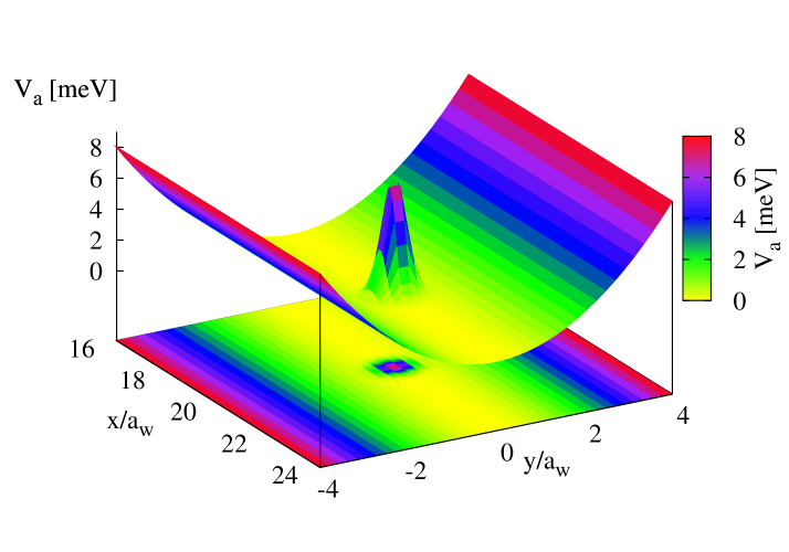
The considered embedded antidot is defined in the middle of the quantum wire as shown in Fig. 1, and can be described by a Gaussian-type potential
| (1) |
For performing numerical computation, the antidot related physical parameters are selected as follows: potential height of the antidot meV, the potential broadening parameter nm-2, and the longitudinal coordinate center with being the effective magnetic length of the wire to be defined later.
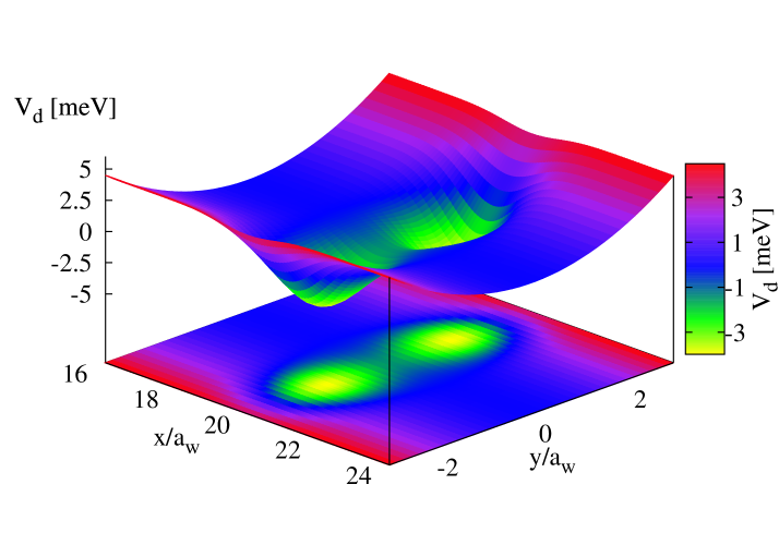
The parallel double-dot potential under consideration, shown in Fig. 2, is described by a number of Gaussian-type potentials
| (2) |
The strength of the coupling of the two parallel open quantum dots is tunable by the separation parameter and the strength of the magnetic field. In our numerical calculation, we shall select the strength of the double quantum dot meV, the broadening parameter nm-2, the longitudinal center , and the transverse off center parameter such that the two dots are separated by the distance of .
In the Landau gauge for the vector potential, the unperturbed Hamiltonian can be written as
| (3) |
where and are the charge and the effective mass of an electron, respectively. The confining potential is assumed to be parabolic. Using a mixed momentum-coordinate representationGurvitz95-Gudmundsson05 and making Fourier transform in time, the scattering wave function
| (4) |
can be separated into the coefficient functions and the shifted harmonic-oscillator-type eigenfunctions for the wire, namely where the shifting center = is momentum dependent. In the absence of magnetic field, this shifting center is identically zero. The effective magnetic length of the wire is related to the effective cyclotron frequency with being the two-dimensional cyclotron frequency. In the presence of a magnetic field, the quantized electron energy away from the scattering region is given byBerggren89-Tang-Vidar
| (5) |
where = are the transverse subband energy levels, and the second term denotes the kinetic energy with = and = .
To obtain the coefficient functions , one defines the momentum-coordinate space potential , which is a Fourier transform of the scattering potential . The overlap integral in the momentum space can thus be expressed as
| (6) | |||||
where is a dimensionless quantity. In the asymptotic region away from the scattering region, the unperturbed Green function can be expressed of the form , where the dimensionless wave vector = describes the dispersion relation in the asymptotic regions. After some algebra, one can obtain the Lippmann-Schwinger equation in the momentum space
| (7) | |||||
where is the coefficient function of the asymptotic regions. Therein, the envelope function of the incident wave packet is assumed to contain only positive values such that the wave packet is injected in the direction. For a given subband , the explicit form of the coefficient function can be expressed in terms of the -matrix
| (8) | |||||
where the -matrix is a solution of the integral equation
| (9) | |||||
Solving this integral equation for the -matrix, one can obtain the coefficient functions for the scattering region and construct the total wave function = containing an asymptotic part
| (10) | |||||
with = being the envelop function of the wave packet in momentum space, and a scattering part
| (11) | |||||
The transmission amplitude through the embedded quantum dot system for an electron with energy entering the scattering region from the channel in the left lead and leaving it via channel in the right lead that can be expressed in terms of the -matrix:
| (12) |
The conductance, according to the framework of multichannel Landauer-Büttiker formalism,Landauer-Buttiker is written as
| (13) |
where is the universal conductance quantum and is evaluated at Fermi energy. All the incident and scattered propagating modes have to be taken into account.
III Numerical Results
To investigate the magnetotransport properties of wave packet propagation in a nanostructure system embedded in a broad wire under a perpendicular magnetic field, we select the confinement parameter meV. In our numerical calculation, the magnetic field strengths are selected as and T with corresponding effective magnetic lengths and nm, respectively. We assume that the quantum wire is fabricated in a high-mobility GaAs-AlxGa1-xAs heterostructure such that the effective Rydberg energy meV and the Bohr radius nm. Below we shall explore the dynamic motion of the electron wave packet in a quantum wire under an applied perpendicular magnetic field with either an embedded antidot or an embedded double open quantum dot.
III.1 Embedded Antidot
Earlier work considering magnetotransport in an antidot was carried out by assuming that magnetic field is so strong that only the lowest Landau level is occupied.Sanchez04 The antidot can be formed by producing a potential hill with gates,Kirczenow94-Kataoka02 and behaves effectively like an artificial quantum impurity. It is thus warranted to devote further effort in developing numerical techniques in order to analyze the behavior of the electron wave packet propagation in a quantum wire with an embedded antidot in a tunable magnetic field.
Since the effective magnetic length is a function of magnetic field, we thus select the envelop parameters of the wave packet in the momentum space as and for T, and and for T, such that the wave packets are of similar shapes in momentum space as shown by the dotted blue curve in Fig. 3. The incident wave packet is selected to have contributions from the lowest subband for clarity. The initial electron envelop function at is a Gaussian wave packet in the momentum space with width such that the probability density of the wave packet in the momentum space is reduced by a factor of .
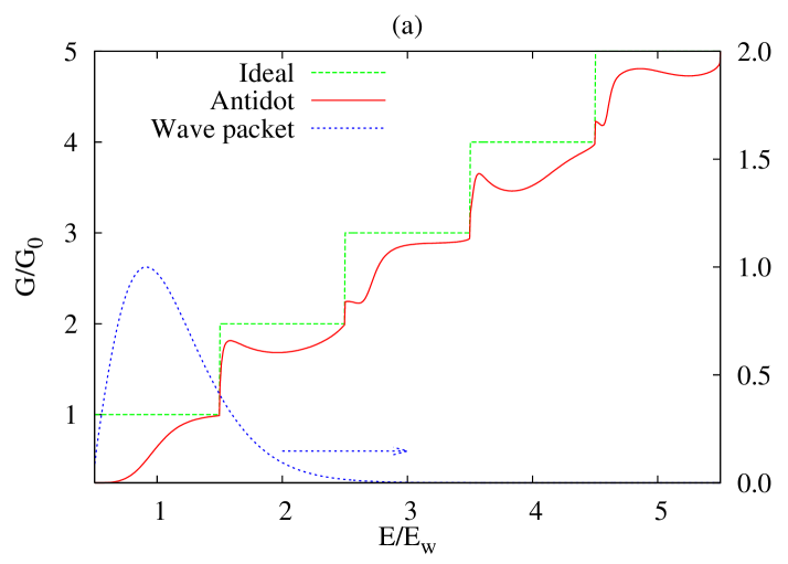
The energy dependence of the conductance for the traveling wave packet in an ideal wire and an antidot embedded wire are depicted in Fig. 3 by the dashed green and the solid red curves, respectively. The general feature in Fig. 3 is that the conductance is generally suppressed in the low kinetic energy regime but approaches the conductance of the ideal wire in the high kinetic energy regime. This is because the electron waves with lower kinetic energy are easier to be backscattered by the embedded antidot. For the case of T, the conductance manifests a smooth transition region in the lowest subband (). Low kinetic energy blocking phenomenon is significant at the third and the fifth conductance plateaus. However, in the second and the fourth plateaus, the Lorentz force pushes transversely the electron wave packet with mediate kinetic energy, and hence suppresses slightly the conductance plateaus.
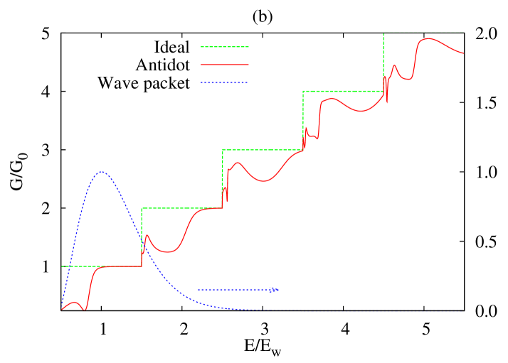
For the case of T, the conductance in the lowest subband region exhibits clear transition between the backward and the forward propagating energy regimes at around . A dip structure is clearly found at that corresponds to a short-lived quasibound state with negative binding energy. Such a dip structure becomes broader valley structure at higher subbands shifted slightly to the higher energy. This broadening indicates a shorter dwell time of the localized state at higher subbands. Sharp dip structures at , 3.52, and 4.54 demonstrate the formation of quasibound states with negative binding energy.Vidar05
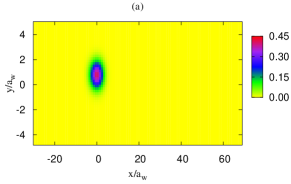
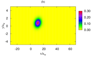
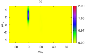
In Fig. 4, we show the time evolution of the wave packet traveling through the quantum wire with an embedded antidot for the case of T. Before the electron wave packet arrives at the scattering region, the wave packet center is shifted slightly in transverse direction to 0.8 due to the Lorentz force induced by the penetrating magnetic field as shown in Fig. 4(a) for ps. To estimate the longitudinal width of the incident Gaussian wave packet, it is convenient to define a Gaussian function in the real space with width such that varies from 0 to , and is reduced by a factor of . By this definition, one can estimate the width of the incident wave packet at being to obtain which is compatible with the Heisenberg uncertainty relation.
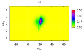
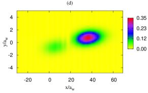
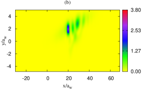
Figure 4(b) shows the time evolution of the wave packet at ps, it is found that the trajectory of the electron waves with higher kinetic energy is closer to the wire edge due to the magnetic field. Since the higher kinetic energy electron waves contain larger group velocity, the shape of the wave packet is skewed. The electron wave packet is then scattered by the antidot as shown in Fig. 4(c). The electron waves with higher kinetic energy can pass through the antidot but the lower kinetic energy part of the wave packet is reflected. Due to the Lorentz force, the backscattered wave packet is turned around to lower part of the quantum wire with wave packet center at [see Fig. 4(c)]. For longer evolution time ps, the scattered wave packets become broader and then leave the scattering region, as is shown in Fig. 4(d).
In Fig. 5, we show the time evolution of the wave packet traveling through the quantum wire with an embedded antidot for the case of T. Before the electron wave packet arrives at the scattering region, the wave packet has a shifting center at 1.8 due to the Lorentz force as shown in Fig. 5(a) for zero picoseconds. The wave packet is narrow in the direction, that is, . The electron wave packet is scattered by the antidot at ps, as is shown in Fig. 5(a). The part with higher kinetic energy can pass through the antidot but the part with lower kinetic energy is predominately reflected. Due to the magnetic field induced Lorentz force, the backscattered wave packet is turned around to lower part of the quantum wire with wave packet center at at ps (see Fig. 5(c)). For longer time ps, the scattered wave packets are getting broader—the reflected wave packet has distribution length and the transmitted wave packet has even broader distribution length , as is shown in Fig. 5(d). The spreading of a wave packet is a quantum diffusion phenomenon, which was utilized for possible application in a quantum kicked rotor system.Zhong01
In comparison to the incident wave packet in an applied magnetic field T, the incident wave packet in T has a wider longitudinal profile and a wave packet center closer to the middle of the quantum wire. It turns out that the group velocity of the wave packet for the case of T is greater than that of T. We would like to mention in passing that for a wave packet with momentum envelop function covering more subbands, the electron wave packet tends to form transversely skipping-like trajectories in both the forward and backward scattered wave packets due to the mode mixing interference between different subbands.
III.2 Embedded Parallel Double Dot
Electronic transport through coupled quantum nanostructures is of fundamental interest for the understanding of coherent resonant and superposition states. By coupling two quantum dots in seriesvdWiel03 or in parallel,Chen04 a double quantum dot is formed. Quantum transport through such a double-dot system has attracted considerable attention due to its versatility for various applications such as probing entanglement,Loss00-Schomerus07 detecting microwave manipulation of a single electron,Petta04 analyzing dephasing rate,Elhassan05 studying nonadiabatic transport under irradiation,Naber06 and readout of the coherent superposition of trajectories.Jordan06 The interdot coupling strength can be experimentally varied using gate electrodes.Chen04 ; Craig04
Earlier works considering electronic transport in double quantum dot systems were carried out using the Anderson-type hopping model by assuming that the system is isolated with weak coupling to the leads.Kiselev03-Hartmann04-Zarand06 Our previous work has devoted effort in developing numerical computation of magnetotransport in a transversely hill-separated parallel double open quantum dot system with strong coupling to the leads.Tang05 It is thus appropriate to analyze the propagation behavior of the electron wave packet in a quantum wire with an embedded parallel double open quantum dot to get better insight into the dynamical properties.
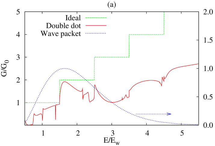
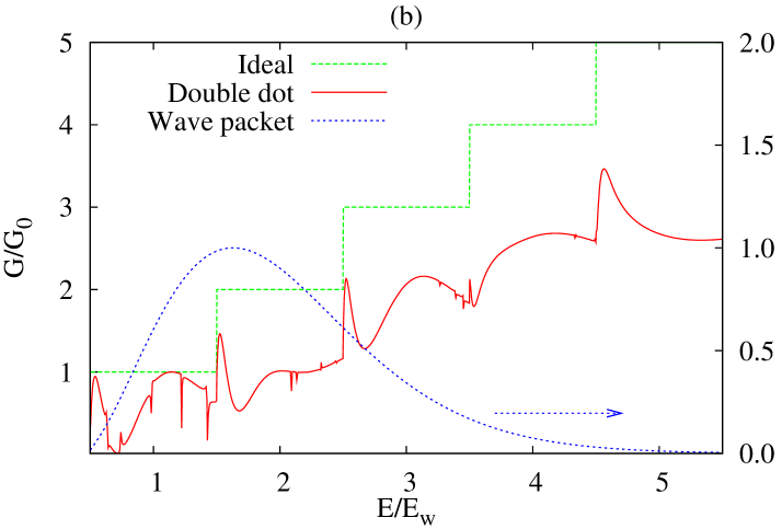
In Fig. 6, we show the energy dependence of the conductance in an ideal wire (dashed green), the conductance in a double-dot embedded quantum wire (solid red), and the envelop function of the wave packet in momentum space (dotted blue) for the cases of (a) , and (b) T. We select the envelop parameters of the wave packet in the momentum space as packet center and for T, and and for T, such that the wave packets are of similar shapes in momentum space.
For the case of T, shown in Fig. 6(a), we see that a perfect conductance gap formed at the kinetic energy regime () of the first subband. This fact indicates that the embedded double-dot system may be applicable as a quantum switch. The conductance gap is formed due to the cyclotron motion of electron wave between the two parallel dots. Fano line-shapes in conductance at energies and 2.37 manifest the quantum interference feature of the wave packet between the part forming quasibound states inside the double-dot system and the part with straight transmission. Furthermore, a sharp dip structure in conductance at energy indicates the forming of a quasibound state below the second subband threshold in the lead. The transport properties of electron waves in the second subband is very different to that in the first subband. The overall feature is that the low kinetic energy electron exhibits higher conductance. The strong suppression in conductance at higher subband implies the better inter-dot coupling enhancing backscattering.
Figure 6(b) shows the energy dependence of conductance for the case of T. The gap feature in conductance at the low kinetic energy of the first subband is narrower than that induced by the magnetic field T. The dip structure in conductance related to the formation of quasibound state at around the energy is almost the same as the case of T, but the dip structure at higher energy in the first subband is shifted toward the lower energy. A new clear sharp dip structure is formed just below the threshold of the second subband. Since the wave function of the electrons occupying the second subband in T fits the geometry of the double-dot system, the electron wave thus favors to turn around through the double-dot, and then the conductance is strongly suppressed. The conductance at energies higher than the third subband threshold for the case of T is a little higher than that of T.
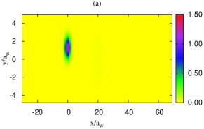
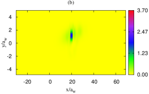
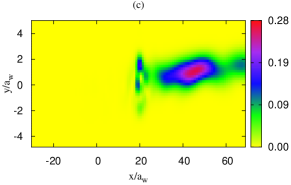
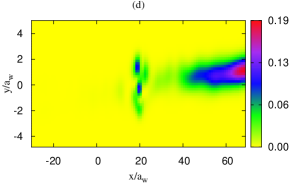
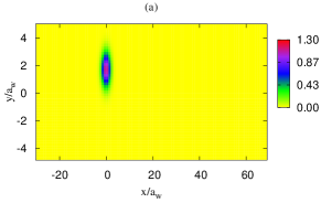
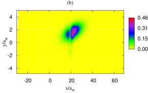
Figure 7 demonstrates the snapshots of the electron wave packet propagation through an embedded parallel double-dot system for the case of T at the time (a) 0; (b) 9; (c) 25; and (d) 38 ps. At time 0 ps, we see that the incident wave packet has a compact longitudinal distribution with height 1.5. In Fig. 7(b), at ps, the electron wave packet arrives at the upper open dot and form a clear quasibound state with packet height 2.0. At this moment, both the backward reflection and the forward transmission are blocked by the double-dot system.
During the time evolution ps, the higher energy part of the electron wave packet is closer to the upper boundary and traveling faster than the lower energy part of the wave packet. This makes the electron wave packet to skew with a clockwise rotation. Before being scattered by the double-dot system, the spreading effect proceeds slowly. When the electron wave packet is scattered by the double-dot system, the forward scattered wave packet exhibits faster spreading in the longitudinal direction manifesting a long-tail behavior caused by the slow release of the probability by the long-lived resonance state.
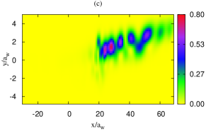
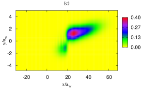
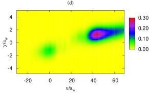
In Fig. 7(c), at the time 25 ps, part of the wave packet is clearly coupled to the lower dot although part of the wave packet has been forward scattered showing skipping-like trajectories and traveling into the right asymptotic region. The skipping-like behavior implies a significant intersubband mixing due to the broad wave packet distribution in the momentum space. At ps, the longitudinal distribution of the forward scattered wave packet is getting broader; and the localized part remains in the double-dot region with approximately a half packet height of the localized state formed at ps as shown in Fig. 7(b). We would like to mention in passing that the reflection wave packet takes more time to emerge than the transmission wave packet due to the formation of the quasibound states in the double-dot embedded system.
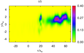
We show, in Fig. 8, that the snapshots of the electron wave packet propagation through an embedded parallel double-dot system for the case of T at the time (a) 0; (b) 11; (c) 21; (d) 40 ps. It is shown in Fig. 8(a) that, at time ps, the incident wave packet has a compact longitudinal distribution with probability density height 1.2. A clear localized quasibound state feature is found at 9 ps as is shown in Fig. 8(b). The height of the probability density of the localized state is twice the height of the initial wave packet. At this moment, the backward reflection is blocked and the forward transmission is relatively low.
The wave packet propagation at the moment ps is depicted in Fig. 8(c). The forward scattered wave packet exhibits rich and robust transport behavior. Not only the skipping-like wave packet flight is found, but also an interference feature attributed to the intersubband mixing is significantly manifested. At time ps shown in Fig. 8(d), the skipping-like trajectory is still significant but the interference feature is suppressed. In addition, the inter-dot coupling of the wave packet in T is weaker than that in T due to the stronger Lorentz force enhancing off-center shifting. The localized state for the case of T is covering two quantum dots whereas the localized state for the case of T is mainly in the upper dot. This implies that the T magnetic field fits better to the length scales of the double-dot system.
IV Concluding remarks
In this work we have developed a theoretical model by implementing the Lippmann-Schwinger formalism to demonstrate and elucidate the transport properties of a Gaussian-type electron wave packet traveling through a quantum wire with embedded quantum dots under a homogeneous perpendicular magnetic field. The magnetic field induces Lorentz force, which enriches the dynamics of electron wave packet propagation. We have found that quantum skipping-like oscillation trajectory of a wave packet is induced in an appropriate magnetic field when the wave packet envelop function covers the lowest two subbands. This is a quantum forerunner to the well known skipping orbit motion of classical particles.
For the case of an embedded antidot, the electron wave packet has been considered with momentum envelop covering the lowest two subbands. The wave packet propagation exhibiting non-skipping-like trajectories implies that the significance of the wave packet propagation is staying in the lowest subband. The part of the wave packet with high kinetic tends to go through the antidot system but the the part with low kinetic energy is backscattered by the scattering region. Quasibound state features with negative binding energies have also been seen to play an active role in the scattering process.
For the case of embedded double quantum dot, we have found a robust trapping effect of the electronic wave packet moving into the double-dot system and forming localized states. If there are several bound states, the electrons make multiple scattering in the coupled double quantum dot resulting in a superposition of these bound states, exhibiting oscillating behavior in the double-dot system. The parallel double-dot system enables the electron wave packet performing resonant coupling between two dots in an appropriate magnetic field and then allows electron wave packet performing inter-edge backscattering.
The coherent motion of electron waves through open nanostructures in a penetrating magnetic field may offer promising approaches to semiconductor spintronicsZozoulenko04 and controlling the dynamics of coherent quantum states for quantum information processing.Harris01 To explore these new directions, we need to track the motion of electron waves in an applied magnetic field. The cooled scanning probe microscope renders the possibility of imaging the electron wave trajectories by using the scanning tip as a movable gate.Topinka00 Very recently, quantum dot embedded mesoscopic system has been utilized for the coherent probing of excited quantum dot states.Sigrist07 We hope that our paper will stimulate experimental interest to nanostructure embedded quantum systems in the strong coupling regime, which may provide a useful tool for the dynamical quantum manipulation of charged carriers.
Acknowledgements.
The authors acknowledge financial support from the Research and Instruments Funds of the Icelandic State, the Research Fund of the University of Iceland, the Icelandic Science and Technology Research Programme for Postgenomic Biomedicine, Nanoscience and Nanotechnology, and the National Science Council of Taiwan. C.S.T. is grateful to the computational facilities supported by the National Center for High-Performance Computing in Taiwan and the University of Iceland.References
- (1)
- (2) See, for example, M. Law, J. Goldberger, and P. Yang, Annu. Rev. Mater. Res. 34, 83 (2004); J. Noborisaka, J. Motohisa, S. Hara, and T. Fukui, Appl. Phys. Lett. 87, 093109 (2005).
- (3) B. J. van Wees, H. van Houten, C. W. J. Beenakker, J. G. Williamson, L. P. Kouwenhoven, D. van der Marel, and C. T. Foxon, Phys. Rev. Lett. 60, 848 (1988); S. J. Koester, C. R. Bolognesi, M. J. Rooks, E. L. Hu, and H. Kroemer, Appl. Phys. Lett. 62, 1373 (1993); G. Scappucci, L. Di Gaspare, E. Giovine, A. Notargiacomo, R. Leoni, and F. Evangelisti, Phys. Rev. B 74, 035321 (2006).
- (4) C. S. Chu and R. S. Sorbello, Phys. Rev. B 40, 5941 (1989); P. F. Bagwell, ibid. 41, 10354 (1990); J. H. Bardarson, I. Magnusdottir, G. Gudmundsdottir, C. S. Tang, A. Manolescu, and V. Gudmundsson, ibid. 70, 245308 (2004).
- (5) J. F. Weisz and K.-F. Berggren, Phys. Rev. B 40, 1325 (1989); C. S. Tang and V. Gudmundsson, ibid. 74, 195323 (2006); V. Gudmundsson and C. S. Tang, ibid. 74, 125302 (2006).
- (6) O. Olendski, L. Mikhailovska, Phys. Rev. B 72, 235314 (2005).
- (7) M. C. Rogge, F. Cavaliere, M. Sassetti, R. J. Haug, and B. Kramer, New J. Phys. 8, 298 (2006).
- (8) J. J. Koonen, H. Buhmann, and L. W. Molenkamp, Phys. Rev. Lett. 84, 2473 (2000).
- (9) A. Löfgren, C. A. Marlow, T. E. Humphrey, I. Shorubalko, R. P. Taylor, P. Omling, R. Newbury, P. E. Lindelof, and H. Linke, Phys. Rev. B 73 235321 (2006).
- (10) K. E. Aidala, R. E. Parrott, T. Kramer, E. J. Heller, R. M. Westervelt, M. P. Hanson, and A. C. Gossard, Nature Phys. 3, 464 (2007).
- (11) J. Gabelli, G. Fève, J.-M. Berroir, B. Placais, A. Cavanna, B. Etienne, Y. Jin, D. C. Glattli, Science 313, 499 (2006); J. Gabelli, G. Fève, T. Kontos, J.-M. Berroir, B. Placais, D. C. Glattli, B. Etienne, Y. Jin, and M. Büttiker, Phys. Rev. Lett. 98, 166806 (2007).
- (12) C. S. Tang and C. S. Chu, Phys. Rev. B 53, 4838 (1996); ibid. Physica B 254, 178 (1998); ibid. Phys. Rev. B 60, 1830 (1999); ibid. Physica B 292, 127 (2000); C. S. Tang, Y. H. Tan, and C. S. Chu, Phys. Rev. B 67, 205324 (2003); B. H. Wu and J. C. Cao, Phys. Rev. B 73, 245412 (2006).
- (13) C. S. Tang and C. S. Chu, Solid State Commun. 120, 353 (2001); S. W. Chung, C. S. Tang, C. S. Chu, and C. Y. Chang, Phys. Rev. B 70, 085315 (2004); J. Bylander, T. Duty, and P. Delsing, Nature 434, 361 (2005).
- (14) M. D. Blumenthal, B. Kaestner, L. Li, S. Giblin, T. J. B. M. Janssen, M. Pepper, D. Anderson, G. Jones, and D. A. Ritchie, Nature Phys. 3, 343 (2007).
- (15) A. G. Mal’shukov, C. S. Tang, C. S. Chu, and K. A. Chao, Phys. Rev. Lett. 95, 107203 (2005); C. C. Kaun and T. Seideman, ibid. 94, 226801 (2005); F. Pistolesi and R. Fazio, New J. Phys. 8, 113 (2006).
- (16) B. Szafran and F. M. Peeters, Phys. Rev. B 72, 165301 (2005).
- (17) T. Okunishi, Y. Ohtsuka, M. Muraguchi, and K. Takeda, Phys. Rev. B 75, 245314 (2007); W. H. Kuan, C. S. Tang, and C. H. Chang, ibid. 75, 155326 (2007); P. G. Luan and C. S. Tang, J. Phys.: Condens. Matter 19, 176224 (2007).
- (18) S. A. Gurvitz, Phys. Rev. B 51, 7123 (1995); V. Gudmundsson, Y. Y. Lin, C. S. Tang, V. Moldoveanu, J. H. Bardarson, and A. Manolescu, Phys. Rev. B 71, 235302 (2005).
- (19) See, e.g., M. Di Ventra and N. D. Lang, Phys. Rev. B 65, 045402 (2001).
- (20) M. Büttiker, Y. Imry, R. Landauer, and S. Pinhas, Phys. Rev. B 31, 6207 (1985); Y. Imry and R. Landauer, Rev. Mod. Phys. 71, S306 (1999).
- (21) D. Sanchez and M. Büttiker, Phys. Rev. Lett. 93, 126802 (2004).
- (22) G. Kirczenow, A. S. Sachrajda, Y. Feng, R. P. Taylor, L. Henning, J. Wang, P. Zawadzki, and P. T. Coleridge, Phys. Rev. Lett. 72, 2069 (1994); M. Kataoka, C. J. B. Ford, M. Y. Simmons, and D. A. Ritchie, ibid. 89, 226803 (2002).
- (23) V. Gudmundsson, C. S. Tang, and A. Manolescu, Phys. Rev. B 72, 153306 (2005).
- (24) J. Zhong, R. B. Diener, D. A. Steck, W. H. Oskay, M. G. Raizen, E. W. Plummer, Z. Zhang, and Q. Niu, Phys. Rev. Lett. 86, 2485 (2001).
- (25) For a general overview see, e.g., W. G. van der Wiel, S. D. Franceschi, J. M. Elzerman, T. Fujisawa, S. Tarucha, L. P. Kouwenhoven, Rev. Mod. Phys. 75, 1 (2003).
- (26) J. C. Chen, A. M. Chang, and M. R. Melloch, Phys. Rev. Lett. 92, 176801 (2004).
- (27) D. Loss and E. V. Sukhorukov, Phys. Rev. Lett. 84, 1035 (2000); H. Schomerus and J. P. Robinson, New J. Phys. 9, 67 (2007).
- (28) J. R. Petta, A. C. Johnson, C. M. Marcus, M. P. Hanson, and A. C. Gossard, Phys. Rev. Lett. 93, 186802 (2004).
- (29) M. Elhassan, J. P. Bird, R Akis, D. K. Ferry, T. Ida, and K. Ishibashi, J. Phys.: Condens. Matter 17, L351 (2005).
- (30) W. J. M. Naber, T. Fujisawa, H. W. Liu, and W. G. van der Wiel, Phys. Rev. Lett. 96, 136807 (2006).
- (31) A. N. Jordan, A. N. Korotkov, and M. Büttiker, Phys. Rev. Lett. 97, 026805 (2006).
- (32) N. J. Craig, J. M. Taylor, E. A. Lester, C. M. Marcus, M. P. Hanson, and A. C. Gossard, Science 304, 565 (2004).
- (33) M. N. Kiselev, K. Kikoin, and L. W. Molenkamp, Phys. Rev. B 68, 155323 (2003); U. Hartmann and F. K. Wilhelm, ibid. 69, 161309(R) (2004); G. Zaránd, C.-H. Chung, P. Simon, and M. Vojta, Phys. Rev. Lett. 97, 166802 (2006).
- (34) C. S. Tang, W. W. Yu, and V. Gudmundsson, Phys. Rev. B 72, 195331 (2005).
- (35) I. V. Zozoulenko and M. Evaldsson, Appl. Phys. Lett. 85, 3136 (2004).
- (36) J. Harris, R. Akis, and D. K. Ferry, Appl. Phys. Lett. 79 2214 (2001).
- (37) M. A. Topinka, B. J. LeRoy, S. E. J. Shaw, E. J. Heller, R. M. Westervelt, K. D. Maranowski, A. C. Gossard, Science 289, 2323 (2000); M. A. Topinka, R. M. Westervelt, and E. J. Heller, Phys. Today 56, 47 (2003).
- (38) M. Sigrist, T. Ihn, K. Ensslin, M. Reinwald, and W. Wegscheider, Phys. Rev. Lett. 98, 036805 (2007).